Remote H and L terminals
There are two terminals marked REMOTE_H and REMOTE_L.
The default function of these terminals is to switch the Multi RS on or off remotely.
Note
From the factory, these two terminals are connected together with a wire link. This enables the Multi RS to turn on when its main physical switch is on.
To use the terminals for remote connections, the wire link should be removed.
These two contacts can be configured for either remote on/off (default), or for 2-wire BMS mode.
When multiple units are combined in a system — for example in a three-phase setup — you can connect the contact wires to any single unit. The contact’s state is then shared with the rest of the system through the VE.Can connections.
You only need to configure the unit which has the contact wires connected to it.
Remote on/off functionality:
The factory fitted wire link can be removed and then wires can be connected to an external switch contact. The switch contact can then be used to switch the Multi RS on or off.
This is the default configuration in VictronConnect, no configuration changes are necessary on a new unit. The configuration can be checked in Remote mode in the Battery settings menu.
The Multi RS will be switched on if the inputs are wired in one of the four ways pictured on the right.
| 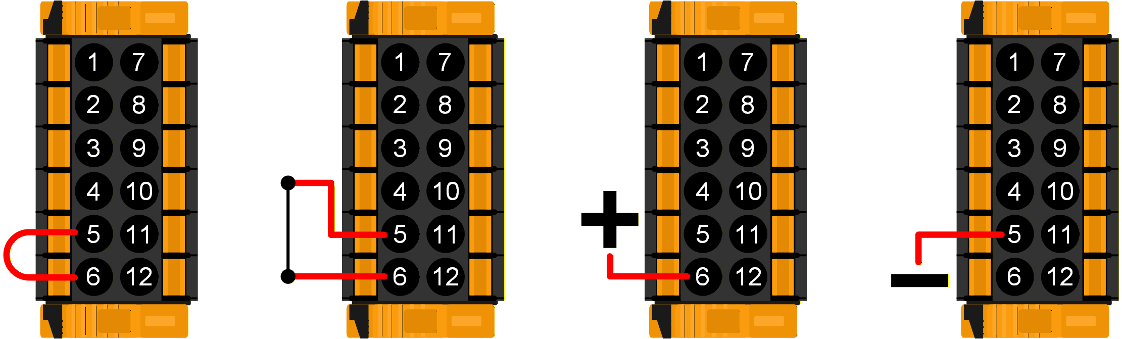 |
The Multi RS will be switched off if the inputs are wired in one of the four ways pictured on the right.
| 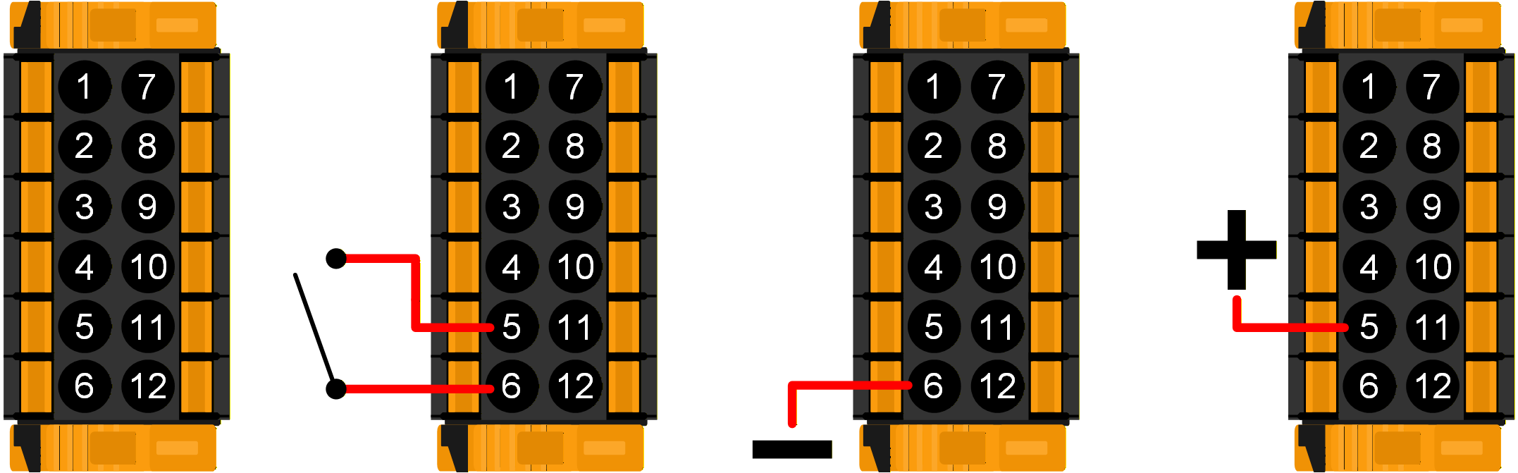 |
2-wire BMS mode:
The REMOTE_H and REMOTE_L terminals can also be configured for interfacing with a 2-wire BMS. Two separate contacts on the BMS control whether the Multi RS is allowed to charge or discharge. This is configured in VictronConnect, see Remote mode in the Battery settings menu.
Change the mode from "Remote on/off" to "2-wire BMS".
The diagrams below demonstrate what mode the Multi RS will be in depending upon the state of the REMOTE_H and REMOTE_L terminals.
Note
In 2-wire BMS mode, if the REMOTE_H and REMOTE_L terminals are linked (and not connected to +48V), the Multi RS will be on, but charging will be disabled.
The BMS' "Allow to charge" and "Allow to discharge" contacts are both closed. The REMOTE_H and REMOTE_L terminals are both pulled up to +48V through the BMS switch contacts. The Multi RS operates normally, and is allowed to charge and discharge the battery. | 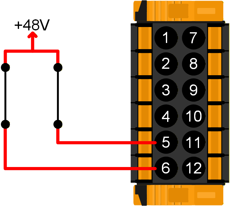 |
The BMS has opened its "Allow to charge" contact. The REMOTE_H is pulled up to +48V through the BMS contact and REMOTE_L terminal is open circuit (floating). The Multi RS stops charging the battery from AC and/or solar sources, but continues to discharge the battery as normal. | 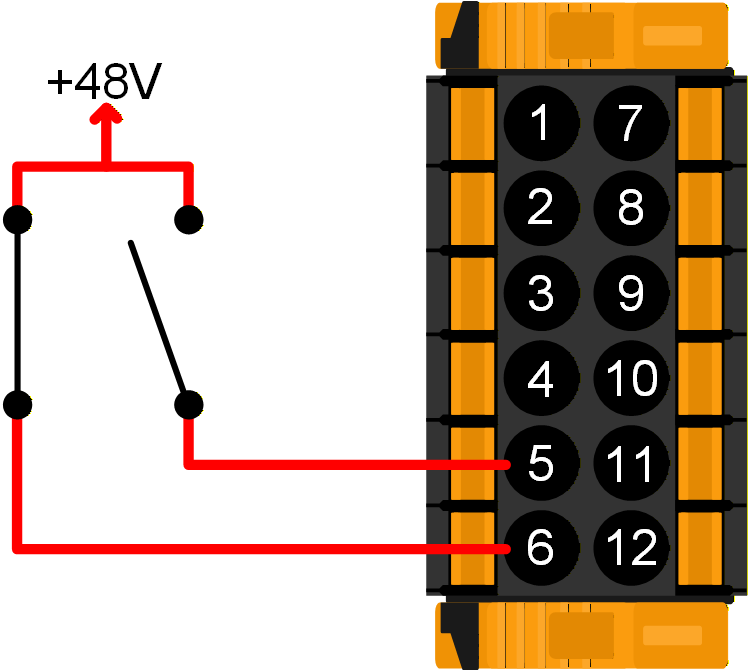 |
The BMS has opened its "Allow to discharge" contact. The REMOTE_L is pulled up to +48V through the BMS contact and REMOTE_H terminal is open circuit (floating). The Multi RS stops discharging the battery, but continues to charge the battery from AC and/or solar sources if available. | 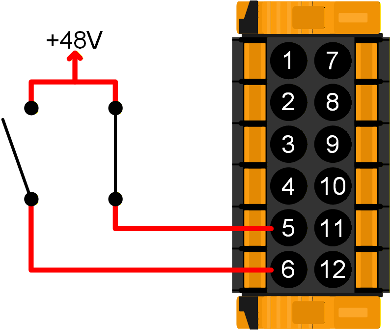 |
The BMS' "Allow to charge" and "Allow to discharge" contacts are both open. The REMOTE_H and REMOTE_L terminals are both open circuit (floating). Neither charging nor discharging is allowed, so the Multi RS switches off. | 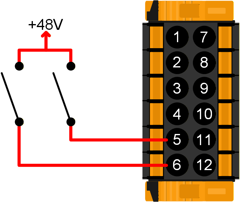 |