7. Troubleshooting guide
For unexpected behaviour or suspected product faults, refer to this chapter.
Start by checking the common issues described here. If the problem persists, contact the point of purchase (Victron dealer or distributor) for technical support.
If you're unsure who to contact or if the point of purchase is unknown, refer to the Victron Energy Support webpage.
7.1. Batteries are not being charged
There are a few situations that could cause the batteries to not charge.
This could be indicated by low or no battery current shown in the VictronConnect app.
The battery is full, and no more current is needed.
Wrong configuration (voltage or current set too low).
The charger is externally controlled (ESS or DVCC).
The battery temperature is too high and temperature-compensated charging is active or set incorrectly,
Reverse PV polarity.
7.1.1. Battery is full
Once the battery is full the Multi RS will stop charging or will greatly reduce the charge current.
This is especially the case when at the same time the DC loads in the system are not consuming any power from the battery.
To find out what the state of charge (SoC) of the battery is, check the battery monitor (if present), or alternatively, check what charge stage the controller is in. Also, observe that the solar cycle is (briefly) progressing through these charge stages at the beginning of the daily charge cycle:
Bulk stage: 0-80% SoC.
Absorption stage 80-100% SoC.
Float or storage stage: 100% SoC.
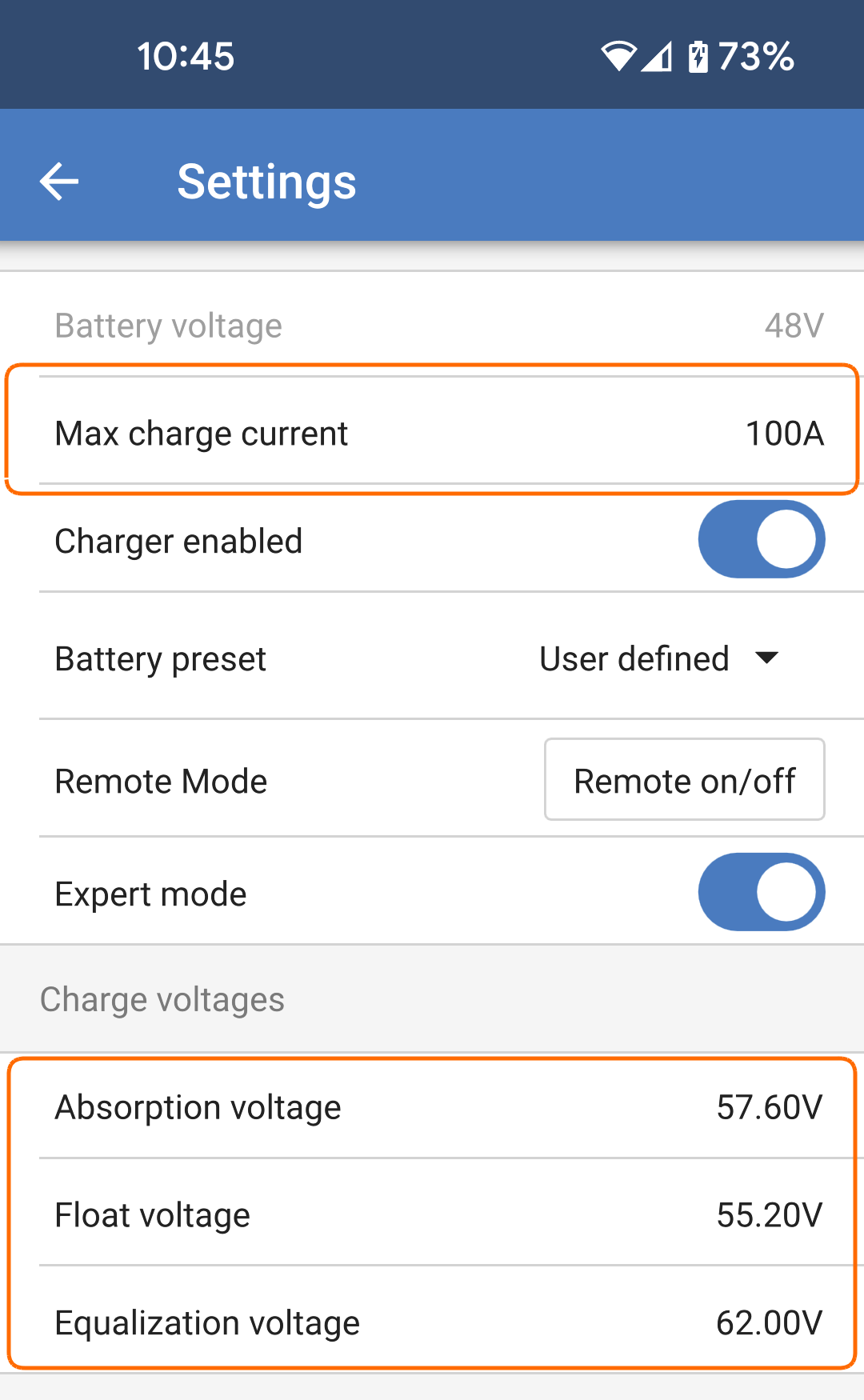
Be aware that it can also be possible that the Multi RS thinks the battery is full, while in reality, the battery is not full. This can occur when the charge voltages have been set too low, causing the Multi RS to prematurely switch to the absorption or float stage. For more information see the Battery settings too low chapter.
7.1.2. Battery settings too low
|
|
7.2. Batteries are undercharged
This chapter deals with possible reasons why the Multi RS is not sufficiently charging the batteries and the steps you can take to check or remedy the situation.
The batteries take too long to charge.
The batteries are not fully charged at the end of the day.
The charge current from the Multi RS is less than expected.
7.2.1. Too much DC load
The Multi RS does not only charge the batteries, it also provides power for the system’s loads.
The battery will only be charged when the power available from the PV panels exceeds the power being drawn by the loads in the system, like lights, fridge, inverter, and so on.
If the system battery monitor is correctly installed and configured you can see how much current is going in (or out) of the battery and the Multi RS will tell you how much current the solar array is generating.
A positive sign alongside the current reading means that current is flowing in to the battery, while a negative sign means that current is being drawn from the battery.
7.2.2. Battery cable voltage drop
If there is a voltage drop over the battery cables, the solar charger will output the correct voltage, but the batteries will receive a lower voltage which can potentially lead to undercharged batteries. A voltage drop in excess of 2.5% is unacceptable.
Battery charging will take longer.
The battery receives a too-low charge voltage.
There is a loss of charge power.
The battery cables heat up.
Battery cables with insufficient cross-sectional area.
Badly crimped cable lugs or terminals.
Loose terminal connections.
Bad or loose fuse(s).
For more information on cabling issues and voltage drop see the Wiring unlimited book.
This check must be performed while the Multi RS is charging with a full current. Typically best done in the morning. Use the VictronConnect app to check the output current.
Measure the voltage on the battery terminals of the Multi RS using the VictronConnect app or a multimeter.
Measure the battery voltage on the terminals of the battery using a multimeter.
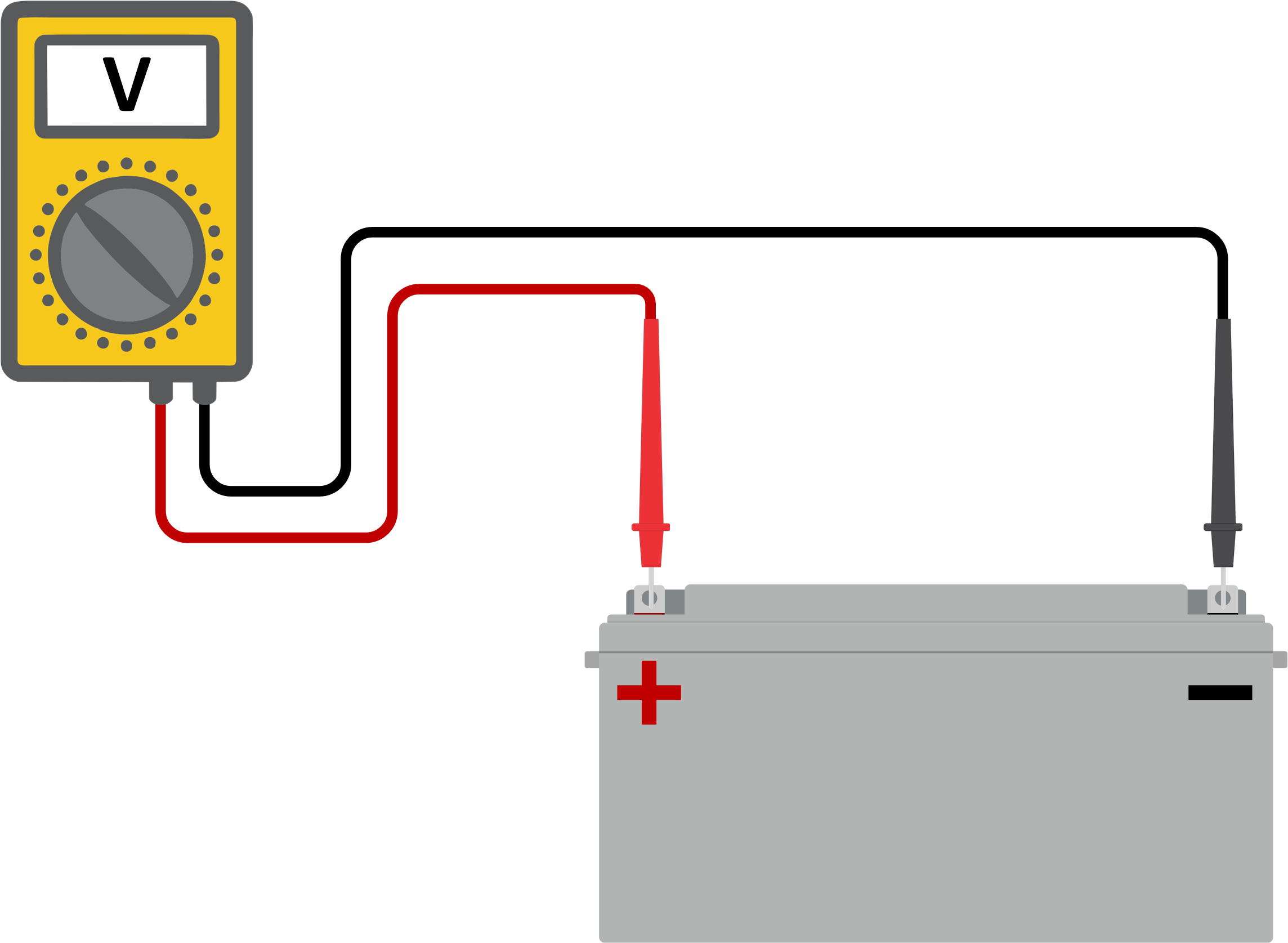
Compare the two voltages to see if there is a voltage difference.
7.2.3. Wrong temperature compensation setting
If the temperature compensation coefficient is set incorrectly, the batteries can be undercharged or be overcharged. The temperature compensation can be set via VictronConnect or via a display.
To find out the correct temperature compensation coefficient setting for your battery, refer to the battery documentation. When in doubt use the default value of -64.80mV/°C for lead acid batteries and disable the temperature compensation setting for lithium batteries.
7.3. Batteries are overcharged
Warning
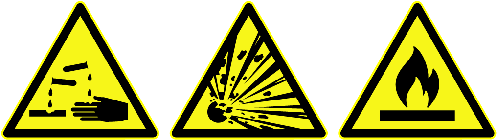
Batteries that are being overcharged are very dangerous! There is a risk of battery explosion, fire or acid leakage. Do not smoke, create sparks or have open flames in the same room as where the batteries are located.
 |
Incorrect charge voltage settings.
Applying equalization while the battery is not suitable for equalization.
High current and undersized batteries.
Battery faults.
Too high current, while the battery is not accepting charge anymore because of aging or prior mistreatment.
7.3.1. Battery charge voltages too high
If the battery charge voltages are set too high this will cause the batteries to overcharge.
Check if all the battery charge voltages (absorption and float) are set correctly.
The charge voltages have to match the recommended voltages as stated in the battery manufacturers documentation.
7.3.2. Battery unable to deal with equalization
During equalization, the battery charge voltage will be quite high and if the battery is unsuitable to be equalized, the battery will be overcharged.
Not all batteries can be charged with equalization voltages. Check with the battery manufacturer if the battery you are using needs a periodic equalizing charge.
Generally speaking, sealed batteries as well as lithium batteries don’t need equalizing and therefore should not be.
7.3.3. Battery old or faulty
A battery that is at the end of its service life or has been damaged by incorrect use, can be prone to being overcharged.
A battery contains a number of cells that are connected in series. When a battery is old or has been damaged, a likely scenario is that one of these cells is not operational anymore.
When the faulty battery is charged, the damaged cell will not accept charge and the remaining cells will receive the broken cell’s charge voltage and thus will be overcharged.
To fix this, replace the battery. In case of multiple battery system replace the whole battery bank. It is not recommended to mix batteries of different ages in one battery bank.
It is hard to tell what has exactly happened to a battery during its lifetime. The solar charger will keep 30 day of battery voltage history. If the system also contains a battery monitor, or if the system is connected to VRM, the battery voltages and the cycle history of the battery can be accessed This will give a complete picture of the battery history and it can be determined if the battery is near the end of its service life or has been abused.
Find out how many charge and discharge cycles the battery has been subjected to. Battery lifetime correlates to the number of cycles.
Check how deep the battery has been discharge on average. A battery will last for less cycles if deeply discharged, compared to more cycles if discharged less deep.
Refer to the battery data sheet to find out how many cycles at what average discharge the battery is capable of. Compare this with the battery history and determine if the battery is near the end of its service live.
Check if the battery has been totally discharged at all. Total and very deep discharge will damage a battery. Check the battery monitor setting history on the VRM portal. Look for the deepest discharge, the lowest battery voltage and the number of full discharges.
Check if the battery has been charged with a too high voltage. Very high charge voltage will damage the battery. Check the maximum battery voltage and the high voltage alarms in the battery monitor. Check if the measured maximum voltage has exceeded the battery manufacturer recommendations.
7.4. Communication problems
This chapter describes issues that might arise when the Multi RS is connected to the VictronConnect app, other Victron devices or third-party devices.
7.4.1. Bluetooth
Please note that it is highly unlikely that the Bluetooth interface is faulty. The problem is most likely caused by something else. Use this chapter to quickly rule out some of the common causes of Bluetooth issues.
For a full troubleshooting guide see the VictronConnect manual.
Check if Bluetooth is enabled
It is possible to enable/disable Bluetooth in the product settings. To re-enable:
Connect to the Multi RS via the VE.Direct port.
Navigate to the controller settings and then to "product info".
Re-enable Bluetooth.
Check if the Multi RS is powered-up
Bluetooth is active as soon as the Multi RS is powered-up.
Check that Bluetooth is in range
In open space the maximum Bluetooth distance is about 20 meters. In a build-up area, inside a house, a shed, a vehicle or a boat this distance can be a lot less.
The Windows VictronConnect app does not support Bluetooth
The Windows version of the VictronConnect app does not support Bluetooth. Use an Android, iOS or macOS device instead. Alternatively, connect using a VE.Direct to USB interface.
The controller is missing in the VictronConnect app device list
Some steps to try to resolve this issue are:
Press the orange refresh button at the bottom of the VictronConnect app device list and check if the Multi RS is now listed. Only one phone or tablet can be connected to the Multi RS at any given time. Make sure no other devices are connected and try again.
Try to connect to another Victron product, does this work? If that also does not work, there probably is an issue with the phone or tablet.
Rule out any issues with the phone or the VictronConnect app by using another phone or tablet and try again.
If still unresolved, refer to the VictronConnect app manual.
PIN code lost
If you have lost the PIN code, you will need to reset the PIN code to its default PIN code. This is done in the VictronConnect app:
Navigate to the device list of the VictronConnect app.
Enter the Multi RS's unique PUK code as printed on its product information sticker.
Click on the option symbol next to the solar charger listing.
A new window will open which allows you to reset the PIN code back to its default: 000000.
How to communicate without Bluetooth
In case Bluetooth is not functional, turned off or unavailable, the VictronConnect app can still communicate via the Multi RS’s VE.Direct port. Or, if the Multi RS is connected to a GX device, the VictronConnect app can communicate via VRM. For more information see the VictronConnect app chapter.
7.4.2. VE.Direct port
These are not common and if this occurs it is probably due to one of these issues listed in this paragraph.
Physical cable connector or data port issues Try a different VE.Direct cable and see if the Multi RS will now communicate. Is the connector inserted properly and deep enough? Is the connector damaged? Inspect the VE.Direct port, are there bent pins? If this is the case, use long nose pliers to straighten the pins, while the unit is unpowered.
Note, unlike most other Victron products it is not possible to connect the Multi RS to a GX device (i.e. Cerbo GX) using the VE.Direct interface. You must use the VE.Can interface to connect to a GX device.
7.5. Error code overview
Error 2 - Battery voltage too high:
This error will auto-reset after the battery voltage has dropped. This error can be due to other charging equipment connected to the battery or a fault in the charge controller.
Error 3, Error 4 - Remote temperature sensor failure:
Check if the T-sense connector is properly connected to a remote temperature sensor. Most likely cause: the remote T-sense connector is connected to the BAT+ or BAT- terminal. This error will auto-reset after proper connection.
Error 5 - Remote temperature sensor failure (connection lost):
Check if the T-sense connector is properly connected to a remote temperature sensor. This error will not auto-reset.
Error 6, Error 7 - Remote battery voltage sense failure:
Check if the V-sense connector is properly connected to the battery terminals. Most likely cause: the remote V-sense connector is connected in reverse polarity to the BAT+ or BAT- terminals.
Error 8 - Remote battery voltage sense failure (connection lost):
Check if the V-sense connector is properly connected to the battery terminals.
Error 11 - Battery high ripple voltage:
High DC ripple is usually caused by loose DC cable connections and/or too thin DC wiring. After the inverter has switched off due to high DC ripple voltage, it waits 30 seconds and then restarts.
After three restarts followed by a shutdown due to high DC ripple within 30 seconds of restarting, the inverter will shutdown and stops retrying. To restart the inverter, switch it Off and then On.
Continuous high DC ripple reduces the inverter life expectancy.
Error 17 - Controller overheated despite reduced output current:
This error will auto-reset after Multi RS has cooled down. Check the ambient temperature and check for obstructions near the ventilation grilles,
Error 20 - Maximum Bulk-time exceeded:
The maximum bulk time protection feature was later removed removed.
If you do see this error, then update to the latest firmware.
If you then still have the error, perform a reset to factory defaults of the configuration, and reconfigure the Multi RS.
Error 22, Error 23 - Internal temperature sensor failure:
The internal temperature measurements are out of range.
Disconnect all wires, and then reconnect all wires, to restart the Multi RS.
This error will not auto-reset.
If the error remains, please contact your dealer, there might be a hardware defect.
Error 27 - Charger short circuit:
This condition indicates an over-current condition on the battery side. It can occur when a battery is attached to the Multi RS using a contactor. Or in case the Multi RS starts up without a battery connected but connected to an inverter that has a large input capacitance.
This error will auto-reset. If the error does not auto-reset disconnect the Multi RS from all power-sources, wait 3 minutes, and power up again. If the error persists the Multi RS is probably faulty.
Error 29 - Overcharge protection:
This error will auto-reset once the battery voltage drops below the float voltage. To protect the battery from over-charging the battery is disconnected.
Possible causes:
Over-sized PV array configuration, if there are too many panels in series the battery voltage cannot be reduced any further. Consider wiring more PV panels in parallel to reduce the voltage.
Configuration issue, check if the battery settings match with the installation (especially absorption and float voltage settings).
Another charger in the system raises the battery voltage above the expected level.
This error will auto-reset after PV-voltage has dropped to safe limit. This error is an indication that the PV-array configuration with regard to open-circuit voltage is critical for the Multi RS. Check configuration, and if required, re-organise panels.
The current from the solar-panel array has exceeded the rated current limit. This error could be generated due to an internal system fault. Disconnect the Multi RS from all power-sources, wait 3 minutes, and power-up again. If the error persists the Multi RS is probably faulty, contact your dealer.
Please upgrade your firmware to at least v1.08 as the issues causing this error have been addressed.
If you are using firmware v1.08 or newer this error indicates that the internal dc voltage is too high. This error will auto-reset. If the error does not auto-reset disconnect the Multi RS from all power-sources, wait 3 minutes, and power up again. If the error persists the Multi RS is probably faulty.
PV panel isolation resistance too low. Check the PV array cabling and panel isolation, the Multi RS restarts automatically once the issue is resolved.
The ground leakage current in the PV array exceeds the allowed 30mA limit. Check the PV array cabling and panel isolation. Check the installation and restart the Multi RS using the power-switch.
Error 43 - Inverter shutdown (ground fault):
The voltage difference between Neutral and Ground is too high.
Multi RS (not connected to the grid):
The internal ground relay is activated but the voltage over the relay is too high. The relay might be damaged.
Multi RS (connected to the grid):
The ground wire in the installation is not present or not connected properly.
Line and Neutral are swapped in the installation.
This error will not auto-reset. Check the installation and restart the Multi RS using the power-switch.
Error 50, Error 52 - Inverter overload, inverter peak current:
Some loads like motors or pumps draw large inrush currents in a start-up situation. In such circumstances, it is possible that the start-up current exceeds the over current trip level of the Multi RS. In this case the output voltage will quickly decrease to limit the output current of the inverter. If the over current trip level is continuously exceeded, the Multi RS will shut down: wait 30 seconds and then restart Multi RS.
The Multi RS can supply more power than the nominal power level for a short time. If the time is exceed the Multi RS stops.
After three restarts followed by another overload within 30 seconds of restarting, the Multi RS will shutdown and remain off. To restart the Multi RS, switch it Off, then On.
If the error persists reduce the load on the AC out terminal by switching off or disconnecting appliances.
Error 51 -Inverter temperature too high:
A high ambient temperature or enduring high load may result in shut down to over temperature. Reduce load and/or move the Multi RS to better ventilated area and check for obstructions near the fan outlets.
The Multi RS will restart after 30 seconds. The inverter will not stay off after multiple retries.
Error 53 - Inverter output voltage:
If the battery voltage is getting low and a large load is applied to the AC output the Multi RS is unable to maintain the proper output voltage. Recharge the battery or reduce the AC loads to continue operation.
Error 54 - Inverter output voltage:
If the battery voltage is getting low and a large load is applied to the AC output the Multi RS is unable to maintain the proper output voltage. Recharge the battery or reduce the AC loads to continue operation.
If the error immediately pops up when switching on the Multi RS (without load) on a full battery the cause is most likely a broken replaceable internal fuse. Contact your Victron dealer for support.
Error 55, Error 56, Error 58 - Inverter self test failed:
The Multi RS performs diagnostic tests before it activates its output. In the case that one of these tests fails an error message is displayed and the Multi RS does not turn on.
First try to restart the Multi RS, by switching it Off, and then On. If error persists the Multi RS is probably faulty.
Error 57 - Inverter AC voltage on output:
There is already AC voltage on the AC out terminal before switching on the Multi RS. Check that the AC out is not connected to a mains outlet or to another Multi RS.
This error will not auto-reset. Check the installation and restart the Multi RS using the power-switch.
Error 59 - AC-IN1 relay test fault:
Automatic checking of the disconnect means failure. This usually indicates a broken relay (sticky contact) in the AC input stage.
Error 65 - Communication warning:
Communication with one of the paralleled Multi RS's was lost. To clear the warning, switch the Multi RS off and back on again.
Error 66 - Incompatible device:
The Multi RS is being paralleled to another Multi RS that has different settings and/or a different charge algorithm.
Make sure all settings are the same and update firmware on all Multi RS's to the latest version.
This error also appears if Multi RS's are connected to a GX device while configured for a VE.Smart network. Disable the VE.Smart networking features and use DVCC on the GX instead.
Further troubleshooting steps described here.
Error 67 - BMS Connection lost:
This error shows when the Multi RS is configured to be controlled by a BMS, but does not receive any BMS control messages. In that situation, the Multi RS stops charging by reducing its output voltage to the battery base voltage. This is a safety mechanism, the reason to still enable the output is to allow a system to self-recover from a battery low situation.
Solution: check the connection between the Multi RS and the BMS.
How to reconfigure the Multi RS to standalone mode
The Multi RS's automatically configure themselves to be BMS-controlled when they are connected to one; either direct or via a GX Device. And that setting is semi-permanent: power cycling the Multi RS will not reset it.
When removing Multi RS from such system, and reusing it in a system without BMS, that setting needs to be cleared. Here is how to do that:
Reset the Multi RS to factory defaults with VictronConnect, and then reconfigure it.
Error 69 - Network misconfigured:
Applies to Inverter RS Smart and Multi RS Smart models. Firmware versions 1.11 and higher.
This error indicates an issue in the configuration. There are Multi RS's present on the same CAN bus that have different system configurations. Please ensure that all Multi RS's are set to either “Single Phase” or “Three Phase” and all of them are set to either “50Hz” or “60Hz”. All Multi RS's will remain off until the configuration is fixed, after which they will resume operation.
Error 70 - Network misconfigured:
Applies to Inverter RS Smart models. Firmware versions 1.11 and higher.
Inverter RS Smart units cannot be paired with a Multi RS Smart and/or Transfer Switch.
Error 71 - Network misconfigured:
Applies to Inverter RS Smart and Multi RS Smart models. Firmware versions 1.11 and higher.
There are units present with incompatible firmware on the can bus. Make sure that all units are updated to the same firmware version. All units will remain off until the firmware is updated, after which the units will resume operation.
Error 72 - Phase rotation:
Applies to Inverter RS Smart and Multi RS Smart models. Firmware versions 1.12 and higher.
Check if the phase order is correct L1→L2→L3.
The inverters remain operational, they won't connect to the grid. Once the issue is resolved the units will connect.
Error 73 - Multiple AC inputs:
Applies to Inverter RS Smart and Multi RS Smart models. Firmware versions 1.12 and higher.
Per phase only one active connection to the grid is allowed, remove or switch off the redundant connection.
The inverters remain operational, they won't connect to the grid. Once the issue is resolved the units will connect.
Error 74 - Too many units in parallel:
Applies to Inverter RS Smart and Multi RS Smart models. Firmware versions 1.12 and higher.
The number of inverters in parallel doesn't match with the transfer capabilities of the ac input relay of the Multi RS or Transfer switch. Firmware v1.12 does not support parallel units and a grid connection, so any combination of a Multi RS Smart with a grid connection with more than one unit in parallel will trigger this error code on the Multi RS Smart. The Multi RS Smart only supports 3 units in 3-phase configuration at the moment.
The inverters remain operational, they won't connect to the grid. Once the issue is resolved the units will connect.
Error 75 - Network misconfigured:
Applies to Multi RS Smart models. Firmware versions 1.19 and higher.
Three phase operation is not yet certified in combination with the selected grid code.
The inverters remain operational, they won't connect to the grid.
Error 76 - Network incomplete:
Applies to Inverter RS Smart and Multi RS Smart models.
The inverters shut down because there are insufficient units to operate a networked setup. Check if all required units are powered on and that the CAN interface cables are connected properly. All units remain off until the installation is fixed, after which the units resume operation.
Related configuration settings in VictronConnect are “Prevent CAN network islanding” + “Number of inverters in the system” and “Continue with missing phase” in the System section.
Error 77 - Network incomplete:
Applies to Multi RS Smart models. Firmware versions 1.29 and higher.
This is a warning that indicates a mixed configuration in a networked setup where system settings synchronisation is enabled on some devices but not on all units. The units that have the settings synchronisation disabled show this warning. The units remain operational, to clear the warning either enable or disable system settings synchronisation on all units.
Error 116 - Calibration data lost:
If the Multi RS does not work and error 116 pops up as the active error the unit is faulty, contact your dealer for a replacement.
If the error is only present in the history data and the unit operates normally this error can be ignored safely.
Explanation: When the Multi RS powers up for the very first time in the factory, it does not have calibration data and an error 116 is logged. Obviously this should have been cleared, but in the beginning units left the factory with this message still in the history data.
Error 117 - Incompatible firmware:
This error indicates that a firmware update did not complete, so the device is only partially updated. Possible causes are: device out of range when updating over the air, a cable got disconnected or power was lost during the update session.
To fix this the update needs to be retried, download the correct firmware file for your device from the Victron Professional Portal.
When your GX device is connected to VRM, you can do a remote firmware update using the latest available firmware file. You can do this via the VRM website or using the VRM tab in VictronConnect. VictronConnect can also be used together with the firmware file to update using a Bluetooth connection.
The procedure to add the file to VictronConnect and start the update is described here: 9. Firmware updates.
Error 119 - Settings data lost:
The Multi RS cannot read its configuration, and stopped.
This error will not auto-reset. To get it working again:
First, restore it to factory defaults. (top right in Victron Connect, click on the three dots).
Disconnect the Multi RS from all power-sources.
Wait 3 minutes, and power up again.
Reconfigure the Multi RS.
Please do report this to your Victron dealer and ask them to escalate it to Victron; as this error should never happen. Preferably include firmware version and any other specifics (VRM URL, VictronConnect screenshots or similar).
Error 121 - Tester fail:
If the Multi RS does not work and error 121 pops up as the active error the unit is faulty, contact your dealer for a replacement.
If the error is only present in the history data and the unit operates normally this error can be ignored safely. Explanation: when the Multi RS powers up for the very first time in the factory, it does not have calibration data and an error 121 is logged. Obviously this should have been cleared, but in the beginning units left the factory with this message still in the history data.
Error 200 - Internal DC voltage error:
The Multi RS performs internal diagnostics when activating its internal DC-DC converter. This error indicates that something is wrong with the DC-DC converter.
This error will not auto-reset. Check the installation and restart the unit using the power-switch. If the error persists the unit is probably faulty.
Error 201 - Internal DC voltage error:
Applies to the SmartSolar MPPT RS, Inverter RS Smart and Multi RS Smart.
This “Internal DC voltage measurement error”, is raised in case an internal (high) voltage measurement does not match certain criteria.
First, make sure to update the firmware to v1.08 or later. The limits were too strict in earlier versions. And it could trigger falsely during MPPT start-up in the morning and MPPT shutdown in the evening.
If the error still occurs after updating to v1.08 or later, then it means that a measurement circuit inside the unit is broken.
This error will not auto-reset. Check the installation and restart the unit using the power-switch. If the error persists, even after above mentioned firmware update, the unit is most likely faulty and must be sent in for repair/replacement.
Error 203, Error 204, Error 212, Error 215 - Internal supply voltage error:
The unit performs internal diagnostics when activating its internal voltage supplies. This error indicates that something is wrong with an internal supply voltage.
This error will not auto-reset. Check the installation and restart the unit using the power-switch. If the error persists the unit is probably faulty and should be sent in for repair or replacement.