3. General Description
The Multi RS is a powerful sine wave inverter, charger with automatic transfer switch.
It is designed for to work with a 48V battery bank and produces a 230V AC sine wave output.
3.1. Two AC outputs
Besides the usual uninterruptible output (AC-out-1), an auxiliary output (AC-out-2) is available that disconnects its load in the event of battery-only operation. Example: an electric boiler that is allowed to operate only if the AC input is available.
There are several applications for AC-out-2.
3.2. PowerControl - maximum use of limited AC power
The product can supply a huge charging current. This implies heavy loading of the AC input. Therefore a maximum current can be set. The Multi RS then takes other power users into account, and only uses 'surplus' current for charging purposes.
3.3. PowerAssist - Extended use of AC input current
This feature is an extension of PowerControl by allowing the Multi RS to supplement the capacity of the available AC input power source. Where peak power is often required only for a limited time period, the Multi RS will make sure that insufficient AC input power is immediately compensated for by power from the battery. When the AC load reduces, the available AC input power is used to recharge the battery. This power comes from either the battery and/or the DC PV (the DC PV power also has to go through the inverter before it reaches the AC loads).
The Multi RS can provide throughput of up to 50A to the loads. The AC input relays are limited to 50A, and the inverter can contribute up to 25A continuous at best conditions (when it gets hotter this figure will be reduced). The additional AC power is supplied from the battery.
Warning
The AC output must be protected from over current. A circuit breaker rated at 50A or less is required at the AC-output terminals.
3.4. Programmable
All programmable settings and grid-interactive setpoints for this product can be changed with either a mobile phone or computer (Windows requires VE.Direct to USB dongle), using the free VictronConnect software available on the App Store of your device, or www.victronenergy.com.
3.5. Programmable relay
The product is equipped with a user programmable relay. The relay can be programmed for different applications, for example a low voltage alarm relay.
3.6. Programmable analog/digital input/output ports
The product is equipped with 2 analog/digital inputs and a programmable relay.
These ports can be used for several purposes. One application is communication with the allow-to-charge and allow-to-discharge BMS controls of a lithium-ion battery.
3.7. Built-in Battery Monitor
The ideal solution when the product is part of a hybrid system (AC input, inverter/chargers, storage battery, and alternative energy). The built-in battery monitor can be set to open and close the relay.
start at a preset % discharge level
start (with a preset delay) at a preset battery voltage
start (with a preset delay) at a preset load level
stop at a preset battery voltage
stop (with a preset delay) after the bulk charge phase has been completed
stop (with a preset delay) at a preset load level
3.8. High efficiency
Outstanding inverter/charger efficiency - Maximum efficiency of 96%. The inverter is short circuit proof and protected against overheating, whether due to overload or high ambient temperature.
3.9. Frequency shift function
Note
This section's information does not apply when the AC input is connected and functioning properly, or when ESS is operating normally. Frequency shifting is not possible with the AC input connected.
Frequency shifting is possible only when the AC input of the Multi RS is disconnected.
When external PV inverters are connected to the AC output of the Multi RS, excess solar energy recharges the batteries. Once battery absorption voltage is reached, the Multi RS automatically increases its output frequency in order to reduce charge power from the PV inverter (no configuration needed). The fstop frequency is 53.2Hz. However, the AC PV inverter might require additional configuration.
This feature is used for battery over charge protection and solar assist.
The Multi RS cannot completely charge the battery to a 100% State of Charge using an external AC PV inverter.
This is a safety measure to avoid overcharging the battery when rapid adjustments of the AC PV output are not possible, preventing a system shutdown. As a result, there will always be some capacity left in the battery to absorb any surplus power.
To complete a full charge from solar power, connect an external DC coupled MPPT.
3.10. High power inverter
High peak power - The inverter is able to supply a maximum AC output power to a peak 9000W or 50A AC, for 3 seconds. This supports smooth operation for motor startup and other demanding surge loads.
Temperature Protected - Over-temperature protection and power derating when temperature is high.
3.11. Galvanically isolated battery
The battery terminals are galvanically isolated from the AC terminals.
3.12. Interfacing and Communications
VE.Direct port and two VE.Can ports
The Multi RS only supports a data connection to a GX device (i.e Cerbo GX) via the VE.Can port, and not the VE.Direct port. The VE.Direct port can be used to connect a GlobalLink 520 for remote data monitoring, or USB to VE.Direct dongle for VictronConnect access on a Windows computer.
Device Display
A LCD back-lit display shows operational information including battery levels, and system icons.
User I/O connector
Aux 1, 2 input
Programmable relay
Battery voltage sense (Vsense)
Battery temperature sense (Tsense)
Remote H & Remote L - Configurable
Bluetooth Smart built-in
The wireless solution to set-up, monitor and update the controller using Apple and Android smartphones, tablets or other compatible devices
Configuring and monitoring with VictronConnect
Configure with the VictronConnect app. Available for iOS, Android devices, as well as macOS and Windows computers.
A VE.Direct to USB accessory is required for Windows systems; enter VictronConnect in the search box on our website and see the VictronConnect download page for details.
 |
3.13. Battery charger
The batteries can be charged by a compatible AC supply connected to the AC input, or an AC PV grid inverter connected to the AC output. The maximum total battery charging current is 100A.
If an additional PV grid inverter is connected (max. 5000W) the maximum total battery charging current is still limited to 100A. The maximum charging current of 100A is reduced if the battery voltage goes above 60V. A custom maximum charge current value (up to 100A) can also be defined by the installer using VictronConnect. If using a PV grid inverter, it will only charge the battery to ~95%.
The maximum charge current from AC sources depends upon the input voltages, the battery current and ambient temperature. For example, at 230V AC input, 57.6V battery voltage and 25°C the maximum charge current will be 88A. See Limitations section for a more detailed graph.
The charger algorithm provides built-in battery preset parameters, and allows for expert mode to define additional charging parameters.
3.13.1. Lead-acid batteries
Adaptive 4-stage charge algorithm: bulk – absorption – float – storage
The microprocessor-driven adaptive battery management system can be adjusted for various types of batteries. The adaptive function automatically adapts the charging process to battery use.
The right amount of charge: variable absorption time
In the event of slight battery discharge, absorption is kept short to prevent overcharging and excessive gas formation. After deep discharging, the absorption time is automatically extended in order to fully charge the battery.
Preventing damage due to excessive gassing: the BatterySafe mode
If, in order to quickly charge a battery, a high charge current in combination with a high absorption voltage has been chosen, damage due to excessive gassing will be prevented by automatically limiting the rate of voltage increase once the gassing voltage has been reached.
Less maintenance and aging when the battery is not in use: the Storage mode
The Storage mode kicks in whenever the battery has not been subjected to discharge during 24 hours. In the Storage mode float voltage is reduced to 2,2V/cell to minimise gassing and corrosion of the positive plates. Once a week the voltage is raised back to the absorption level to 'equalize' the battery. This feature prevents stratification of the electrolyte and sulphation, a major cause of early battery failure.
Battery voltage sense: the correct charge voltage
Voltage loss due to cable resistance can be compensated by using the voltage sense facility to measure voltage directly on the DC bus or on the battery terminals.
Battery voltage and temperature compensation
The temperature sensor (supplied with the product) serves to reduce charging voltage when battery temperature rises. This is particularly important for maintenance-free batteries, which could otherwise dry out by overcharging.
3.13.2. Lithium-ion batteries
Victron-NG or LiFePO4 Smart batteries
When using Victron LiFePO4 batteries, the system will need to be wired using a compatible Victron BMS.
Lynx Smart BMS NG
This BMS is recommended when also using a GX device in the system. It is connected via the VE.Can bus interface. Note when using this BMS set the Remote Mode to Remote on/off when commissioning the product in VictronConnect.
Small BMS NG
This BMS is connected to the Multi RS using the allow to charge, and allow to discharge contacts from the Victron smallBMS NG to the I/O connection port of the Multi RS. Note when using this BMS configure for Remote Mode 2-wire BMS when commissioning the product in VictronConnect.
Compatible BMS-Can lithium batteries
Compatible BMS-Can lithium batteries can be used with the Multi RS however it is a requirement that those batteries are connected via the BMS-Can port of the GX device (such as the Cerbo GX), and not to the Multi RS communications interface directly. See the Victron Battery Compatibility Guide for more specific information.
3.13.3. More on batteries and charging
Our book "Energy Unlimited" offers further information on batteries and battery charging, and is available free of charge on our website: https://www.victronenergy.com/support-and-downloads/technical-information.
For more information on adaptive charging, please also refer to the General Technical Information on our website.
Victron provides a comprehensive Online Training program via the https://www.victronenergy.com.au/information/training web portal. Successful completion of this training should be considered essential for system designers and installers, and is recognised with a graduation certificate.
3.14. Setup options
Adaptive three step charging
The Charge Controller is configured for a three step charging process: Bulk – Absorption – Float.
A regular equalization charge can also be programmed.
Bulk- During this stage the controller delivers as much charge current as possible to rapidly recharge the batteries.
Absorption - When the battery voltage reaches the absorption voltage setting, the controller switches to constant voltage mode. When only shallow discharges occur the absorption time is kept short in order to prevent overcharging of the battery.
After a deep discharge the absorption time is automatically increased to make sure that the battery is completely recharged.
Additionally, the absorption period is also ended when the charge current decreases to less than 2A.
Float - During this stage, float voltage is applied to the battery to maintain a fully charged state.
Optional external voltage and temperature sensor
Wired connections are available for battery voltage and temperature sensing. The Solar Charger uses these measurements to optimize its charge parameters. The accuracy of the data it transmits will improve battery charging efficiency, and prolong battery life.
The Smart Battery Sense and other VE.Smart networking features are not currently supported.
Remote on-off input
"Remote L" functions as ‘allow to charge’ in case lithium battery is selected and "Remote H" functions as ‘allow to discharge’. Use the SmallBMS-NG with Victron Li batteries for this functionality to protect the batteries with the Multi RS.
Programmable relay
Can be programmed (with a smartphone) to open or close on an alarm, or other events.
3.15. Limitations
Full ESS is not supported
The Multi RS does not yet support all grid codes, and therefore does not yet fully support ESS in all installations.
See ESS features topic for more details.
Note: For off-grid operation, and for preventing grid or generator feed in, the ESS mode should be set to "Keep Batteries Charged".
Assistants and advanced controls are not supported
The Multi RS will not support VE.Configure assistants programming. Customisation and controls are currently limited to what is displayed in the settings in VictronConnect. You can use the Multi RS demo mode in VictronConnect to see what features are currently available. We expect additional similar control functionality to be added over time to VictronConnect.
Parallel units are not supported
The Multi RS does not support units in parallel. It is not yet known if the current hardware revision will be able to support parallel configurations via a firmware update in the future.
Maximum charging power limitations
The Multi RS is able to charge the batteries from 2 sources, AC input, and AC output with an AC PV inverter.
Maximum charge current from AC sources is shown in the graph below. For example 88 A (DC) at 230 VAC and 57.6 VDC battery voltage.
Combined maximum total battery charge current from AC sources is 100 A (DC).
There is an additional AC current limit that restricts the inverter current to 25A (AC) after approx. 4 minutes, so it is possible to start-up bigger loads
The maximum charging power from an AC supply is 5000W at 230Vac. Increasing the AC voltage will slightly increase this power limit, and decreasing the AC voltage will decrease it.
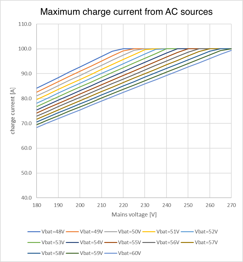
This is a MAXIMUM theoretical charging current, and additional limitations such as ambient temperature and airflow will also reduce real world output.
AC2 output is not programmable or relay controlled
AC2 output is internally hard wired to the AC input. There is no internal relay contact switch that is able to disconnect, or reconnect it via programming. There is also no delay from when the AC input is connected to when it flows through to the AC2 output.