ESS - Energy Storage System
Important
This information pertains specifically to the 'Dual Tracker' model (PMR482602020).
Grid feed-in using an Energy Storage System is not supported by the older 'Single Tracker' model (PMR482602000).
An Energy Storage System (ESS) is a specific type of power system that uses the Multi RS to work in conjunction with a grid connection. It is used to optimise the use of solar power, battery storage and grid import or export.
ESS can be configured to optimize self-consumption or to keep batteries charged.
When there is more PV power than is required to run loads, the excess PV energy is stored in the battery. That stored energy is then used to power the loads at times when there is a shortage of PV power. When the battery is full, then the excess PV energy can be exported to the grid.
You can choose how much battery capacity you want to keep in reserve. If your grid connection is reliable, you can use more of the battery and keep less in reserve. Conversely, if your grid connection is unreliable and experiences frequent outages, you may prefer to keep more battery energy in reserve.
The “Keep batteries charged” option keeps the batteries fully charged whenever possible. The batteries will only discharge during a grid outage when solar power is insufficient. As soon as grid power returns or sufficient solar power is available, the batteries will recharge automatically.
Note
Do not apply ESS settings in systems with a generator. See the Generator programming section when a generator is connected at the AC input.
The Multi RS can be configured as an Energy Storage System. In this setup, the device functions in grid-parallel mode, allowing energy to be sent back to the grid through the AC input terminals.
Note
For the Multi RS all ESS settings are configured in VictronConnect. There are limited configuration options in the ESS menu of a GX device.
To feed into the grid, you must select the appropriate grid code for your country within VictronConnect. In most cases, permission from the grid operator will be required before configuring an Energy Storage System to feed in.
If you do not have permission from your grid operator or if the installation does not meet the requirements for grid feed-in, set the grid code to 'None.' In this case, energy will not be fed back into the grid.
Important
Grid feed-in certification varies by country for the Multi RS, and it is not currently certified in all countries.
Do not assume the Multi RS is certified or permitted for grid export in your country simply because its grid code is listed in the drop-down.
Always check for current certificates for this product. These are available in the Downloads & Support section of the website.
Use VictronConnect to configure the Multi RS for ESS as below:
From the main settings page select the ESS settings page.
|
|
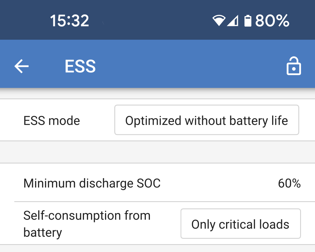
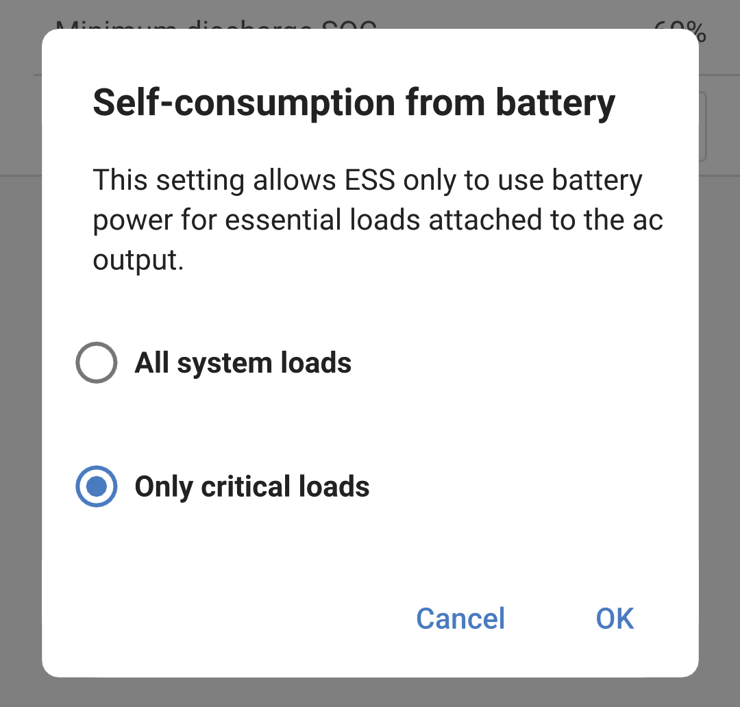
Self-consumption from battery options:
|
|
Note
Grid code settings require a password for protection against unauthorized interference.
After setting a grid code for the first time, it cannot be deactivated or modified without a password. If you need assistance changing your grid code, please contact your installer.
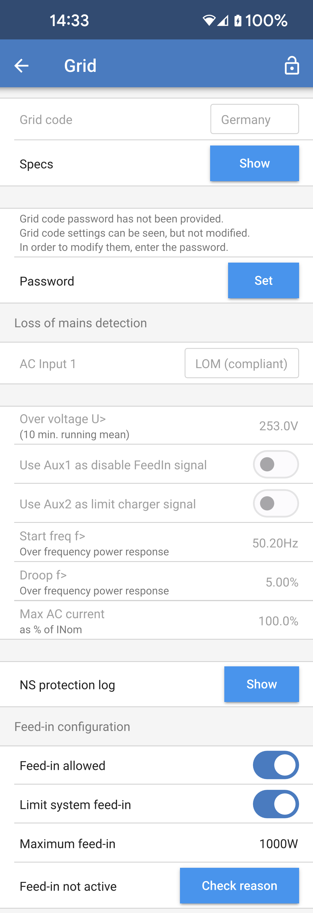
Navigate to the Grid settings page, choose an appropriate grid code for your area, and select it. Depending on your selection, additional options may become available, which may vary by region. In this example, we will use Germany as the selected grid code. Certain settings will appear greyed out and cannot be modified without setting the grid code password. Beware not to alter these settings unless instructed by your grid operator.
Loss of mains detection: Most of these settings are typically greyed out and are intended for informational purposes only. The values are defined by the selected grid code.
Feed-in configuration.
|
|
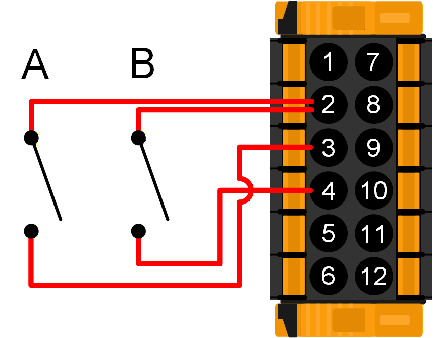
If the grid code requires external control of charging power or to disable grid feed-in, the contacts can be wired to the Aux_IN terminals of the User I/O connector. Three-phase systems require contact wiring to only one unit’s I/O connector. The contact state is then shared with and replicated by all other units in the system. NoteNot all grid codes support the use of Aux inputs. As an example, for the German grid code, the Aux_IN terminals are used as below:
|
|