Connection Overview
The illustration shows the front panel connectors with a description for each one in the table below.
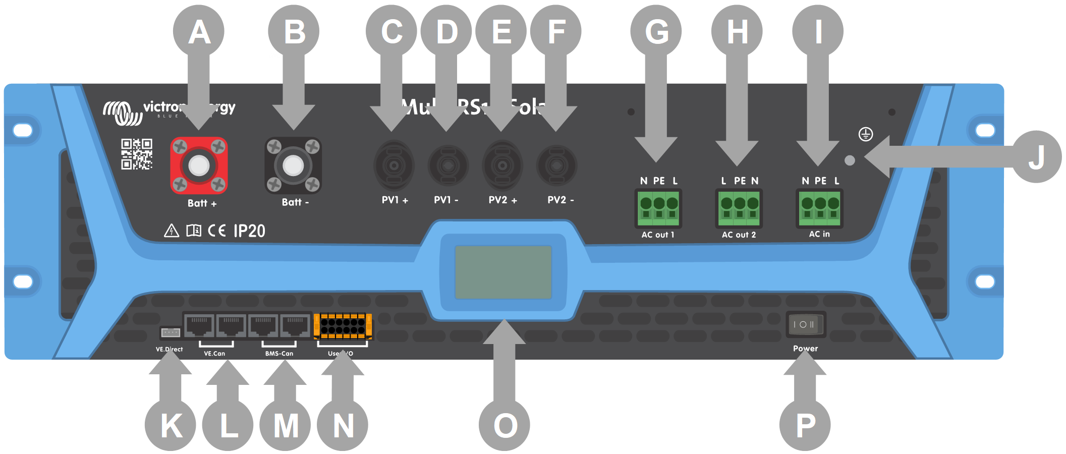
Table 1. Description of the front panel connectors
Letter | Name | Description |
|---|---|---|
A | Battery + | Battery positive connector |
B | Battery - | Battery negative connector |
C | PV1 + | PV array 1 positive connector |
D | PV1 - | PV array 1 negative connector |
E | PV2 + | PV array 2 positive connector |
F | PV2 - | PV array 2 negative connector |
G | AC Out 1 | AC Output 1 |
H | AC Out 2 | AC Output 2 |
I | AC In | AC Input |
J | Ground lug | Chassis grounding lug |
K | VE.Direct | VE.Direct connector |
L | VE.Can | VE.Can Canbus connector pair |
M | BMS-Can | BMS-Can Canbus connector pair |
N | User I/O | Removable user I/O connector. See chapter for pinout description |
O | Display | User LCD display |
P | Power Switch | Power on/off charger only switch |