3. Installation
3.1. Installation location
| To ensure a trouble free operation of the Multi RS19 Solar, it must be used in locations that meet the following requirements: a) Avoid any contact with water. Do not expose the product to rain or moisture. b) Install the Multi RS19 Solar upright and mounted horizontally in a 19" rack cabinet. Ensure 1U clearance above and below it. c) The Multi RS19 Solar must be installed on a non-flammable surface and the construction materials surrounding the installation should also be non-flammable. d) Do not place the unit in direct sunlight. Ambient air temperature should be between -40°C and 65°C (humidity < 95% non-condensing). e) Do not install the Multi RS19 Solar in an environment where the air could be contaminated with particulate matter such as soot, dust or salt. For example, conductive soot from the exhaust of a diesel generator could be drawn into the unit and cause short circuits inside it. f) Do not install the Multi RS19 Solar where flammable or corrosive gases or vapours could come near the installation. g) Do not obstruct the airflow through the Multi RS19 Solar. h) If the Multi RS19 Solar is installed in an area used for general storage, ensure that no flammable materials such a cardboard boxes are stored close to the installation. Ensure that the end user is aware of these requirements. | |
| The Multi RS19 Solar contains potentially dangerous voltages. It should only be installed under the supervision of a suitable qualified installer with the appropriate training, and subject to local requirements. Please contact Victron Energy for further information or necessary training. | |
| Excessively high ambient temperatures will result in the following:
Never position the Multi RS19 Solar directly above lead-acid batteries. The Multi RS19 Solar must be installed upright and horizontally in a 19" rack cabinet. | |
| For safety purposes, the Multi RS19 Solar should be installed in a heat-resistant environment. Any presence of: e.g. chemicals, synthetic components, curtains or other textiles, etc., in the immediate vicinity should be prevented at all times. | |
| Never connect batteries directly to the Multi RS19 Solar. Always ensure that adequate circuit protection is installed between the batteries and the Multi RS19 Solar. | |
| Batteries shall have a flammability class of HB or better. | |
| Each system requires a method of disconnecting the AC and DC circuits. If the overcurrent protection device is a circuit breaker, it can also serve as the disconnect. If fuses are used, separate disconnect switches are required between the source and the fuses. |

The Multi RS19 Solar is a 19" rack mountable unit. It is intended to be installed in a standard 19" rack mounting cabinet.
The cabinet should allow unobstructed air flow through the Multi RS19 Solar from the front to the back.
It's advisable to leave at least a 1U space above and below the unit to aid in cooling. If components within the cabinet are in contact with one another they'll exchange unwanted heat between them.
Cable runs between the batteries and the Multi RS19 Solar should be kept as short as possible to minimise voltage drop.
3.2. Connection Overview
The illustration shows the front panel connectors with a description for each one in the table below.
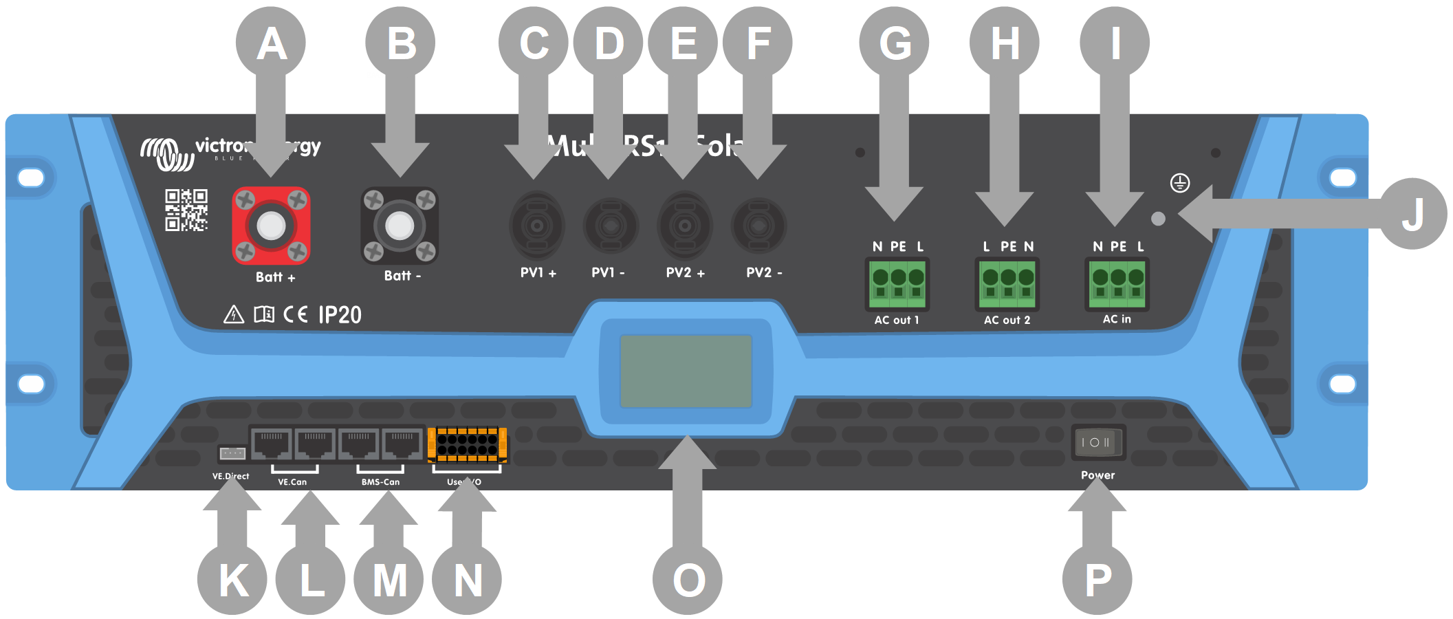
Letter | Name | Description |
|---|---|---|
A | Battery + | Battery positive connector |
B | Battery - | Battery negative connector |
C | PV1 + | PV array 1 positive connector |
D | PV1 - | PV array 1 negative connector |
E | PV2 + | PV array 2 positive connector |
F | PV2 - | PV array 2 negative connector |
G | AC Out 1 | AC Output 1 |
H | AC Out 2 | AC Output 2 |
I | AC In | AC Input |
J | Ground lug | Chassis grounding lug |
K | VE.Direct | VE.Direct connector |
L | VE.Can | VE.Can Canbus connector pair |
M | BMS-Can | BMS-Can Canbus connector pair |
N | User I/O | Removable user I/O connector. See chapter for pinout description |
O | Display | User LCD display |
P | Power Switch | Power on/off charger only switch |
3.3. Solar array configuration
Caution
Always use genuine Staubli MC4 connectors for the PV connections to the Multi RS19 Solar.
There are many other brands available, but some manufacturing variations mean that they may make poor contact and cause excessive heat. There are also inferior brands on the market which will likely cause serious problems.
Caution
When the PV array is exposed to light, it supplies DC voltage to the Multi RS19 Solar.
Caution
The maximum rated voltage of the solar charger is 450 V. A PV overvoltage event will damage the solar charger. This damage is not covered by warranty.
In case the PV array is located in colder climates the PV array can output more than its rated Voc. Use the MPPT sizing calculator on the solar charger product page to calculate this variable. As a rule of thumb, keep an additional 10% safety margin.
The maximum operational input current for each tracker is 12 A.
MPPT PV inputs are protected against reverse polarity, to a maximum short circuit current of 16 A for each tracker.
Warning
BEWARE that the product warranty will be void if a PV array with a short circuit current larger than 16 A is connected in reverse polarity.
Caution
The Multi RS19 Solar must keep the individual tracker inputs isolated from each other. That means one solar PV array per input, do not attempt to connect a single array to both tracker inputs.
When the MPPT switches to float stage it reduces battery charge current by increasing the PV Power Point voltage.
The maximum open circuit voltage of the PV array must be less than 8 times the minimum battery voltage when at float.
For example, where a battery has a float voltage of 54.0 volts, the maximum open circuit voltage of the connected array cannot exceed 432 volts.
Where the array voltage exceeds this parameter the system will give a "Over-charge Protection" error and shut down.
To correct this, either increase the battery float voltage, or reduce PV voltage by removing PV panels from the string to bring the voltage back within specification.
Multi RS19 Solar example PV configuration
Notice
This is an example of an array configuration. The decision on the specific array configuration, sizing and design for your system should be made in consultation with your system designer.
Tip
The PV array power can be over sized to be more than 3kW per tracker, but the MPPT trackers will limit the PV power to 3kW each.
Panel Type | Voc | Vmpp | Isc | Impp | # of panels per tracker | Maximum string voltage | Maximum string power | Total Power |
|---|---|---|---|---|---|---|---|---|
Victron 305 W (60 cell) | 39.7 V | 32.5 V | 10.27 A | 9.38 A | Tracker 1 - 10 panels | 397 V | 3050 W | 5930 W |
Victron 360 W (72 cell) | 47.4 V | 38.4 V | 10.24 A | 9.38 A | Tracker 2 - 8 panels | 379.2 V | 2880 W |
3.4. MPPT grounding, detection of PV array insulation faults & Earth fault alarm notification
The Multi RS19 Solar will test for sufficient resistance isolation between PV+ and GND, and PV- and GND.
In the event of an isolation resistance below the threshold (indicating an earth fault), the inverter shuts down and disables the ac outputs. The MPPT keeps charging the battery as this has no impact on safety due to the isolation on the battery side.
If an audible alarm and/or email notification of this fault is required, then you must also connect a GX device. Email notifications require an internet connection to the GX device and a VRM account to be configured.
The positive and negative conductors of the PV array must be isolated from ground.
Ground the frame of the PV array to local requirements.
The ground lug on the chassis of the Multi RS19 Solar should be connected to the common earth.
The conductor from the ground lug on the chassis of the Multi RS19 Solar to earth should have at least the cross-section of the conductors used for the PV array.
When a PV resistance isolation fault is indicated, do not touch any metal parts and immediately contact a suitably qualified technician to inspect the system for faults.
The battery terminals are galvanically isolated from the PV array. This ensures that PV array voltages cannot leak to the battery side of the system in a fault condition.
3.5. Cable connection sequence
First: Confirm correct battery polarity before connecting the battery cables, connect the battery.
Second:if required, connect the remote on-off, and programmable relay, and communications cables
Third:: Confirm correct PV polarity, and then connect the solar array (if incorrectly connected with reverse polarity, the PV voltage will drop, the controller will heat up but will not charge the the battery).
3.6. Battery and cable requirements
In order to utilize the full capacity of the Multi RS19 Solar, batteries with sufficient capacity and battery cables with sufficient cross section should be used. The use of undersized batteries or battery cables will lead to:
Reduction in system efficiency
Unwanted system alarms or shutdowns
Permanent damage to the system
The battery connection terminals on the Multi RS19 Solar are Amphenol SurLok Plus.
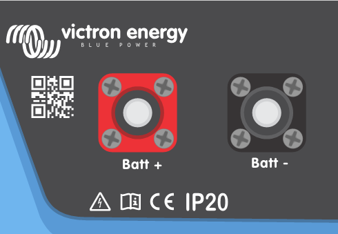
The appropriate 25mm2 plugs should be used to make the battery connections. The plugs should be crimped onto 25mm2 cable.
Amphenol SurLok Plus plugs
Connector Designation | Colour | Orientation | Amphenol part number |
|---|---|---|---|
Battery positive | Red | Right Angle | SLPPA25BSR |
Battery positive | Red | Straight | SLPIPA25BSR |
Battery negative | Black | Right Angle | SLPPA25BSB |
Battery negative | Black | Straight | SLPIPA25BSB |
Battery cable and fuse requirements
Cable length 0 - 2m | Cross sectional area: 25mm2 |
Recommended DC fuse | 125A |
Install a DC switch to a main DC fuse in the system. Only install the main DC fuse after all of the necessary DC connections have been made.
Do not connect or disconnect the Amphenol connectors when the DC system is powered. Remove the main DC fuse before disconnecting the Amphenol connectors.
Warning
Consult the battery manufacturer recommendations to ensure the batteries can take the total charge current of the system. The decision on battery sizing should be made in consultation with your system designer.
3.7. Battery connection procedure
Warning
Specific care and attention must be taken when making the battery connections. Correct polarity must be confirmed with a multimeter before connection. Connecting a battery with incorrect polarity will destroy the Multi RS19 Solar and is not covered by warranty.
Connect the negative battery cable first then connect the positive cable.
Push the Amphenol SurLok cable plug onto the receptacle on the Multi. Apply firm pressure until you hear a click, then the plug is latched onto the receptacle.
3.7.1. BMS-Can port
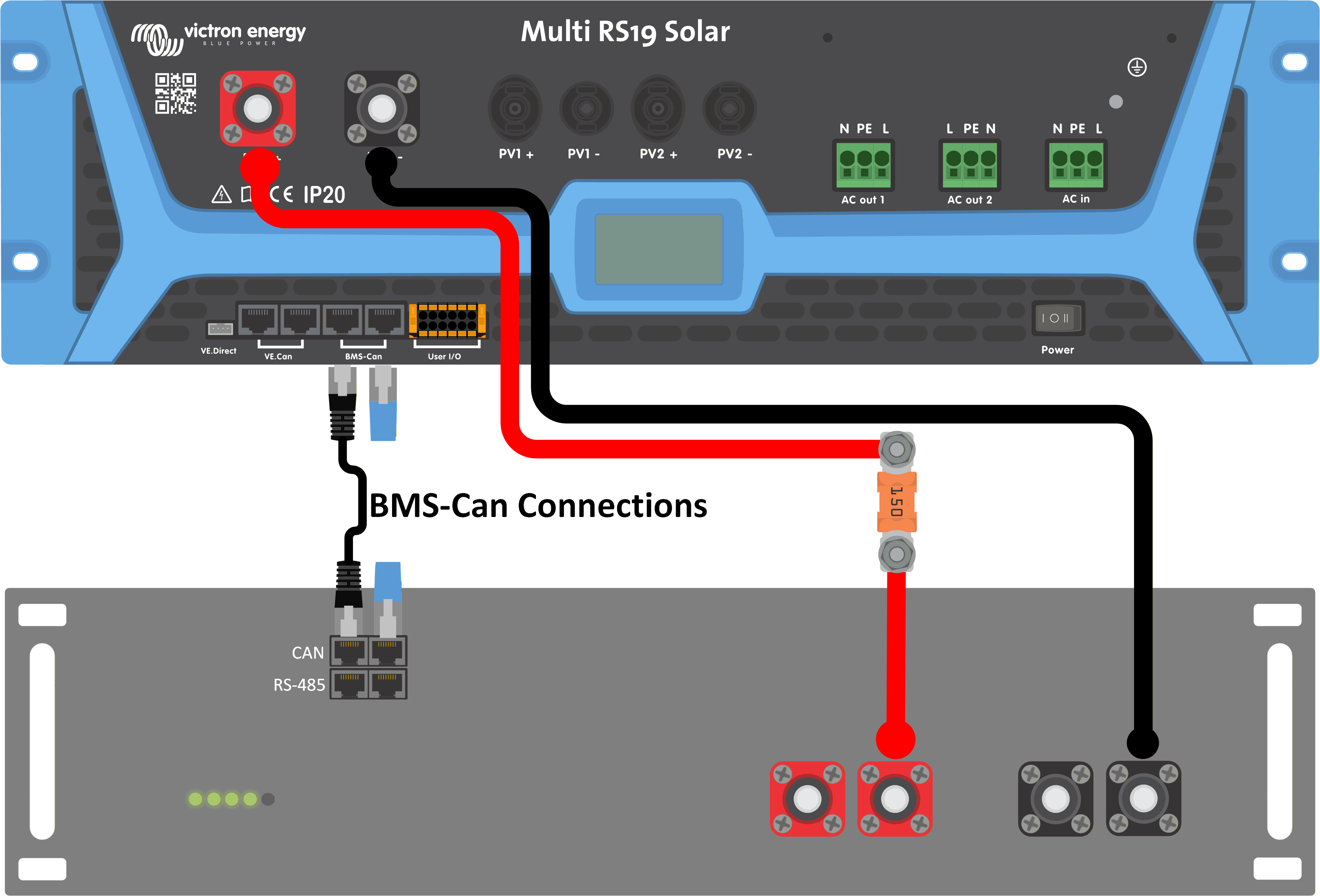
The BMS-Can port provides a 500 kbit/s data connection to the BMS of managed batteries supporting the CAN-bus BMS LV protocol.
It is only intended to be used in small systems without a GX device and a single Multi RS19 Solar.
Limitations
The data rate is fixed at 500kbit/s. It cannot be adjusted to 250kbit/s.
The BMS-Can port on the Multi RS19 Solar should only be used in small systems which don't have a GX device. If a GX device is present in the system, then use the BMS-Can port on the GX device.
There are no DVCC settings available in the Multi RS19 Solar. Connect the BMS to the BMS-Can port of a GX device to use these features.
In most cases there is a GX device in the system, so the battery's BMS communication port should be connected to the BMS-Can port on the GX device.
A Victron Lynx BMS should be connected to the VE.Can port in any case, whether a GX device present or not.
Caution
Do not use the BMS-Can port if there is more than one Multi RS19 Solar in the system such as three phase systems. Use the BMS-Can port on the GX device.
Caution
Do not use the BMS-Can port of the Multi RS19 Solar in systems which have a GX device. Connect managed batteries to the BMS-Can port on the GX device.
Caution
Do not connect cables between the BMS-Can port on the Multi RS19 Solar and the GX device.
In systems without a GX device, the battery's BMS can be connected directly to the BMS-Can port of the Multi RS19 Solar. |
| |
If a GX device is present in the system, then the battery's BMS should be connected to the BMS-Can port of the GX device. Connect the GX device to the Multi RS19 Solar using the VE.Can ports. | 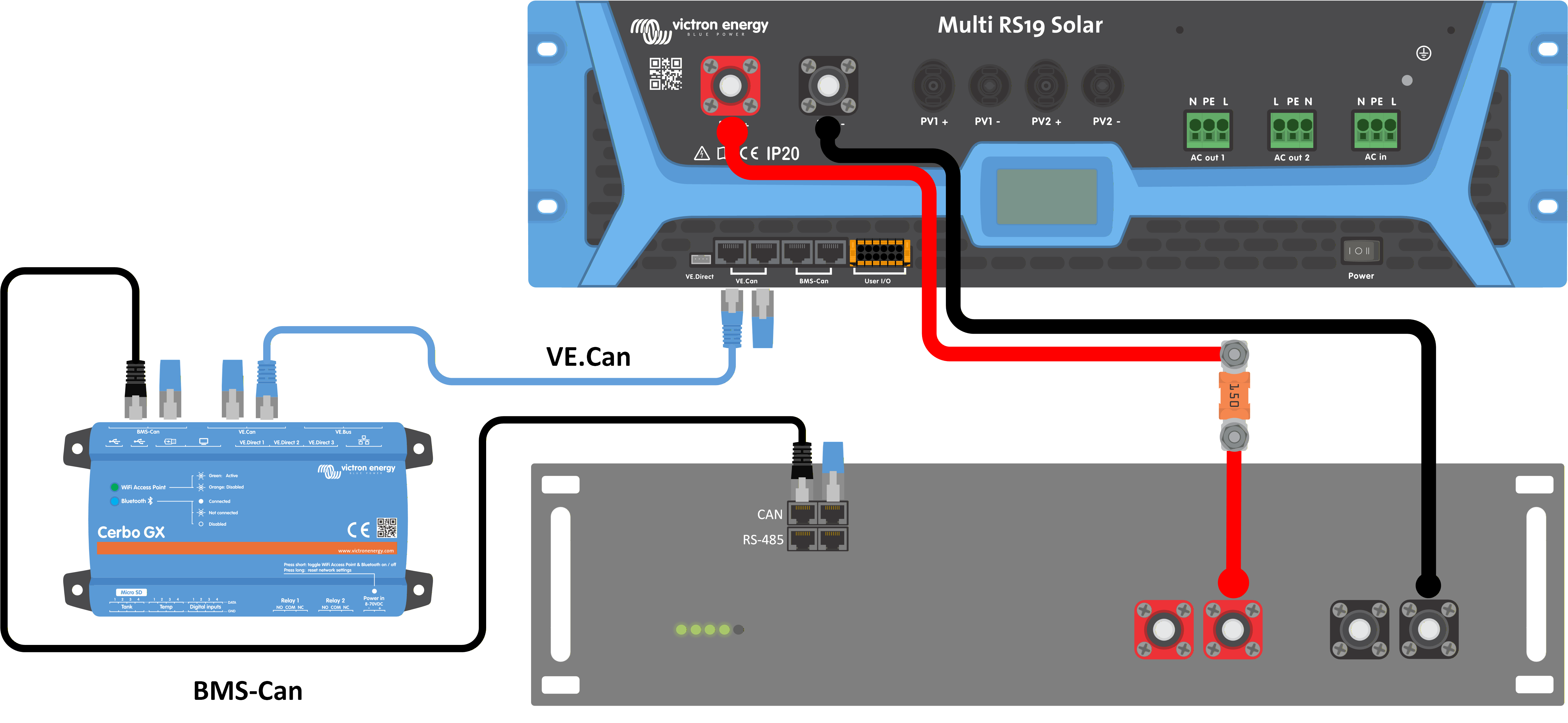 |
Configuration
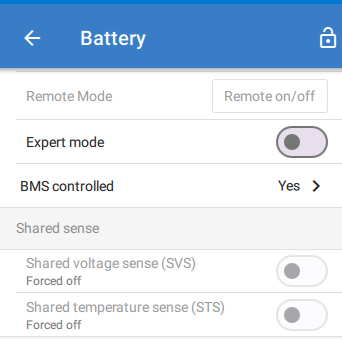
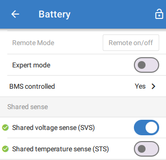
When a managed battery is connected to the BMS-Can port, the shared sense options will appear in the Battery settings menu in VictronConnect.
Note
If there is no managed battery connected to the BMS-Can port of the Multi RS19 Solar, then these settings will not be available.
Note
If a managed battery is connected to the BMS-Can port of a GX device, these settings will not appear here. In that case, the settings will appear in the settings menu of the GX device.
If a supported battery type is connected to the BMS-Can port of the Multi RS19 Solar, then the settings will appear, but they will be set according to the requirements of that particular battery type and will be greyed out. You will not be able to change these settings, but they are there for you to see how they have been configured. See the battery compatibility list: https://www.victronenergy.com/live/battery_compatibility:start |
| |
If an unsupported battery type is connected to the BMS-Can port of the Multi RS19 Solar, then the settings will appear. You'll need to adjust these settings according to the specifications of the battery manufacturer. |
|
3.8. Connection of AC cabling
Warning
This is a safety class 1 product (supplied with a ground terminal for safety purposes). Its AC input and/or output terminals and/or chassis grounding point on the front of the Multi RS19 Solar must be connected to an uninterruptible ground connection for safety purposes.
In a fixed installation, an uninterruptible grounding can be secured by means of the grounding wire of the AC input. Otherwise the casing must be grounded.
This product is provided with a ground relay that automatically connects the Neutral output to the chassis if no external AC supply is available. If an external AC supply is provided, the ground relay H will open before the input safety relay closes. This ensures the correct operation of an earth leakage circuit breaker that is connected to the output.
In a mobile installation (for example, with a shore current plug), unplugging the shore connection will simultaneously disconnect the grounding connection. In that case, the casing must be connected to the vehicle chassis.
A fuse or automatic circuit breaker rated to support the expected load must be installed in series with the output, and the cable cross-section must be sized accordingly. The circuit breaker must be rated at 50 A or less.
Note
The Multi RS19 Solar does not provide full galvanic isolation between PV DC input and AC terminals.
In accordance with IEC62109-1 and IEC62109-2, an internal Residual Current Monitoring Unit (RCMU) ensures that no DC current appears on the AC side. Both DC and AC fault current component types are monitored. If a fault is detected, the inverter will be automatically shut down, disconnecting the AC system.
Ensure that your AC installation meets local regulations for residual current protection. Please refer to the RCD Information on Multi RS document for further guidance.
The AC connection terminal blocks can be found on the front panel.
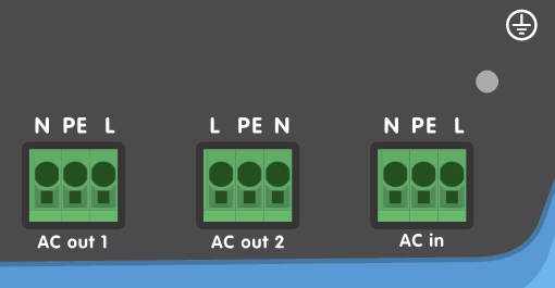
The AC connector block is a push-in spring connector.
Conductor insulation should be stripped to expose 15mm of bare conductor.
Push the conductor into the round hole of the terminal block position. Multi-stranded conductors may require a small screwdriver to be inserted into the square hole to release the spring tension which will ease insertion of the conductor.
The maximum conductor cross sectional area is 6mm2 (8 AWG).
Warning
DO NOT reverse the polarity of the neutral and line conductors when connecting AC cabling.
AC-out-1 The AC output cable can be connected directly to the terminal block 'AC-out'. From left to right: "N" (neutral) - "PE" (earth) - "L" (phase). With its PowerAssist feature the Multi RS19 Solar can add up to 25 A to the output during periods of peak power requirement. The Multi RS19 Solar can provide a maximum throughput of up to 50 A to the loads. The AC input relays are limited to 50 A, and the inverter can contribute up to 25 A continuous at best conditions (when it gets hotter this figure will be reduced).
Warning
The AC output terminals must be protected from overload by a circuit breaker rated at 50 A or less, and cable cross-section must be sized accordingly.
AC-out-2 A second output is available that disconnects its load in the event of battery-only operation. From left to right: "L" (line) - "PE" (earth) - "N" (neutral). On these terminals, equipment is connected that may only operate if AC voltage is available on AC-in-1, e.g. an electric boiler or an air conditioner. The load on AC-out-2 is disconnected immediately when the inverter/charger switches to battery operation. After AC power becomes available on AC-in-1, the load on AC-out-2 will be reconnected with a delay of approximately 2 minutes.
AC-in The AC input cable can be connected to the terminal block 'AC–in'. From left to right: "N" (neutral) - "PE" (earth) - "L" (line). The AC input must be protected by a circuit breaker rated at 50 A or less, and cable cross-section must be sized accordingly.
Warning
If the input AC supply is rated at a lower value, the circuit breaker should be down sized accordingly.
3.9. VE.Direct
This can be used to connect a PC/laptop to configure the inverter with a VE.Direct to USB accessory. Can also be used to connect a Victron GlobalLink 520 to allow for remote data monitoring.
Note
The VE.Direct port on the Multi RS19 Solar cannot be used to connect to a GX device, and the VE.Can connection must be used instead.
3.10. VE.Can
The VE.Can ports can be used to connect to other devices, such as:
A GX device for monitoring and communication.
Other Multi RS19 Solar devices forming a three phase system.
An energy meter such as the Victron VM-3P75CT.
Additional MPPT's like the MPPT RS or other VE.Can MPPT controllers.
VE.Can terminators should always be installed in the devices at both ends of the VE.Can network.
3.11. Bluetooth
Used to connect to the device via VictronConnect for configuration.
Note that this Bluetooth interface is not compatible with VE.Smart Networking (i.e Smart Battery Sense).
3.12. User I/O
The user I/O terminal block is located on the bottom left hand side of the front panel.
The terminal block can be removed to make connecting small wires easier. To release it, push both orange levers (top and bottom of the connector) to the left.
Connections are made by pushing the wire into the hole. In the "TOP" orientation, the wire can be released by pushing down the orange tab next to the hole with a small flat blade screwdriver.
Note
From the factory, there is a wire link installed in the Remote_H and Remote_L position. This will enable the Multi RS19 Solar to operate by default. If this wire link, or the connector is removed then the Remote_H and Remote_L terminals become open circuit, and the Multi RS19 Solar will not turn on.
The diagram below shows the pinout of the connector and the function of each pin. The functions are also printed on the side of the connector itself.
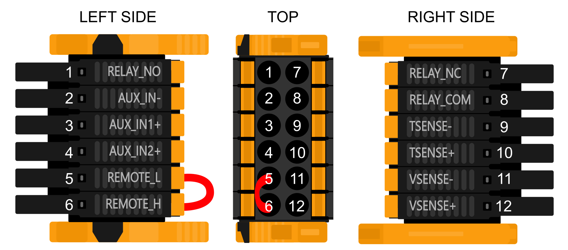
Pin number | Pin name | Description |
|---|---|---|
1 | RELAY_NO | Programmable relay Normally Open connection |
2 | AUX_IN- | Common negative for programmable auxiliary inputs |
3 | AUX_IN1+ | Programmable auxiliary input 1 positive connection |
4 | AUX_IN2+ | Programmable auxiliary input 2 positive connection |
5 | REMOTE_L | Remote on/off connector Low |
6 | REMOTE_H | Remote on/off connector High |
7 | RELAY_NC | Programmable relay Normally Closed connection |
8 | RELAY_COM | Programmable relay Common connection |
9 | TSENSE- | Temperature Sensor negative |
10 | TSENSE+ | Temperature Sensor positive |
11 | VSENSE- | Voltage Sensor negative |
12 | VSENSE+ | Voltage Sensor positive |
3.12.1. Remote H and L terminals
There are two terminals marked REMOTE_H and REMOTE_L.
The default function of these terminals is to switch the Multi RS19 Solar on or off remotely.
Note
From the factory, these two terminals are connected together with a wire link. This enables the Multi RS19 Solar to turn on when its main physical switch is on.
To use the terminals for remote connections, the wire link should be removed.
These two contacts can be configured for either remote on/off (default), or for 2-wire BMS mode.
When multiple units are combined in a system — for example in a three-phase setup — you can connect the contact wires to any single unit. The contact’s state is then shared with the rest of the system through the VE.Can connections.
You only need to configure the unit which has the contact wires connected to it.
Remote on/off functionality:
The factory fitted wire link can be removed and then wires can be connected to an external switch contact. The switch contact can then be used to switch the Multi RS19 Solar on or off.
This is the default configuration in VictronConnect, no configuration changes are necessary on a new unit. The configuration can be checked in Remote mode in the Battery settings menu.
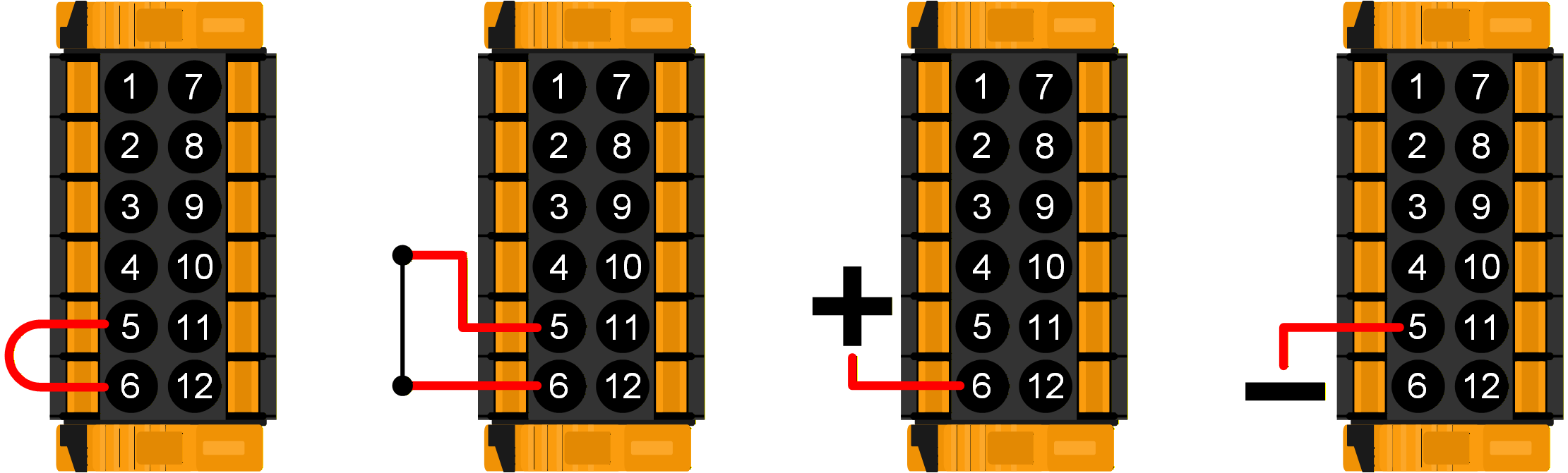
The Multi RS19 Solar will be switched on if the inputs are wired in one of the four ways pictured on the right.
|  |
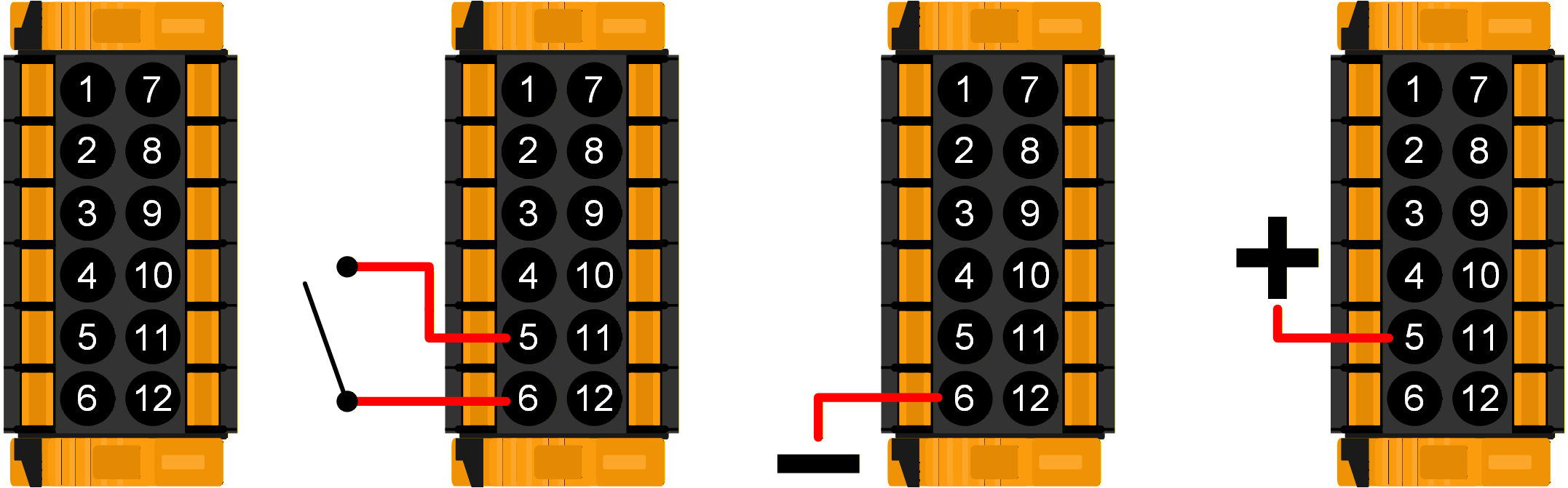
The Multi RS19 Solar will be switched off if the inputs are wired in one of the four ways pictured on the right.
|  |
2-wire BMS mode:
The REMOTE_H and REMOTE_L terminals can also be configured for interfacing with a 2-wire BMS. Two separate contacts on the BMS control whether the Multi RS19 Solar is allowed to charge or discharge. This is configured in VictronConnect, see Remote mode in the Battery settings menu.
Change the mode from "Remote on/off" to "2-wire BMS".
The diagrams below demonstrate what mode the Multi RS19 Solar will be in depending upon the state of the REMOTE_H and REMOTE_L terminals.
Note
In 2-wire BMS mode, if the REMOTE_H and REMOTE_L terminals are linked (and not connected to +48V), the Multi RS19 Solar will be on, but charging will be disabled.
The BMS' "Allow to charge" and "Allow to discharge" contacts are both closed. The REMOTE_H and REMOTE_L terminals are both pulled up to +48V through the BMS switch contacts. The Multi RS19 Solar operates normally, and is allowed to charge and discharge the battery. | 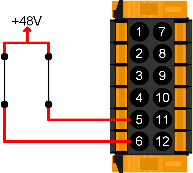 |
The BMS has opened its "Allow to charge" contact. The REMOTE_H is pulled up to +48V through the BMS contact and REMOTE_L terminal is open circuit (floating). The Multi RS19 Solar stops charging the battery from AC and/or solar sources, but continues to discharge the battery as normal. | 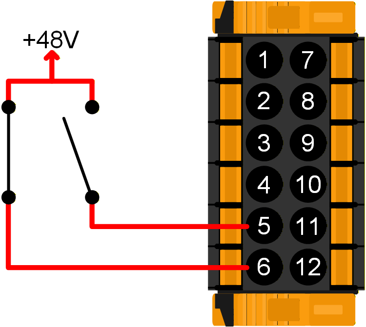 |
The BMS has opened its "Allow to discharge" contact. The REMOTE_L is pulled up to +48V through the BMS contact and REMOTE_H terminal is open circuit (floating). The Multi RS19 Solar stops discharging the battery, but continues to charge the battery from AC and/or solar sources if available. | 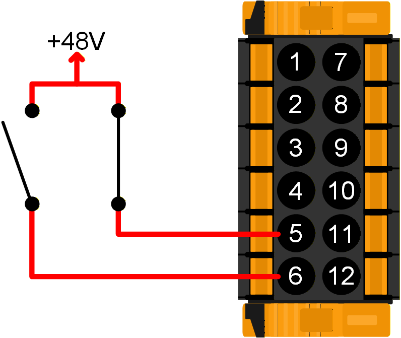 |
The BMS' "Allow to charge" and "Allow to discharge" contacts are both open. The REMOTE_H and REMOTE_L terminals are both open circuit (floating). Neither charging nor discharging is allowed, so the Multi RS19 Solar switches off. | 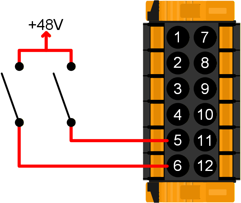 |
3.12.2. Programmable relay
There is one general-purpose, potential free (dry) relay contact which can be configured for various functions.
Use the Relay menu in VictronConnect to configure it.
The relay contacts are rated for 4A up to 35VDC and 1A at 70VDC.
Warning
Do not use the relay contact for any AC (230V) circuits.
In this example, the normally open relay contact is configured for starting and stopping a generator. | 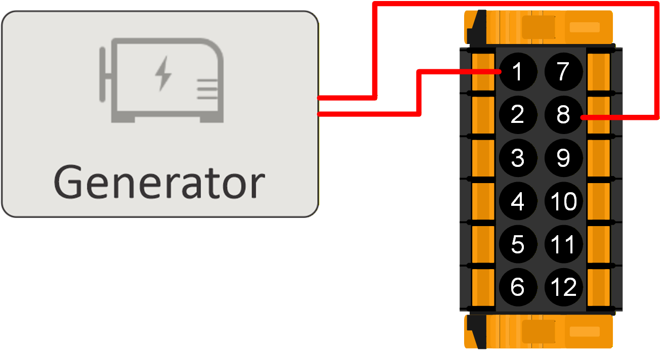 |
3.12.3. Voltage sense
To compensate for possible cable losses during charging, two sense wires can be connected directly to the battery or to the positive and negative distribution points. Use wire with a cross-section of 0,75mm². During battery charging, the charger will compensate the voltage drop over the DC cables up to a maximum of 1 Volt (i.e. 1V over the positive connection and 1V over the negative connection). If the voltage drop threatens to become larger than 1V, the charging current is limited in such a way that the voltage drop remains limited to 1V.
An example of the VSENSE+ and VSENSE- terminals connected to the battery terminals. A fuse close to the battery is recommended to protect the Voltage sense wires from any short circuits. | 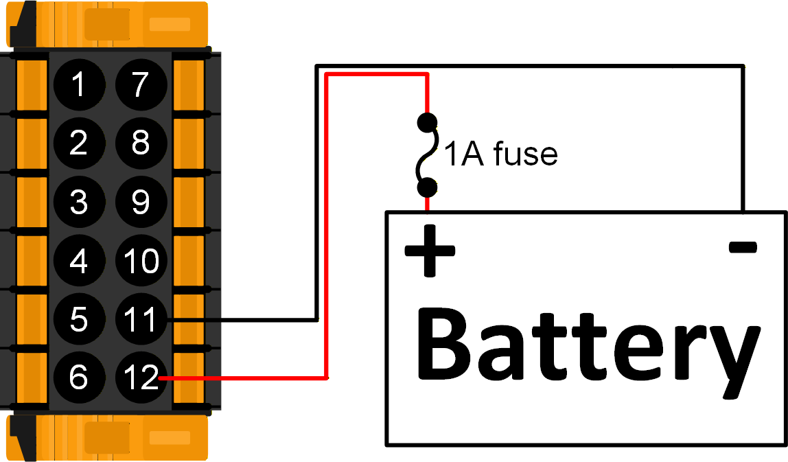 |
3.12.4. Temperature sensor
For temperature-compensated charging, the temperature sensor (supplied with the unit) can be connected. The sensor is isolated and must be fitted to the negative terminal of the battery. The temperature sensor can also be used for low temperature cut-off when charging lithium batteries. You can configure this in the Battery settings page in VictronConnect.
The supplied battery temperature sensor is connected to the battery negative terminal. NoteOnly use the temperature sensor which is supplied with the Multi RS19 Solar. | 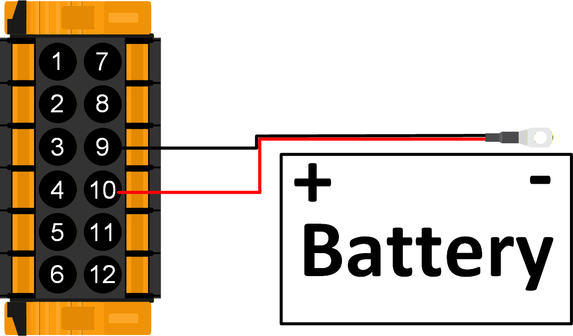 |
3.12.5. Auxiliary inputs
The Multi RS19 Solar is equipped with 2 digital input ports, they are labelled AUX_IN1+ and AUX_IN2+ on the removable terminal block, with AUX_IN- being the common terminal for both.
An AUX_IN+ input is considered active when it is connected to AUX_IN-.
Warning
Do not connect any of the AUX_IN terminals to the battery positive or negative.
The diagram on the right shows AUX_IN1 as active. | 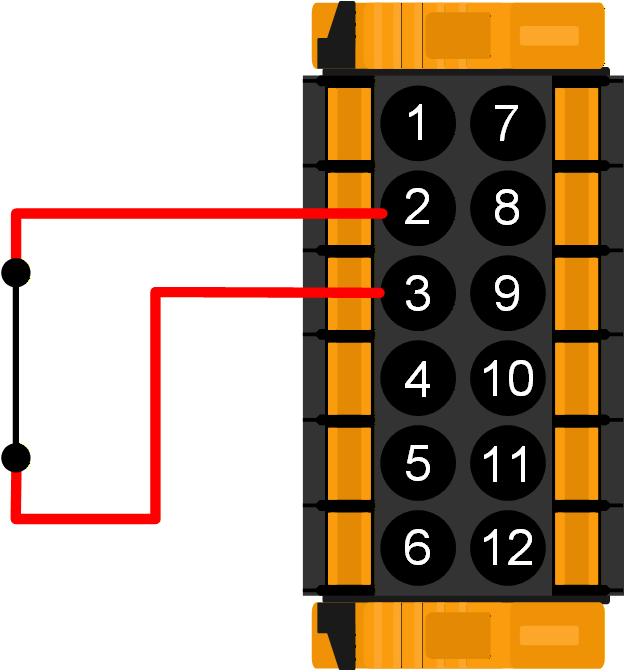 |
The diagram on the right shows AUX_IN1 as inactive. | 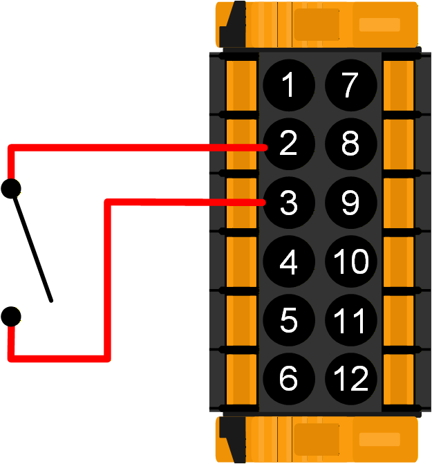 |
In VictronConnect, the Aux input settings page allows different functions to be configured.
Unused: The Aux input has no function.
AC IN connect: The AC input can be connected or disconnected as needed. For example, you can disable the AC input during expensive peak periods of a time-of-use tariff. Either an active signal or an inactive signal can be used to set the AC input connected state.
AC IN feed-in enable: In a grid parallel installation, the Aux input can be used to enable or disable grid feed-in. Either an active signal or an inactive signal can be used to set the feed-in state.
Safety switch: The Multi RS19 Solar only operates when the Aux input is active.
This can be used to remotely switch off the Multi RS19 Solar if the REMOTE_L and REMOTE_H terminals are configured for a 2-wire BMS.
It could also be used as a separate safety switch signal from another system which needs its own input.
Note
If the REMOTE_L and REMOTE_H terminals are in a state that switches the Multi RS19 Solar off, then this will override the Aux input Safety switch function, and it will remain off.
For example, if the REMOTE_H and REMOTE_L terminals are open circuit, then the Multi RS19 Solar will be switched off regardless of the state of the Aux input Safety switch
If the same function is assigned to both aux inputs then they will be treated as an AND function, so both will need to be active for the function to be recognized as active.
Note
Some grid codes require the auxiliary inputs to be used for charge power limiting or to prevent export. Any grid code functions will override functions defined in the Aux input settings and they will be greyed out.
3.13. Generator programming
The Multi RS19 Solar has a tolerance for irregularities on the AC input like fast frequency changes or voltage changes to improve reliability when connecting to generators.
Using a generator with the Multi RS19 Solar requires firmware version v1.11 or later.
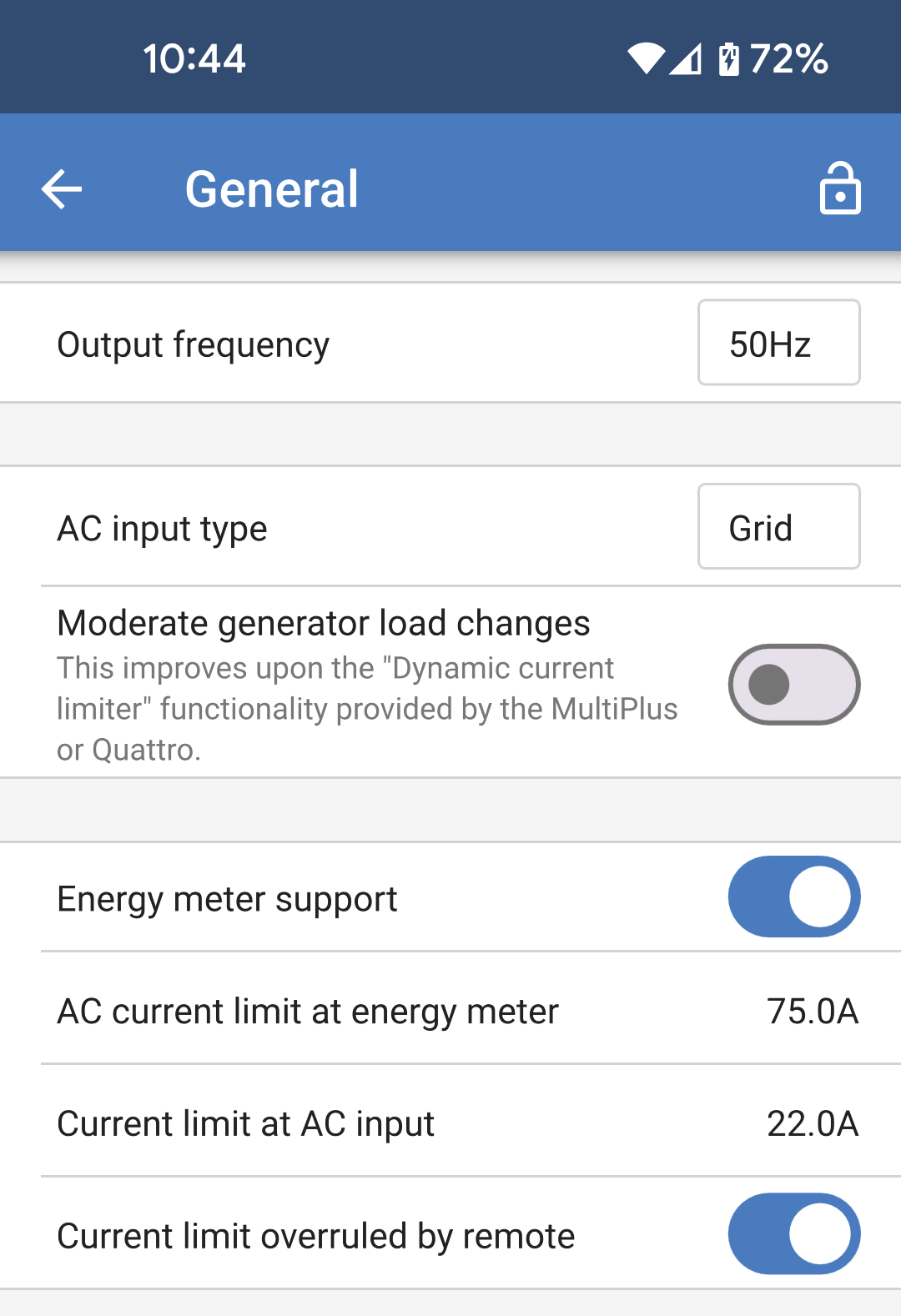
Set the following option on the General settings page:
|
|
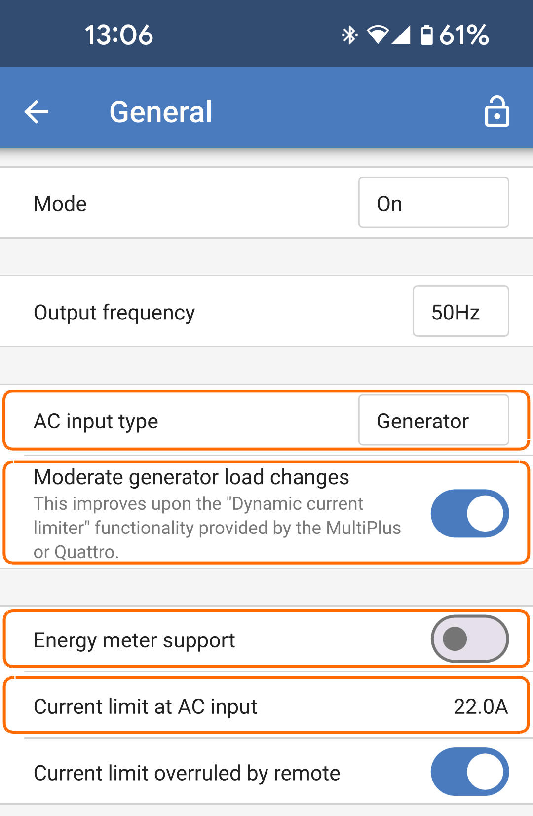
If no grid code is set then set the following on the Grid page:
|
|
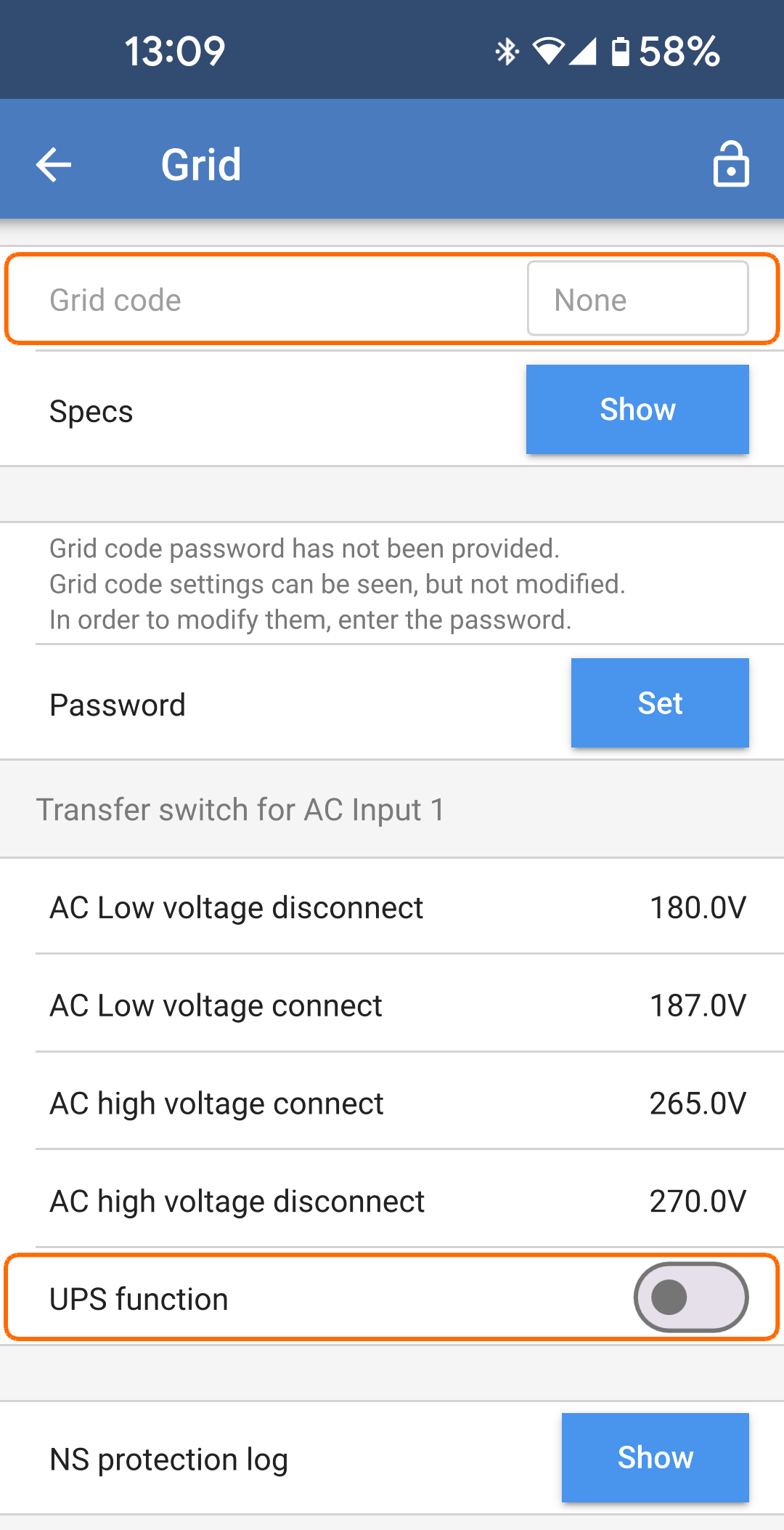
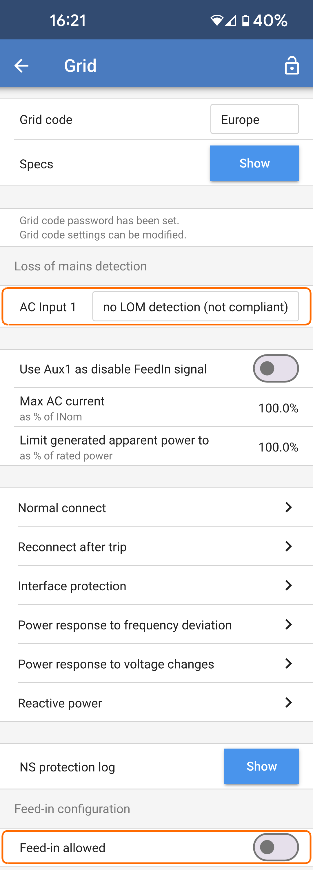
If a grid code is set then set the following two parameters on the Grid page:
|
|
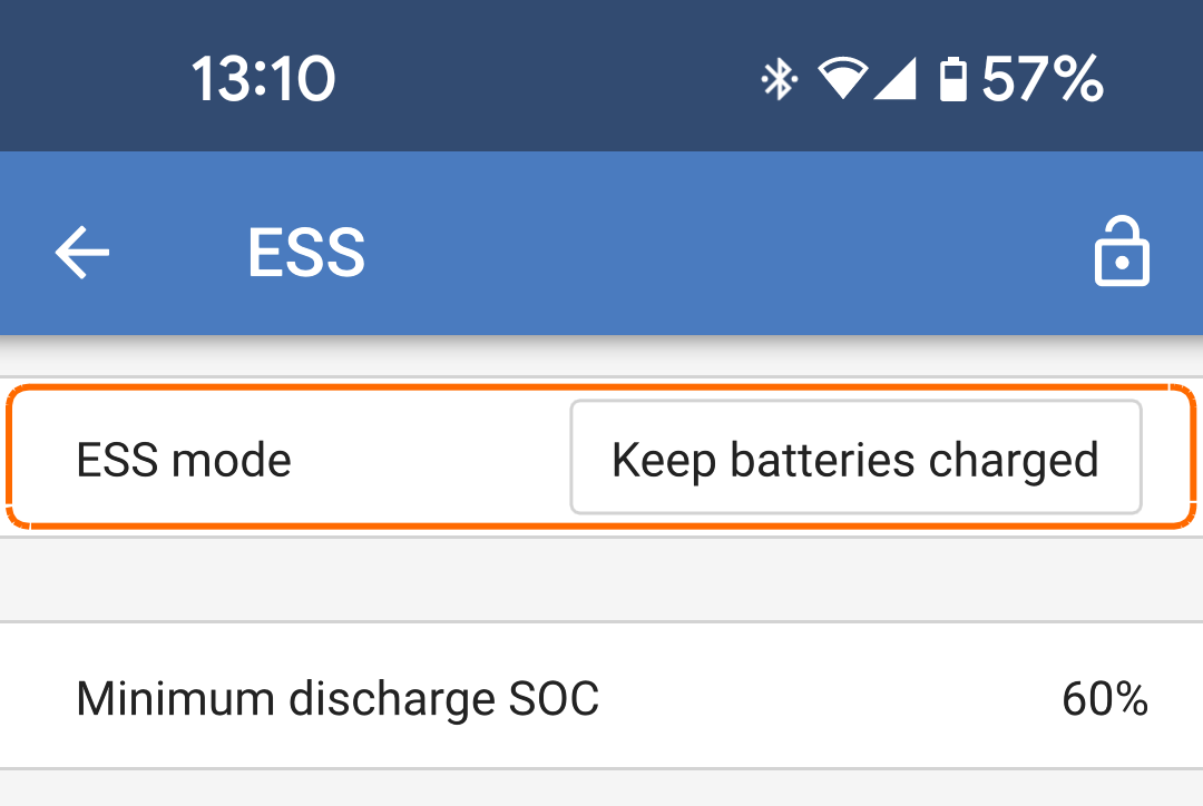
Ensure that the ESS mode is set to "Keep batteries charged". |
|
The programmable relay contact of the Multi RS19 Solar can be used to start and stop a generator. The setup is explained in the VictronConnect section.
See Limitations chapter for additional charging power limitations.
3.14. ESS - Energy Storage System
An Energy Storage System (ESS) is a specific type of power system that uses the Multi RS19 Solar to work in conjunction with a grid connection. It is used to optimise the use of solar power, battery storage and grid import or export.
ESS can be configured to optimize self-consumption or to keep batteries charged.
When there is more PV power than is required to run loads, the excess PV energy is stored in the battery. That stored energy is then used to power the loads at times when there is a shortage of PV power. When the battery is full, then the excess PV energy can be exported to the grid.
You can choose how much battery capacity you want to keep in reserve. If your grid connection is reliable, you can use more of the battery and keep less in reserve. Conversely, if your grid connection is unreliable and experiences frequent outages, you may prefer to keep more battery energy in reserve.
The “Keep batteries charged” option keeps the batteries fully charged whenever possible. The batteries will only discharge during a grid outage when solar power is insufficient. As soon as grid power returns or sufficient solar power is available, the batteries will recharge automatically.
Note
Do not apply ESS settings in systems with a generator. See the Generator programming section when a generator is connected at the AC input.
The Multi RS19 Solar can be configured as an Energy Storage System. In this setup, the device functions in grid-parallel mode, allowing energy to be sent back to the grid through the AC input terminals.
Note
For the Multi RS19 Solar all ESS settings are configured in VictronConnect. There are limited configuration options in the ESS menu of a GX device.
To feed into the grid, you must select the appropriate grid code for your country within VictronConnect. In most cases, permission from the grid operator will be required before configuring an Energy Storage System to feed in.
If you do not have permission from your grid operator or if the installation does not meet the requirements for grid feed-in, set the grid code to 'None.' In this case, energy will not be fed back into the grid.
Important
Grid feed-in certification varies by country for the Multi RS19 Solar, and it is not currently certified in all countries.
Do not assume the Multi RS19 Solar is certified or permitted for grid export in your country simply because its grid code is listed in the drop-down.
Always check for current certificates for this product. These are available in the Downloads & Support section of the website.
Use VictronConnect to configure the Multi RS19 Solar for ESS as shown on the following pages:
From the main settings page select the ESS settings page.
|
|
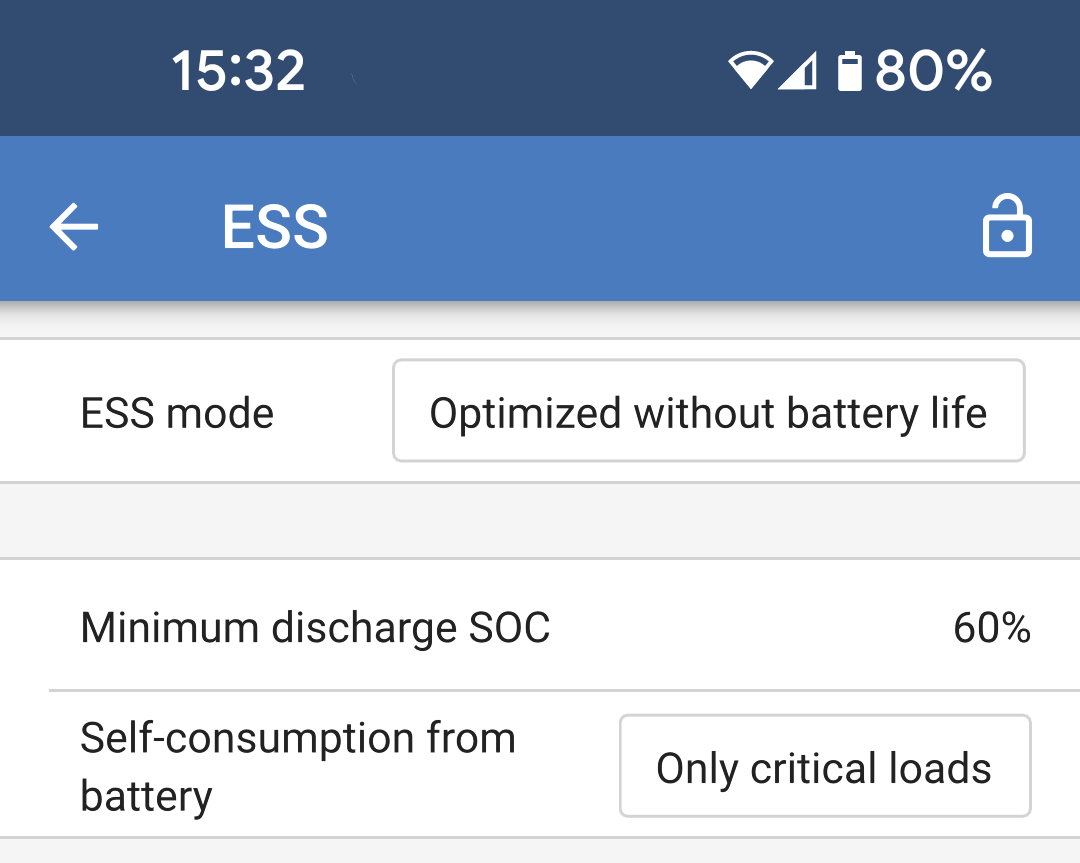
Self-consumption from battery options:
|
|
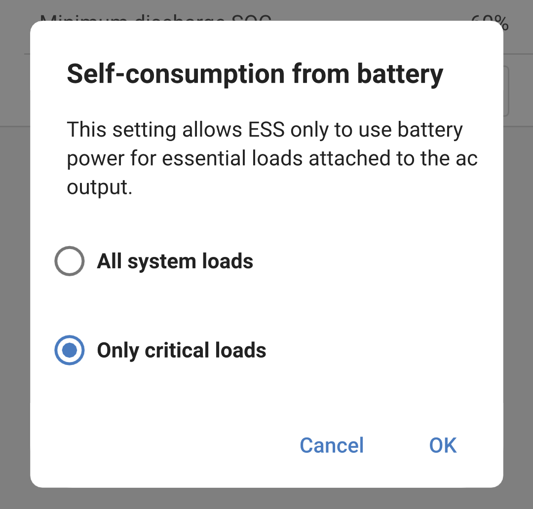
Note
Grid code settings require a password for protection against unauthorized interference.
After setting a grid code for the first time, it cannot be deactivated or modified without a password. If you need assistance changing your grid code, please contact your installer.
Navigate to the Grid settings page, choose an appropriate grid code for your area, and select it. Depending on your selection, additional options may become available, which may vary by region. In this example, we will use Germany as the selected grid code. Certain settings will appear greyed out and cannot be modified without setting the grid code password. Beware not to alter these settings unless instructed by your grid operator.
Loss of mains detection: Most of these settings are typically greyed out and are intended for informational purposes only. The values are defined by the selected grid code.
Feed-in configuration.
|
|
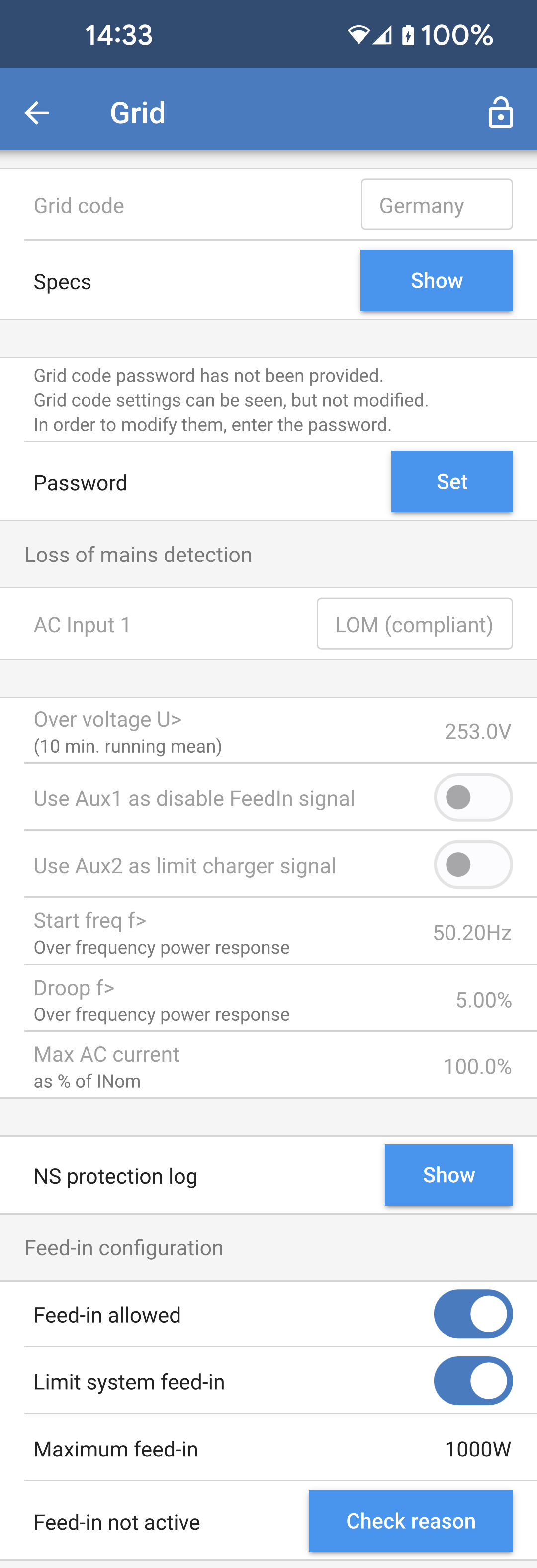
If the grid code requires external control of charging power or to disable grid feed-in, the contacts can be wired to the Aux_IN terminals of the User I/O connector. Three-phase systems require contact wiring to only one unit’s I/O connector. The contact state is then shared with and replicated by all other units in the system. NoteNot all grid codes support the use of Aux inputs. As an example, for the German grid code, the Aux_IN terminals are used as below:
|
|
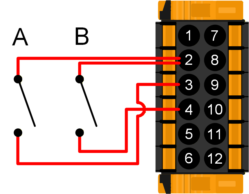
3.15. Connecting to external AC PV inverters
The Multi RS19 Solar includes a built in AC PV inverter detection system. When there is a feedback of AC PV (a surplus) from the AC-out connection port, the Multi RS19 Solar will automatically enable an AC output frequency adjustment.
While no further configuration is required, it is important that the AC PV inverter is configured correctly to respond to the frequency adjustment by reducing its output.
Note the 1:1 rule of AC PV inverter size to Multi RS19 Solar size, and minimum battery sizing applies. More information about these limitations are available in the AC Coupling manual, and this document is required reading if using an AC PV inverter.
The frequency adjustment range is not configurable, and includes a built in safety margin. Once the absorption voltage is reached, the frequency will increase. So it is still essential to include a DC PV component in the system for complete battery charging (i.e. float stage).
The PV inverter stop frequency (fstop) is 53.2Hz. This is not configurable.
It may be possible to adjust the power output response to various frequencies on your AC PV inverter.
The default configuration has been tested and works reliably with the Fronius MG50/60 grid code configuration.
3.16. PV Inverter configuration
The Multi RS19 Solar can be configured as a PV Inverter without the need for a battery bank. All PV energy will feed in to the grid through the AC input connection.
Note
To use this feature, your system will need to be grid-connected. You'll need to set a suitable grid code for your location and have the necessary permissions to sell power back to the grid.
Caution
Do not connect any loads or external PV inverters to the AC output 1.
Set a grid code for your region. See the Grid settings page for more information.
Set the following option on the ESS settings page:
|
|
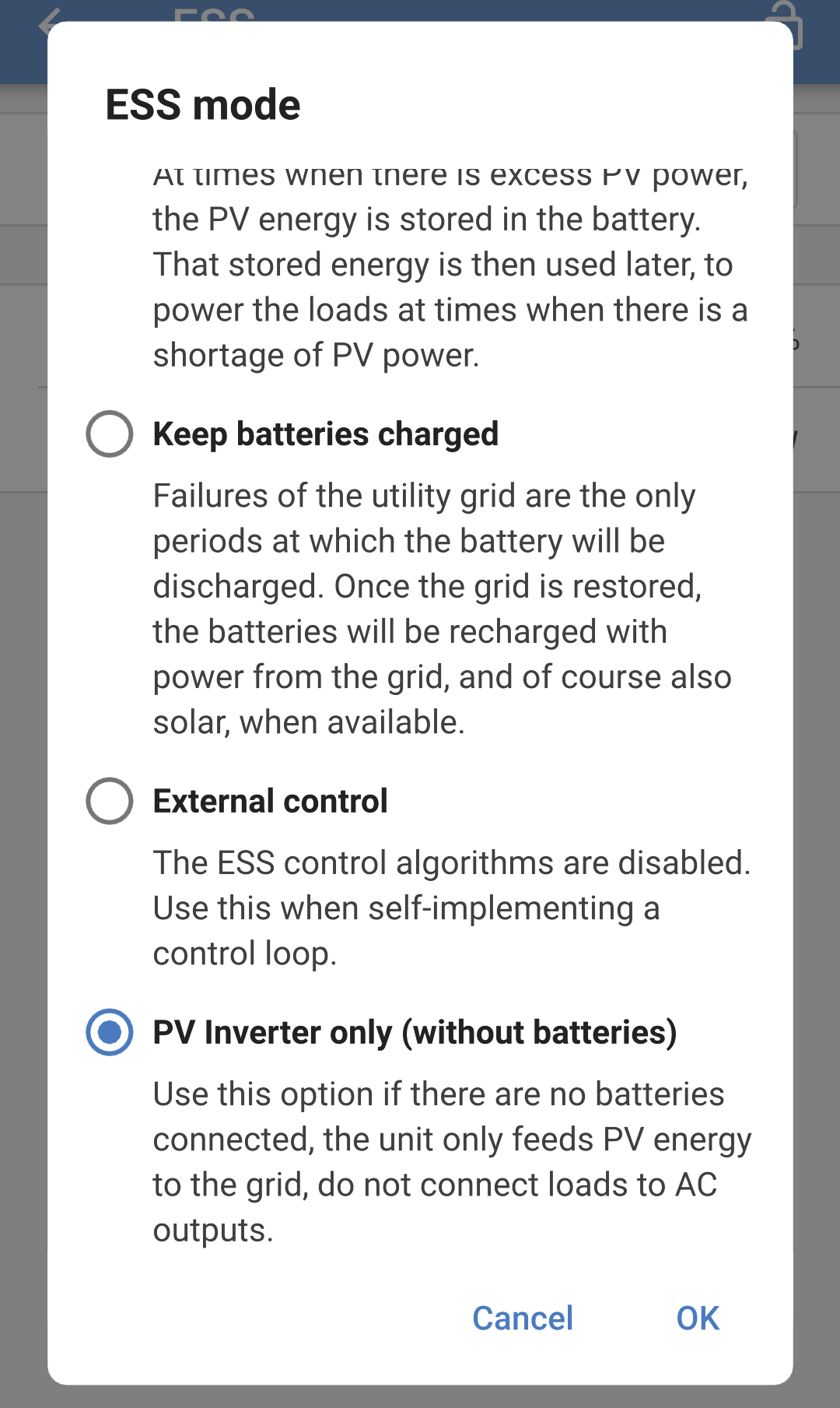
After setting "PV Inverter only mode (without batteries)", the following settings will be enforced:
System -> System configuration = Standalone
General -> Energy meter support = Disabled
AC input control -> Conditional AC input connection = Disabled
3.17. Connecting an external energy meter
The Victron VM-3P75CT energy meter can be used with the Multi RS19 Solar.
Note
Only the Victron VM-3P75CT energy meter is supported.
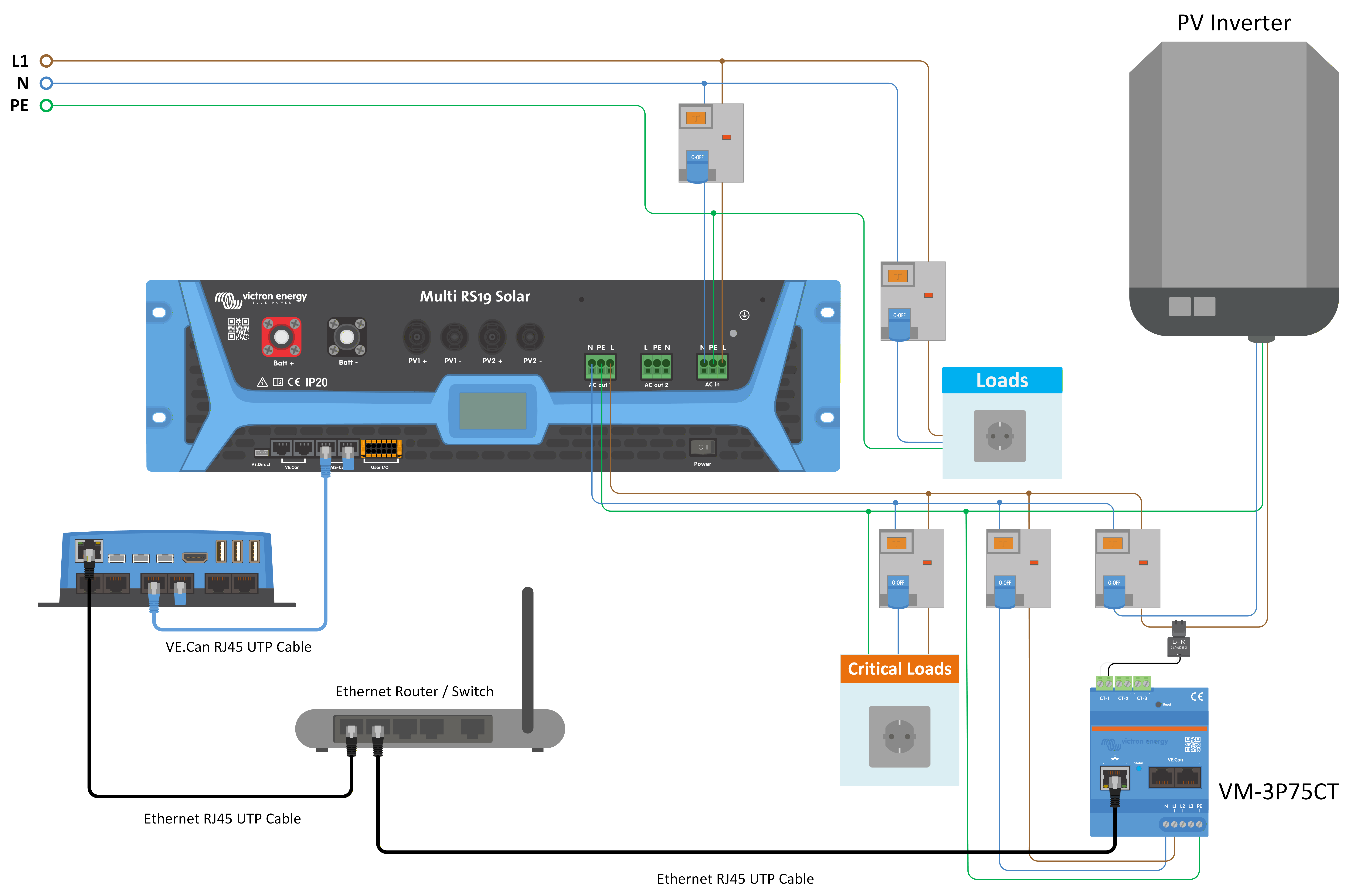
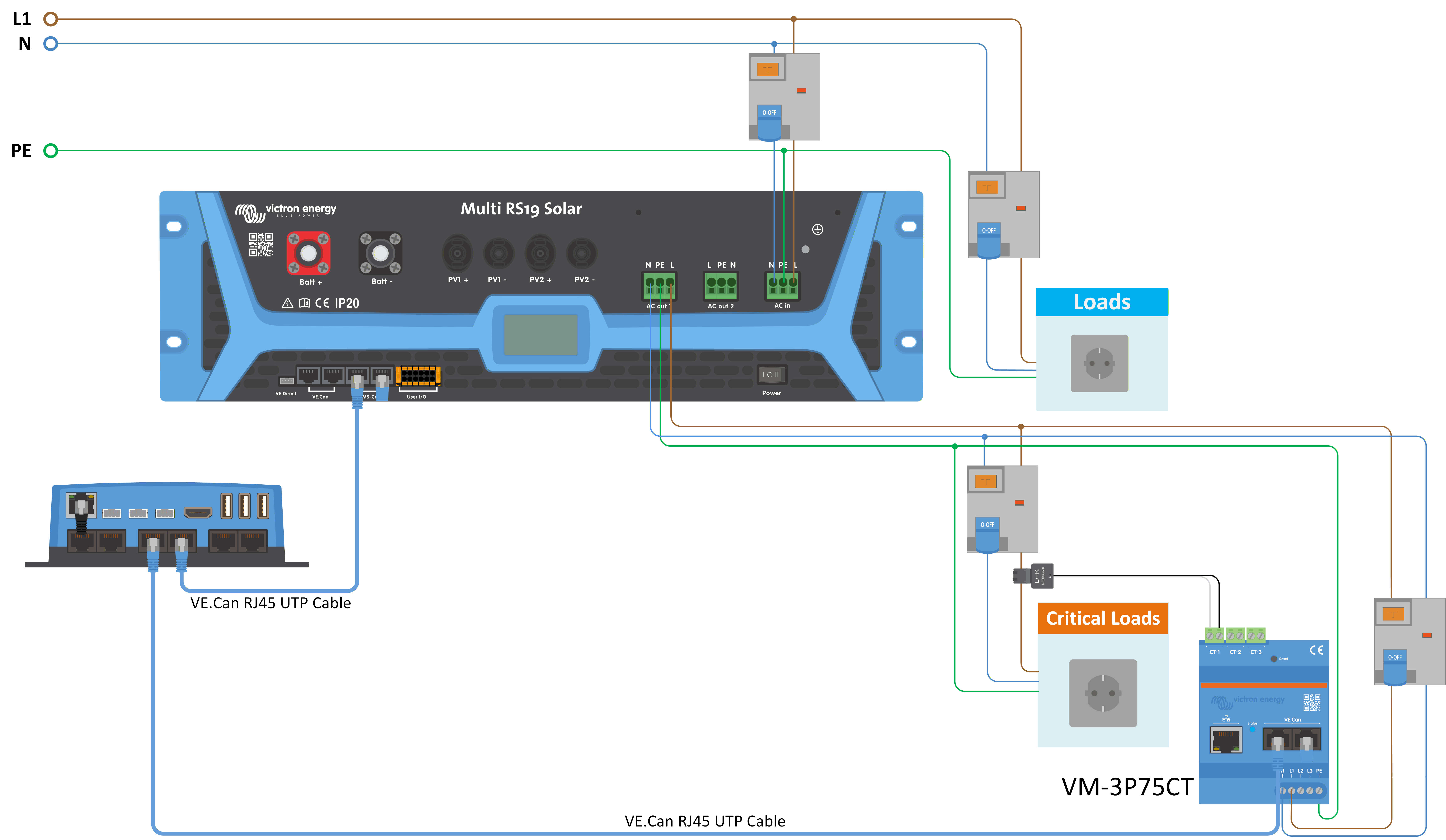
The Victron energy meter can be connected using either VE.Can or Ethernet. A GX device is required for Ethernet connectivity. See example diagrams below.
Note
For Ethernet connectivity, the Multi RS19 Solar must have firmware version 1.26 or above installed.
The GX device must be running version 3.70 or above.
Warning
Any Wi-Fi network segments between the energy meter and the GX device should be avoided due to latency issues.
Use wired Ethernet connections between the energy meter, router/switch, and GX device.
See the VM-3P75CT manual for full details.
The energy meter can be configured for single phase or three phase systems.
Once the role is selected in the energy meter settings, then energy meter support can be set in the Multi RS19 Solar settings:
|
|
|
|
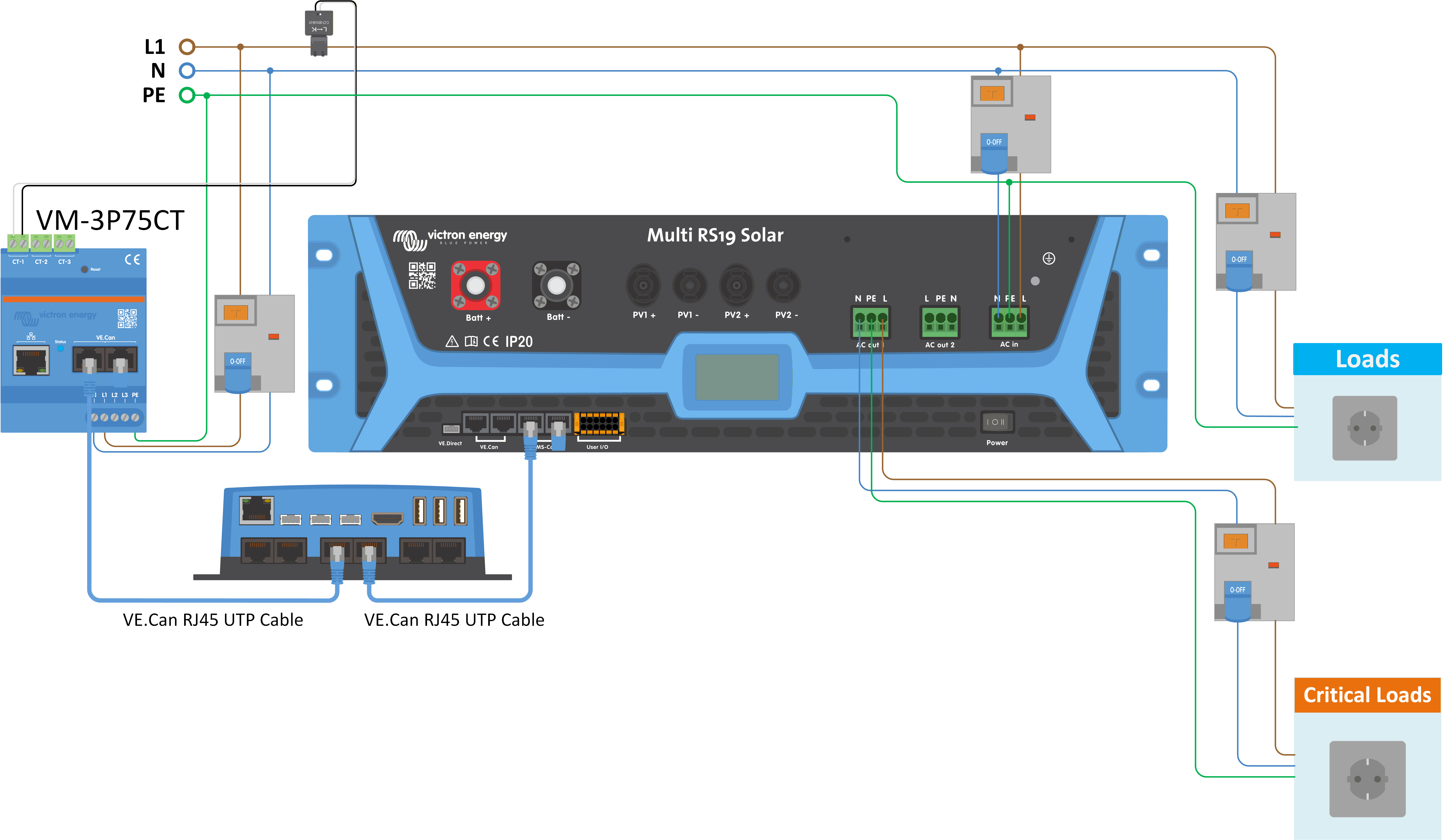
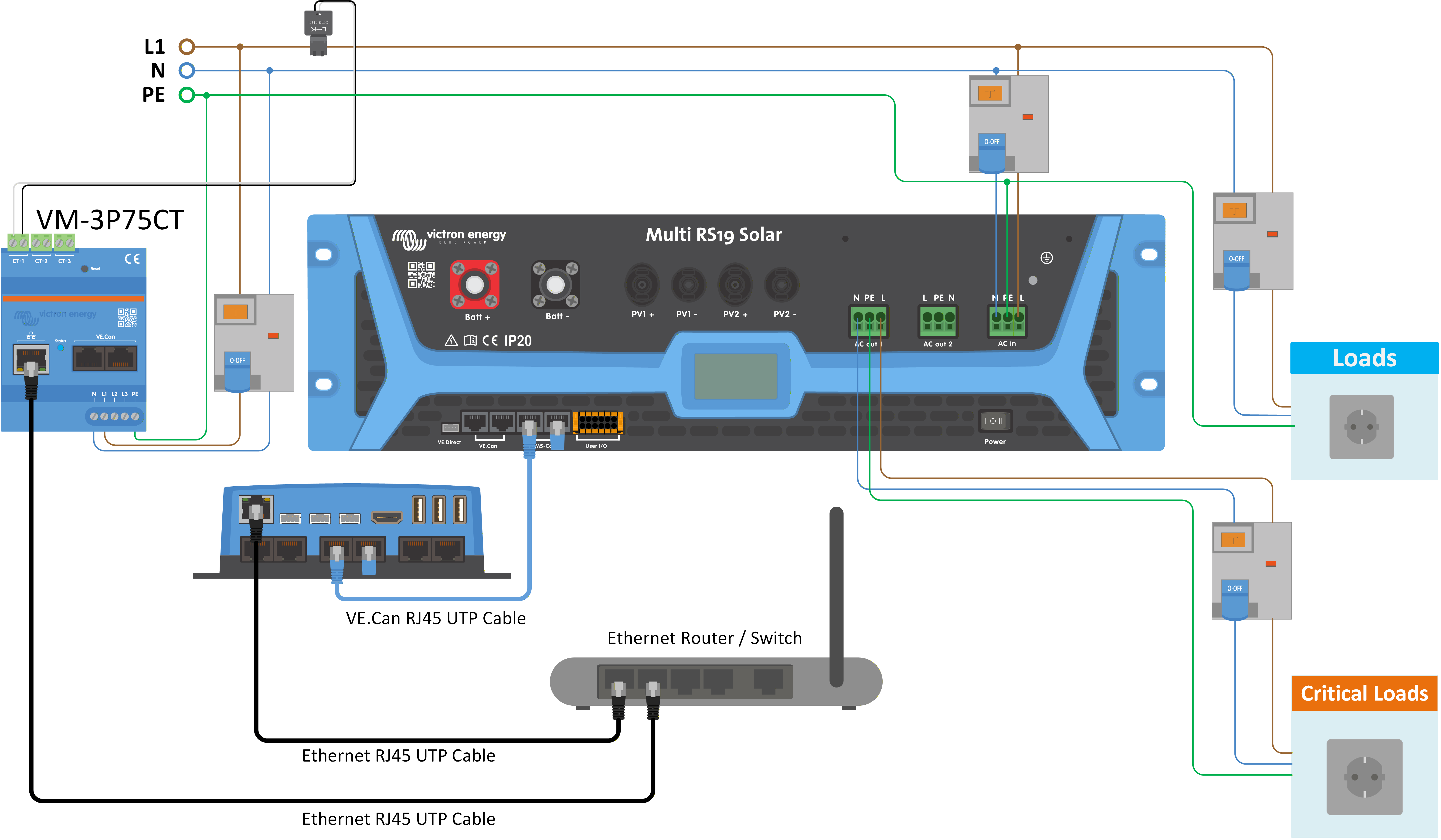
The above wiring example can be used when the energy meter role is set up as "Grid meter" or "Generator". The incoming current from the AC grid or a generator is measured before the AC input of the Multi RS19 Solar. or any non-critical AC loads.
If "Energy meter support" is enabled, a current limit can be set at the energy meter to prevent excessive load on a weak AC grid. If the non-critical loads exceed the current limit at the energy meter then the Multi RS19 Solar will begin to "power assist" to try and maintain the current limit at or below the set point.
|
|
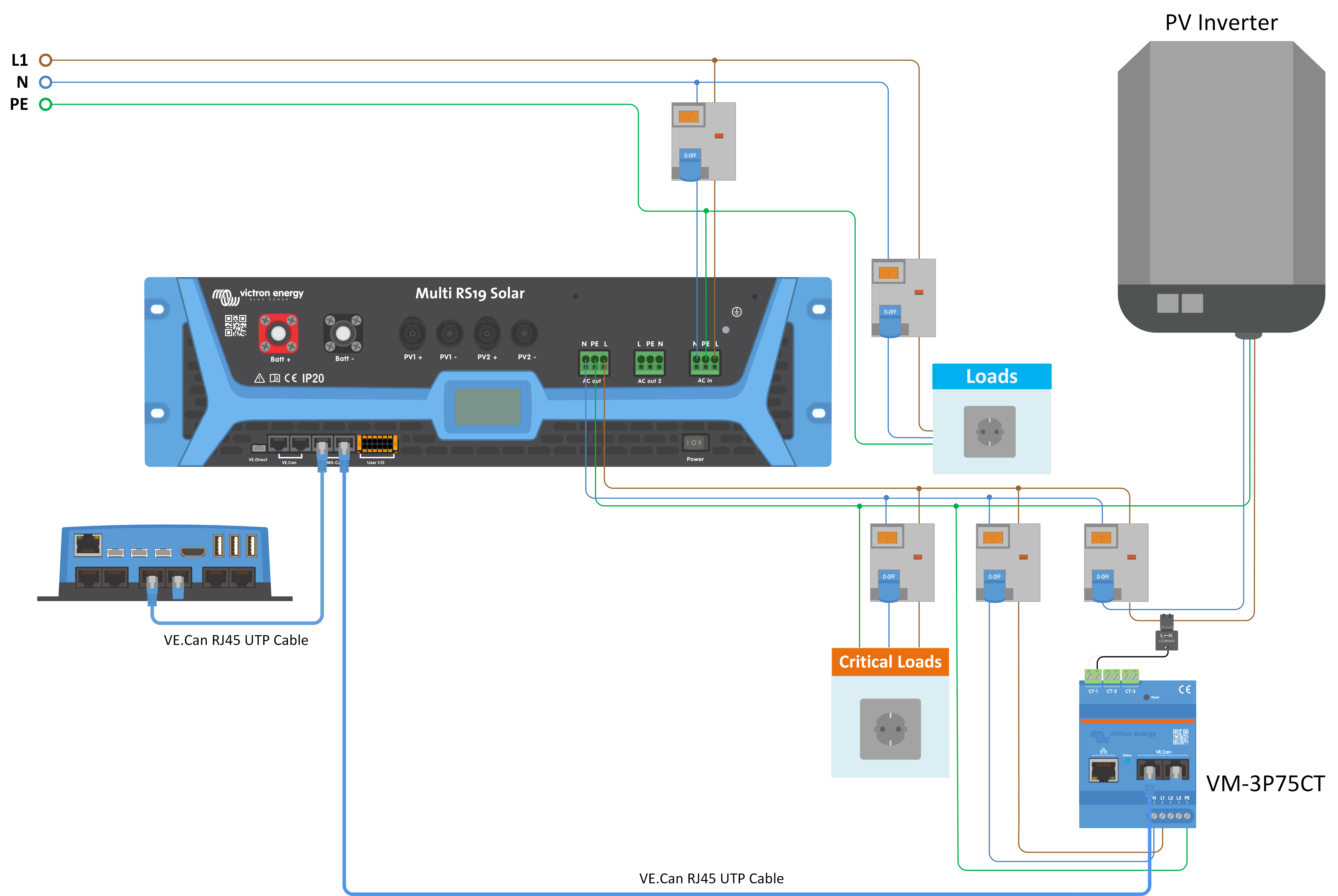
If a generic PV inverter is connected to the AC output of the Multi RS19 Solar the energy meter role should be set to "PV Inverter" and wired to measure the current produced by the PV inverter.
|
|
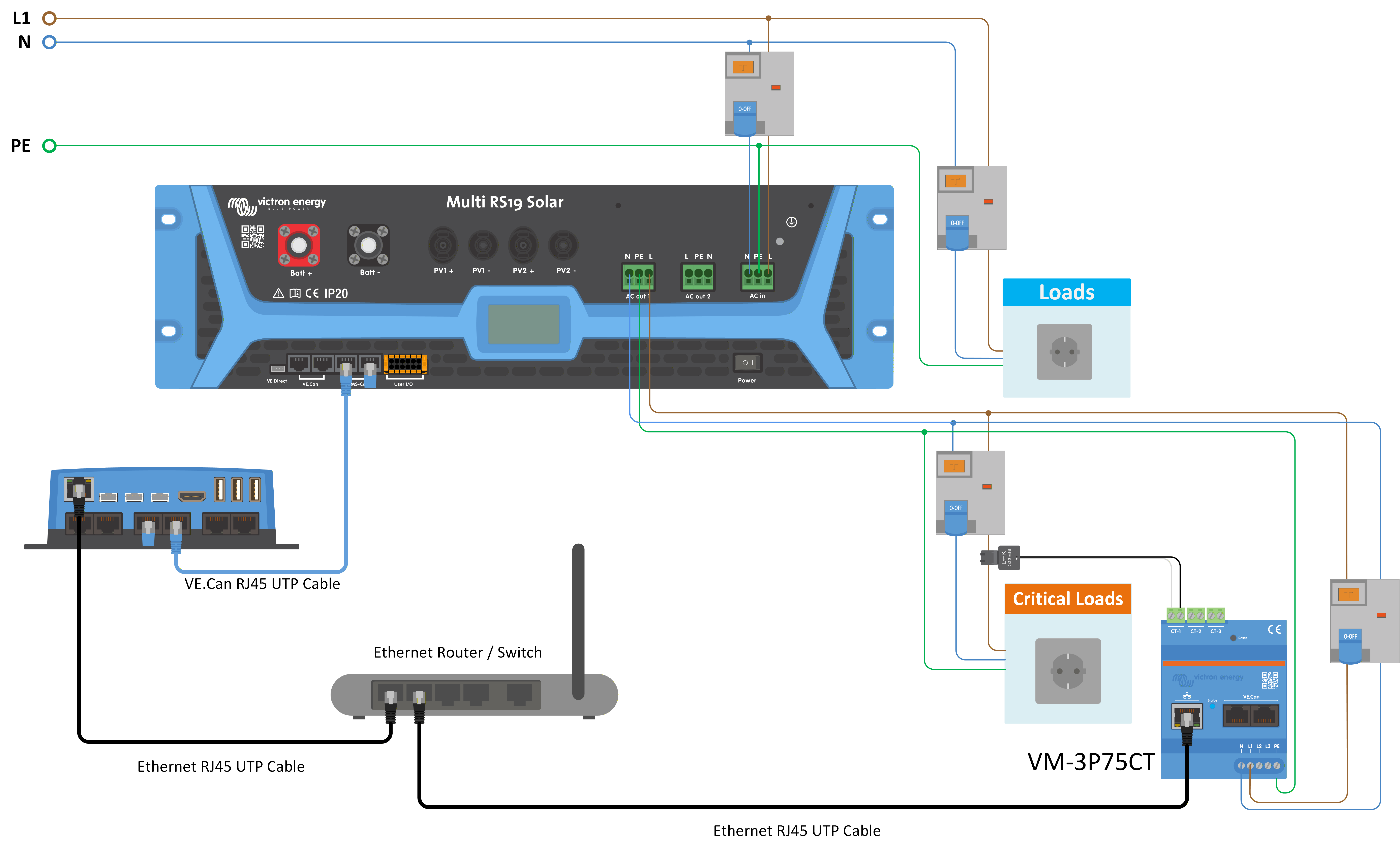
When the energy meter role is set to "AC load" then the energy meter can be wired to measure specific loads. For example, a water heater circuit could be measured to monitor its power consumption and also track the amount of energy it uses.
3.18. Large systems - 3 phase
Warning
3 phase systems are complex. We do not support or recommend that untrained and/or inexperienced installers work on these size systems.
If you are new to Victron, please start with small system designs, so that you become familiar with the necessary training, equipment and software required.
It is also recommended to hire an installer that has experience with these more complex Victron systems, for both the design and the commissioning.
Victron is able to provide specific training for these systems to distributors via their regional sales manager.
Note
VE.Can 3 phase networking differs from VE.Bus. Please read the documentation in full, even if you have experience with large VE.Bus systems.
Mixing different models of Inverter RS (ie. the model with Solar and without Solar) is possible. However mixing Inverter RS with Multi RS is not currently supported.
DC and AC wiring
Each unit needs to be fused individually on the AC and DC side. Make sure to use the same type of fuse on each unit.
The complete system must be wired to a single battery bank. We do not currently support multiple different battery banks for one connected 3 phase system.
Communication wiring
All units must be daisy chained with a VE.Can cable (RJ45 cat5, cat5e, or cat6). The sequence for this is not important.
Terminators must be used at either ends of the VE.Can network.
The temperature sensor can be wired to any unit in the system. For a large battery bank it is possible to wire multiple temperature sensors. The system will use the one with the highest temperature to determine the temperature compensation.
Programming
All settings need to be set manually by changing the settings in each device, one by one. For now synchronising settings to all devices is not supported by VictronConnect.
There is a partial exception to this - changing the AC output voltage will temporarily be pushed to other synchronised devices (to prevent undesired power flow imbalance via the AC output). However this is not a permanent settings change and still needs to be manually set on all devices if you wish to change the AC output voltage.
Charger settings (voltage and current limits) are overridden if DVCC is configured and if a BMS connected via the BMS-Can port is active in the system.
System Monitoring
It is strongly recommended that a GX Family Product is used in conjunction with these larger systems. They provide highly valuable information on the history and performance of the system.
System notifications are clearly presented and many additional functions are enabled. Data from VRM will greatly speed support if it is required.
3.19. 3 phase installation
The Multi RS19 Solar supports single phase, and three phase configurations. It does not currently support split phase.
The factory default is for stand alone, single unit operation.
If you wish to program for three phase operation, it requires 3 units.
The maximum supported system size is 3 units in total, with a single unit on each phase.
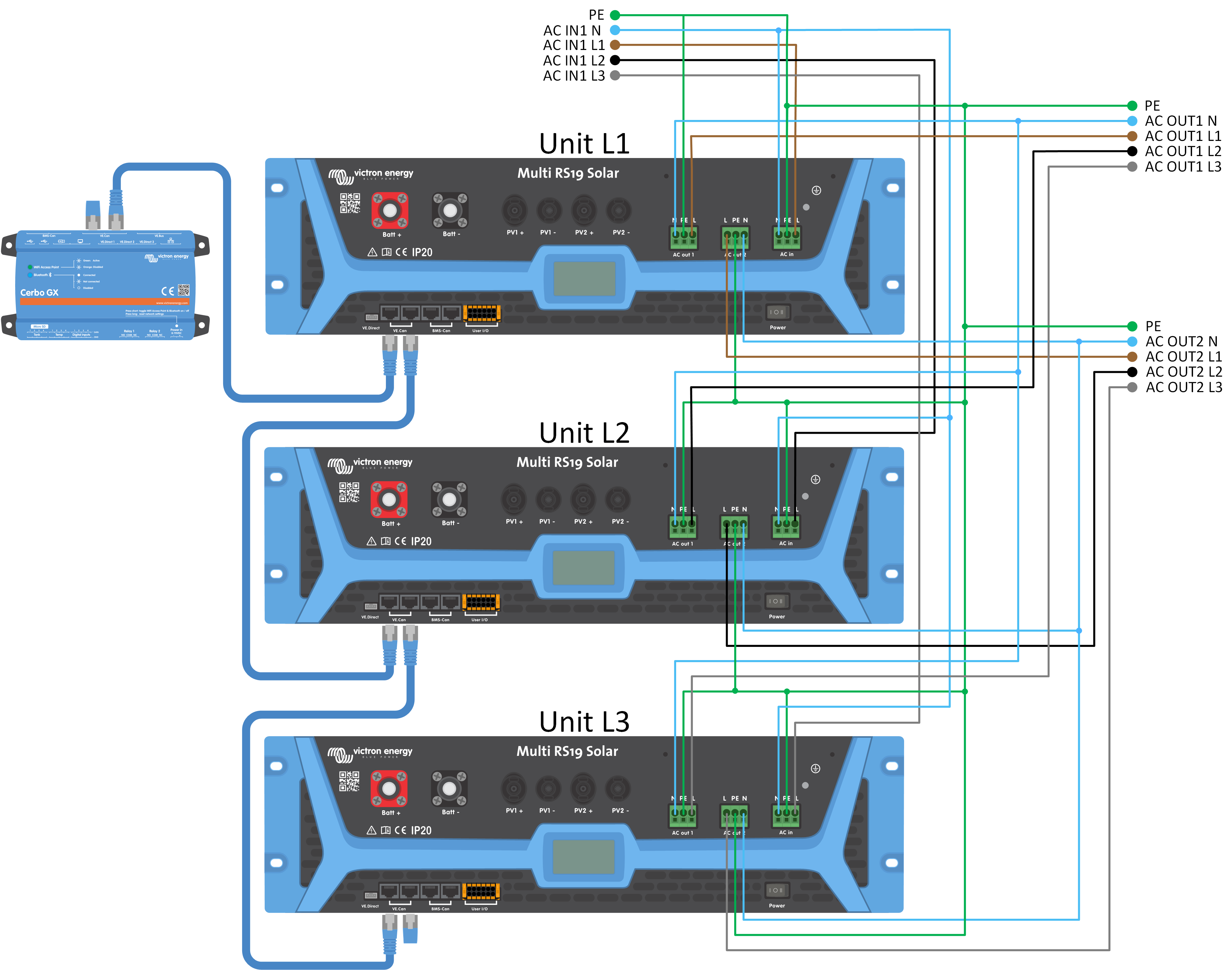
All Multi RS19 Solar units must be connected to each other via VE.Can connections, with a VE.Can terminator at the start and the end of the bus.
Once the units are connected to the battery and via VE.Can they will need to be configured.
Delta configurations not supported
For units in 3 phase configuration: Our products have been designed for a star (Y) type three phase configuration.
In a star configuration all neutrals are connected to a so called: “distributed neutral”.
We do not support a delta (Δ) configuration. A delta configuration does not have a distributed neutral and will lead to certain inverter features not operating as expected.
3.20. 3 phase programming
In order to configure a 3 phase system the Multi RS19 Solar will need to be correctly installed, and running firmware version v1.13 or later.
Configuring a system for three phase or single phase is done in VictronConnect in the System menu.
Caution
AC output power will be disconnected for a few seconds when switching System configuration modes. Make sure the system is configured BEFORE connecting the inverter AC outputs to the load.
Note
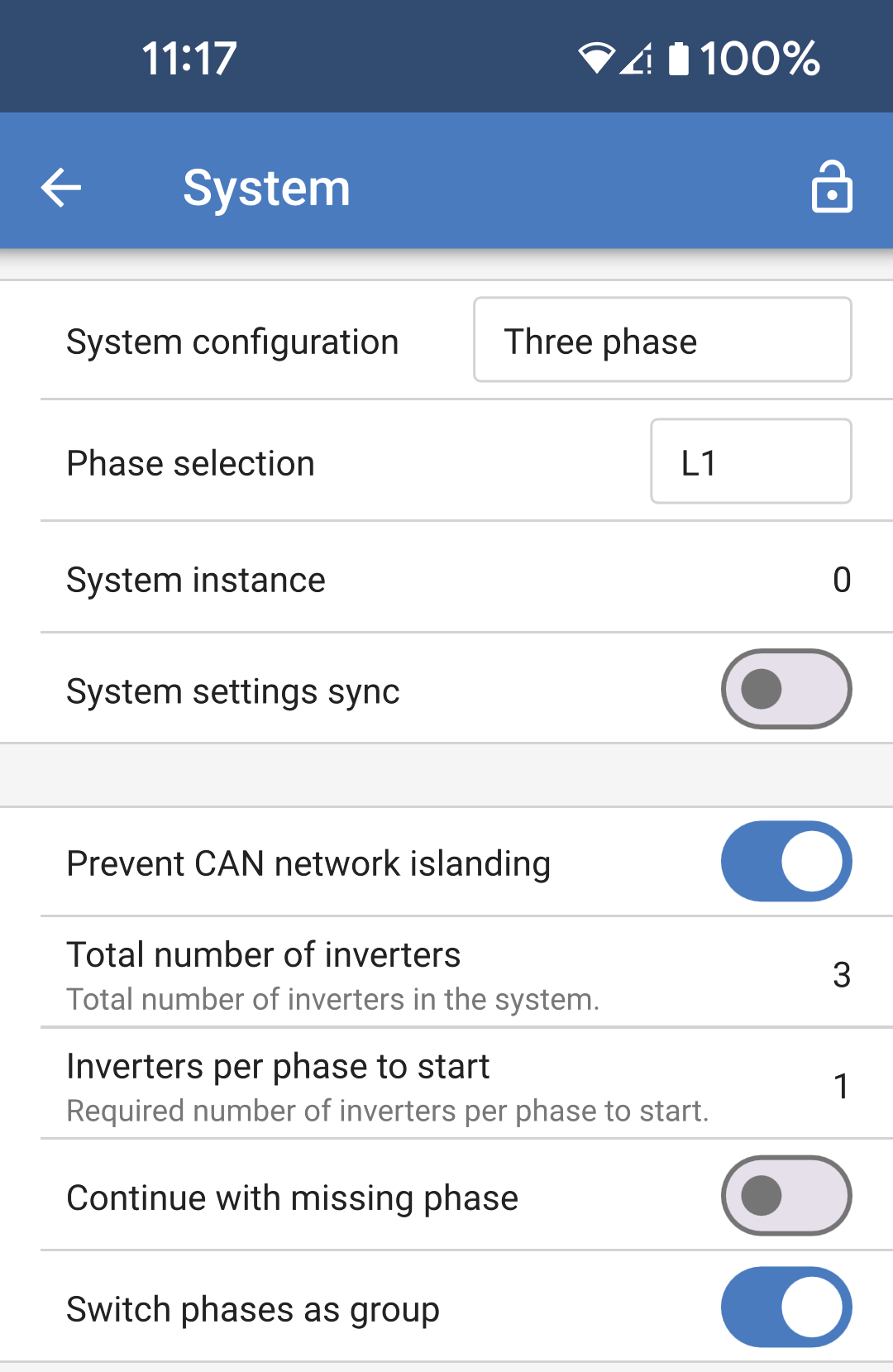
These System settings must be programmed individually, and set correctly on all connected units for synchronised operation.
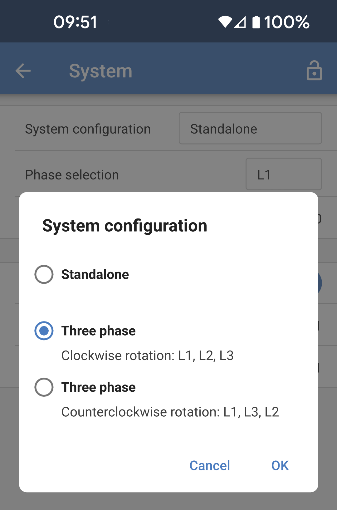
System configuration: The factory default System configuration setting is "Standalone". Tap the box to bring up a popup menu where you can select "Three phase". There are two three phase options to choose from, either clockwise or counter clockwise, depending upon the phase rotation at the installation site. You'll need to apply these same settings to each unit individually. |
|
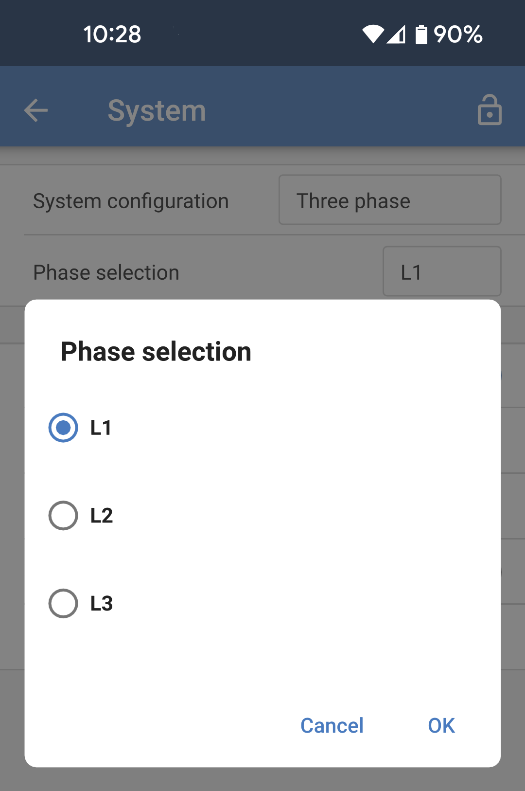
Phase selection: Select the correct phase that each particular unit is connected to. There can only be one unit per phase. Do this for each individual unit. It is also advisable to physically label each unit and also give a matching custom name in the product info settings. |
|
|
|
Note on redundancy and continuous output during firmware updates
A three phase system can be firmware updated without losing power on the AC output.
Make sure that there is stable AC input available when starting the update and the unit currently being updated will switch to AC-passthrough mode.
The AC synchronisation mechanism used for 3 phase has a 'protocol' version embedded.
Units can work together even with different firmware versions, as long as they are running the same protocol version.
This allows for continuous uninterrupted supply even when updating firmware, as the units will individually update one at a time, while others continue to synchronise and provide the stable AC output.
If Victron needs to change the 'protocol' version number, it will be clearly noted in the firmware change log. Always read this before updating.
In the event that there are multiple protocol versions running on the same VE.Can bus, all units will indicate error #71 until they are all updated to the same version.
Known Issues
The 'UPS function' is too sensitive in 3 phase operation compared to stand-alone operation. Disable the 'UPS function' in case the Multi disconnects frequently from the AC input.
Charge currents are not yet balanced across the 3-phases when the charger is in voltage-controlled mode.