19. Troubleshooting
19.1. Error Codes
Different origins of errors
The GX device can display its own error codes, as well as those from connected devices.For device-specific codes, refer to:
Multi and Quattro inverter/chargers: VE.Bus Error Codes
MPPT Solar Chargers: MPPT Solar Charger Error Codes
GX Error #42 - Storage corrupt
The internal flash memory is corrupt. This partition stores settings, serial numbers, and Wi-Fi credentials.
Solution: The device must be returned for repair or replacement. This cannot be fixed via firmware or in the field.
GX Error #46 - Data partition full
The alarm triggers when free space on the data partition drops below 10%. A full data partition can cause Venus OS to malfunction and prevent services from starting.
The most common cause is data written by third-party apps such as Node-RED or Signal K. To see which apps are installed, go to Settings → General → Support status.
For solutions, see Venus OS Large - Disk space issues / data partition full
GX Error #47 - Data partition issue
The internal storage is likely damaged, causing the device to lose configuration.
Solution: Contact your dealer or installer. See our Victron Energy Support page.
GX Error #48 - DVCC with incompatible firmware
DVCC is enabled, but not all system components are running compatible firmware.
Solution: Refer to the DVCC chapter of this manual for firmware requirements.
Note for systems with Pylontech and BMZ batteries:
Since Venus OS v2.80, DVCC is enforced for Pylontech and BMZ batteries. Older systems may show this error.
Solution:
Disable automatic updates; Settings → General → Firmware → Online updates → Auto update.
Roll back to v2.73 (see Install a specific firmware version from SD/USB).
And after that, consider having an installer update all device firmware.
Note for systems with BYD, MG Energy Systems and Victron Lynx Ion BMS batteries:
Since Venus OS v2.40, DVCC auto-enables for supported BMS types. Older systems may lack components to support this.
Solution:
Disable automatic updates; Settings → General → Firmware → Online updates → Auto update.
Roll back to v2.33; to roll back to a previous firmware version see Install a specific firmware version from SD/USB.
Ensure DVCC is disabled.
Consult your installer to check if your system uses two-wire control (earlier alternative to DVCC).
If there are no charge/discharge wires between BMS, inverter/chargers, and charge controllers, DVCC is required for the above-mentioned battery brands. This also requires minimum firmware versions on connected devices.
GX Error #49 - Grid meter not found
In ESS setups with External Grid Meter selected, no meter was detected.
Solution: Check system wiring and configuration.
GX Error #51 - mk3 firmware needs update
Update the MK3 controller inside the GX device to enable recent features like generator start/stop warm-up/cooldown.
To update:
Go to Settings → Devices → MultiPlus/Quattro/EasySolar.
A notification there indicating a new MK3 version is available. Tap the notification and start the update
There is a small chance, around 5% based on our data, that this update may briefly restart the system, causing the inverter/charger to cycle off and on.
If no update prompt appears, your system is already up to date. This manual update is only required once and was designed to be user-initiated due to the small restart risk. Future updates will install automatically without causing a restart.
GX Error #60 – Could not connect to the GX device
This error occurs when the Marine MFD app fails to establish a connection with the GX device.
To resolve the issue, try rebooting the GX device and/or the MFD.
19.2. FAQ
19.2.1. Q1: I cannot switch my Multi/Quattro system on or off
To solve the problem, first find out how the system is connected, and then follow the right step by step instruction below. There are two ways to connect a Multi/Quattro system to a Nucleo GX. In most systems they will be connected directly to the VE.Bus port on the back of the NGX. And, option two, in some systems they are connected to the Nucleo GX using a VE.Bus to VE.Can interface.
Step by step instructions when connected to VE.Bus port on the NGX
Update the Nucleo GX to the latest available version.
See our blog posts in the https://www.victronenergy.com/blog/category/firmware-software/.
Do you have a Digital Multi Control or VE.Bus BMS in the system? In that case it is normal that on/off is disabled.
See also the VE.Bus related notes in the NGX manual.
In case you have had a Digital Multi Control or VE.Bus BMS connected to your system, the Nucleo GX remembers it and even when those accessories have been removed, the On/Off switch will still be disabled. To clear the memory, execute a Redetect system in the Remote Console menu for your Multi or Quattro.
For details see the Advanced menu section.
For parallel/three-phase systems consisting of more than 5 units: depending on temperature and other circumstances, it might not be possible to switch a system back on after switching it off with the NGX. As a work around you'll need to unplug the VE.Bus cable from the back of the NGX. And plug it back in after starting the VE.Bus system. The real resolution is to install the “NGX dongle for large VE.Bus systems”, partnumber BPP900300100. For details, read its connection instruction.
Step by step instructions when connected to NGX via VE.Can.
Update the Nucleo GX to the latest available version. See our blog posts in the firmware category.
Update the VE.Bus to VE.Can interface to the latest version. The easiest way to do that is by using Remote firmware update: having a special piece of hardware, the CANUSB, is then not necessary.
Do you have a Digital Multi Control or VE.Bus BMS in the system? In that case it is normal that on/off is disabled. See also the VE.Bus related notes in the NGX manual
In case you have had a Digital Multi Control or VE.Bus BMS connected to your system, and it is now no longer connected, the Canbus interface remembers it. Therefore, even after those accessories have been removed, the On/off switch will still be disabled. Clearing this memory is unfortunately not possible yourself, please contact us so we can help you.
19.2.2. Q2: Do I need a BMV to see proper battery state of charge?
It depends. For details see the Battery state of charge (SoC) chapter.
19.2.3. Q3: I have no internet. Where can I insert a SIM card?
GX devices do not have a built-in 3G or 4G modem, and therefore do not include a SIM card slot.
To connect to the internet via mobile data, purchase a mobile router with Ethernet ports. These devices handle the SIM card and provide an internet connection to the GX device over Ethernet.
19.2.4. Q4: Can I connect both a GX Device and a VGR2/VER to a Multi/Inverter/Quattro?
No, this is not possible.
Instead of this combination, we recommend using a GX device together with a GX LTE 4G or mobile router. See Internet connectivity for more information.
19.2.5. Q5: Can I connect multiple Nucleo GX to a Multi/Inverter/Quattro?
No.
19.2.6. Q6: I see incorrect current (amps) or power readings on my NGX
Examples are:
I know that a load is drawing 40W from the Multi, but the NGX shows 10W or even 0W.
I see that the Multi is supplying a load with 2000W, while in inverter mode, but from the battery only 1850W is being taken. Is those 150W coming out of nowhere?
The general answer is: the Multi and Quattros are not measurement instruments, they are inverter/chargers, and the measurements shown are a best effort delivery.
In more detail, there are several causes for measurement inaccuracies:
Part of the power taken from a battery by the inverter is being lost in the inverter, converted into heat: efficiency losses.
The Multi does not really measure the power being drawn from the battery. It measures the current at the output of the inverter, and then makes an assumption of the power being drawn from the battery.
Watts vs VA: depending on the Multi/Quattro firmware version and also the NGX firmware version, you are either looking at VAs (the result of calculating AC voltage * AC current) or looking at a Watts measurement. To see WATTS on the NGX , update your NGX to the latest version (v1.21 or newer). Also make sure the firmware version in your Multi supports Watts readout, minimum versions are xxxx154, xxxx205 and xxxx300.
Multis/Quattros connected to the NGX via a VE.Bus to VE.Can interface will always reports VAs, not (yet) Watts.
If a current sensor assistant is loaded in a Multi/Quattro and no sensor is connected it will return invalid power / kWh values.
If a current sensor assistant is loaded in a Multi/Quattro make sure the position is set correctly and the scale match with the dipswitches on the sensor itself.
A current sensor assistant measures and reports VAs, not Watts.
Tips to prevent measurement problems
While VEConfigure or VictronConnect is connected via an MK3 interface, both programs periodically send a command that blocks communication to the GX device. During this time, it cannot read any data, including measurements, from the Multi or Quattro. Once VEConfigure or VictronConnect is closed, communication between GX device and the Multi/Quattro is restored.
VE.Bus is not a 100% plug and play system: if you disconnect the NGX from one Multi, and very quickly connect it to another, it can result it wrong values. To make sure that this is not the case, use the 'redetect system' option in the Multi/Quattro menu on the NGX .
19.2.7. Q7: There is a menu entry named "Multi" instead of the VE.Bus product name
A VE.Bus system can be completely turned off, including its communication. If you turn a VE.Bus system off, and thereafter reset the NGX, the NGX cannot obtain the detailed product name and shows “Multi” instead.
To get the proper name again, go into the Multi menu on the NGX and set the Switch menu entry to On or in case a Digital Multi Control is present, set the physical switch to On. Note that when there is a BMS, above procedure only works when within battery working voltages.
19.2.8. Q8: There is a menu entry named "Multi", while there is no Inverter, Multi or Quattro connected
If a NGX ever saw a VE.Bus BMS or Digital Multi Control (DMC), it will remember them, until 'Redetect system' is started from the NGX menu. After a minute, restart the NGX: Settings → General → Reboot.
19.2.9. Q9: When I type the IP address of the Nucleo GX into my browser, I see a web page mentioning Hiawatha?
Our plan is to at least run a website where you can change settings and see the current status. If all works out as we would like to, there might come be a fully functional version of the online VRM Portal running locally on the Nucleo GX. This allows people without an internet connection, or an intermittent internet connection to have the same features and functionality.
19.2.10. Q10: I have multiple Solar chargers MPPT 150/70 running in parallel. From which one will I see the relay status in the NGX menu?
From a random one.
19.2.11. Q11: How long should an automatic update take?
The size of the download typically is around 90MB. After download it will install the files which can take up to 5 minutes.
19.2.12. Q12: I have a VGR with IO Extender, how can I replace this with a Nucleo GX?
It is not yet possible to replace the IO Extender functionality.
19.2.13. Q13: Can I use Remote VEConfigure, as I was doing with the VGR2?
Yes, see VE Power Setup manual
19.2.14. Q14: The Blue Power Panel could be powered through the VE.Net network, can I also do that with a Nucleo GX?
No, a Nucleo GX always needs to be powered itself.
19.2.15. Q15: What type of networking is used by the Nucleo GX (TCP and UDP ports)?
Basics:
The Nucleo GX needs to have a valid IP address including a working DNS server and gateway. By default obtained from a DHCP server. Manual configuration is also possible.
DNS port 53 UDP and TCP
NTP (time sync) UDP port 123. NTP uses a pool of servers provided by ntp.org, so this will connect to a wide variety of servers.
VRM Portal:
Both in 'VRM read-only' mode and 'VRM full' mode, data is transmitted to the VRM Portal using ccgxlogging.victronenergy.com. This address resolves to multiple IP addresses, and posting is done via HTTPS POST and GET requests on port 443. There is an option in the menu to use HTTP instead, port 80. Note that in that case it will still send sensitive data such as related access keys (required for 'VRM full' mode) over HTTPS/443.
Firmware updates:
The NGX connects to https://updates.victronenergy.com/ on port 443.
Remote support and Remote Console on VRM:
An outbound reverse SSH connection is made to relaynearme46.victronenergy.com when either one, or both, of those features are enabled. The supporthosts.victronenergy.com record resolves to multiple IP addresses, and the DNS uses Geo-Location to resolve it to the nearest server. This outbound SSH connection tries multiple ports: port 22, port 80 or port 443. The first that works is used, and in case it loses connection it will retry them all again.
No port forwarding or other internet router configuration is necessary to use these features.
More information about the Remote Support feature is in the next FAQ item.
More information about troubleshooting Remote Console on VRM is in here: Remote Console on VRM - Troubleshooting.
Firewall / IP Address Filtering
If installed in a network environment where strict outgoing IP address filtering is in place, the required addresses to approve can be obtained by resolving the A and AAAA records of the aforementioned DNS names. It depends on the firewall software used whether usage of DNS names in the rule set will resolve to one or multiple addresses, or whether it will continiously re-resolve to detect changes. It is likely neither of those are true, so custom monitoring or tooling is required.
Also note that the DNS names used are subject to change in future Venus versions.
Two-way communication (Remote VEConfig and Remote Firmware updates):
Connects to mqtt-rpc.victronenergy.com on port 443; and also connects to the mqtt{1 to 128}.victronenergy.com server farm.
MQTT on LAN:
When enabled, a local MQTT broker is started, which accepts TCP connections on port 8883 (SSL) and 1883 (Plain text).
Depending on, the NGX will also (try to) connect to the Victron MQTT cloud servers. This connection always uses SSL and port 8883.
Remote Console on LAN:
Remote Console on LAN requires port 80 (small website hosted the GX device). And also requires port 81, which is the listening port for the websocket tunnel to VNC.
Modbus TCP:
When enabled, the ModbusTCP server listens on the common designated port for Modbus TCP, which is 502.
SSH Root Access:
Port 22 - see the Venus OS root access documentation.
This is a software developers feature.
19.2.16. Q16: What is the functionality behind the menu item Remote support in the General menu?
Enabling remote support grants Victron Engineers access the device for diagnostics and troubleshooting over the reverse SSH tunnel that is maintained when the GX's VRM mode is set to full. If the VRM mode is not set to full, the tunnel will be set up specifically for remote support.
The connection uses ports 80, 22, or 443 to supporthosts.victronenergy.com and works behind most firewalls. Remote support is disabled by default.
19.2.17. Q17: I don’t see support for VE.Net products in the list, is that still coming?
No.
19.2.18. Q18: What is the data usage of the Nucleo GX?
Data usage varies greatly depending on the number of connected products, system behaviour, logging interval, VRM access mode, and features like Remote Support or update checks.
If you’re on a limited data plan, monitor usage during normal operation. Most routers offer built-in traffic counters; advanced tools like Wireshark provide detailed tracking.
19.2.19. Q19: How many AC Current Sensors can I connect in one VE.Bus system?
The current maximum is 9 sensors (since Nucleo GX v1.31). Note that each need to be configured separately with an assistant in the Multi or Quattro to which it is wired.
19.2.20. Q20: Issues with Multi not starting when NGX is connected / Caution when powering the NGX from the AC-out terminal of a VE.Bus Inverter, Multi or Quattro
Ensure that both the GX device and the MultiPlus are running the latest firmware.
If the GX device is powered via an AC adaptor connected to the AC-out of a VE.Bus Inverter, Multi or Quattro, a deadlock can occur after the VE.Bus device is powered down, for example, during a black start or fault. In this state, the VE.Bus product will not start until the GX device is powered, but the GX device cannot start without power either.
How to resolve the deadlock
Unplug the VE.Bus cable from the GX device briefly. The VE.Bus device will immediately begin to boot.
How to avoid the deadlock
There are two options:
Power the GX device directly from the battery
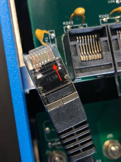
Remove pin 7 in the VE.Bus cable connected to the GX device. Removing pin 7 allows the VE.Bus device to start independently of the GX device.
The fastest and easiest way to remove this pin is with a very thin flat head screwdriver. This can be inserted into the pin grove, and then used to leverage out the gold contact plate. Be aware that this small highly conductive plate will fall out, so this should not be done over the open unit.
Important
When using a Redflow ZBM2/ZCell battery, pin 7 should be removed even if the GX device is DC powered, to prevent deadlocks when the battery cluster reaches 0% SoC.
 |
Consideration when removing pin 7
Removing pin 7 disables the ability of the GX device to fully switch off the VE.Bus device. The unit will stop charging and inverting, but will remain in standby, drawing more power than if pin 7 were intact. This is primarily relevant in marine and automotive systems, where devices are routinely switched off. In such cases, do not remove pin 7, and instead power the GX device from the battery directly.
19.2.21. Q21: I love Linux, programming, Victron and the NGX. Can I do more?
Yes you can! We intend to release almost all code as open source, but we are not that far yet. What we can offer today is that many parts of the software are in script or other non-precompiled languages, such as Python and QML, and therefore available on your Nucleo GX and easy to change. Root password and more information is available here.
19.2.22. Q23: Multi restarts all the time (after every 10sec)
Please check the remote switch connection on the Multi control PCB. There should be a wire bridge between the left and middle terminal. The NGX switches a line which enables the power of the Multi control board. After 10 seconds this line is released and the Multi should take over from there. When the remote switch connection is not wired, the Multi is unable to take over it's own supply. The NGX will retry, the Multi will boot and after 10 seconds stop, and so on.
19.2.23. Q24: What is Error #42?
Error #42 – Hardware fault indicates corrupt flash storage on the GX device. This prevents settings from being saved. After a reboot, all settings revert to defaults, and may lead to further issues.
⚠️ This fault is not field-repairable and cannot be fixed by service departments. Please contact your dealer to arrange a replacement.
Note: Firmware versions prior to v2.30 did not report this error. Since v2.30, Error #42 is visible both on the device GUI and in the VRM Portal.
19.2.24. Q25: My GX device reboots itself. What is causing this behavior?
There are several reasons why a GX device may reboot itself.
One of the most common causes is loss of communication with the VRM online portal.
However, this is only true if the "Reboot device when no contact" option (disabled by default) has been enabled in the VRM online portal settings. If there is no contact with the VRM portal for the time period set in 'No contact reset delay', the GX device will automatically reboot. This process is repeated until communication with the VRM portal is restored. See also chapter Datalogging to VRM - Network watchdog: auto-reboot.
Check the network connection between your GX device and the router. See Troubleshooting data logging.
Preferably use an ethernet connection between your GX device and the router.
Tethered or hotspot connections, e.g. with a cell phone, are not reliable and are often interrupted or do not automatically restore the connection once it has been lost. Therefore, this is not recommended.
Other common reasons that cause the GX device to automatically restart are:
System overload (either CPU, memory, or both).
To reliably detect an overload of the system, there is the D-Bus round trip time (RTT) parameter, and this parameter is available on the VRM Portal. See image below how to set this up on VRM.
An RTT value between 1 and 100ms is fine, although 100ms is already quite high.
RTT peaks occurring now and then are not a problem. Permanently over 100ms is a problem and requires further investigation.
In case the cause is a system overload, then there are two solutions:
Disconnect devices to reduce the load, with associated disadvantages.
Or change the GX device for a more powerful one. In the current product offering - see our Victron GX product range -, the Cerbo GX & Cerbo-S GX, Nucleo GX, and Ekrano GX are (far) more powerful than the Venus GX.
Note
An occasional reboot is not causing any harm to system longevity or performance. The main effect is (temporary) disturbance of the monitoring.
How to create a custom widget in the VRM portal to read out D-Bus round trip time:
Connect to the VRM Portal using a browser.
Click on the Advanced tab in the menu on the left side.
Click on the widget icon in the top right corner.
Scroll down to Custom Widget and click on it to create a new custom widget.
Give it a proper name, chose "Gateway" from the list in Select device and "D-Bus round trip time" in Select parameter.
After clicking on the Save button, the new widget will appear under the Advanced tab.
Tip: Keep the time period to be examined as small as possible to achieve a high resolution of the round trip time.

19.2.25. GPL Note
The software included in this product contains copyrighted software that is licensed under the GPL. You may obtain the Corresponding Source code from us for a period of three years after our last shipment of this product.