5. Connecting Victron products
5.1. AC load monitoring
 |  |  |
All supported energy meter types can be assigned the role of AC meter.
To do this, go to: Settings → →Integrations Energy meters via RS485 → [your_energy_meter] → Role and select AC meter as the role (alternatives include Grid, PV Inverter, and Generator).
Note
Please note that such metered loads are not used in any calculations, just monitoring.
5.2. Battery monitors, MPPTs, Orion XS and Smart IP43 Chargers with a VE.Direct port
Devices with a VE.Direct port, such as BMV battery monitors, MPPT solar chargers, Orion XS, and Smart IP43 Chargers, can be directly connected to a GX device via VE.Direct.
There are two VE.Direct cable types available:
Straight VE.Direct cables - Part no. ASS030530xxx
Right-angle VE.Direct cables - Part no. ASS030531xxx, designed to minimise depth behind mounting panels
Note
VE.Direct cables have a maximum length of 10 m and cannot be extended. For longer distances, use a VE.Direct to USB interface with an active USB extension cable.
VE.Direct to VE.Can interface (limited use)
The VE.Direct to VE.Can interface can be used only with:
BMV-700
BMV-702
 Not compatible with:
BMV-712
MPPT solar chargers
VE.Direct inverters
This interface does not convert data for those devices into CAN-bus messages.
If using the VE.Direct to VE.Can interface:
Ensure the VE.Can network is terminated and powered.
Refer to Q17 in the Victron Data Communication Whitepaper for powering instructions.
Note
This interface is deprecated and not recommended for new installations.
Connecting more VE.Direct devices to your Nucleo GX than physical VE.Direct Ports
If you need to connect more VE.Direct devices than there are VE.Direct ports, the following options are available:
Use the VE.Direct to USB interface.
Use a USB hub if more ports are required.
Please refer to the Overview of connections section for details on the maximum number of VE.Direct devices that can be connected.
Notes on older VE.Direct MPPTs
Some older models, like the MPPT 70/15, are not compatible with GX devices unless they meet a minimum hardware revision:
The device must be from year/week 1308 or later.
Firmware updates will not resolve incompatibility with earlier models.
To identify your model:
Check the serial number printed on the rear label.
Example: HQ1309DER4F means 2013, week 09, which is compatible.
5.2.1. DC load monitor mode
You can use a SmartShunt or BMV-712 to monitor individual DC circuits rather than the entire battery system. To do this, change the Monitor mode setting from Battery Monitor to DC Energy Meter using VictronConnect.
Available DC meter types
Once DC Energy Meter mode is selected, the following types can be assigned in VictronConnect:
Sources: Solar charger, Wind charger, Shaft generator, Alternator, Fuel cell, Water generator, DC-DC charger, AC charger, Generic source
Loads: Generic load, Electric drive, Fridge, Water pump, Bilge pump, DC system, Inverter, Water heater
Integration with GX devices
When connected to the Nucleo GX, the selected meter type along with current (A) and power (W) is displayed in the user interface and sent to the VRM Portal for remote monitoring.
Special case: Type "DC System"
When configured as type “DC System”, the NGX offers extended functionality beyond data logging:
The DC System power display aggregates readings from all SmartShunts configured with the DC System type. This supports multi-location systems, for example, DC systems in both hulls of a catamaran.
DVCC Charge Current Limiting is dynamically adjusted: The GX device compensates for DC loads when setting charge current limits for Multis, Quattros, and Solar Chargers. For example:
If a DC load of 50 A is being measured
And the battery reports a CCL (Charge Current Limit) of 25 A
Then the system sets a limit of 75 A to the charging sources → Resulting in optimised charging behaviour for Yachts, RVs, Coaches, and other systems with significant DC loads.
Notes and limitations:
This feature is supported only by SmartShunt and BMV-712. It is not available on BMV-700 or BMV-702.
The Monitor mode must be configured using VictronConnect directly on the SmartShunt or BMV-712. For setup instructions, refer to the BMV-712 or SmartShunt product manual on the Battery Monitor product page
The NMEA2000-out feature does not support the DC meter types. For example, if a SmartShunt is configured to monitor an alternator, that data will not be available via NMEA 2000.
5.3. VE.Can Devices
To connect a product with a VE.Can port, use a standard RJ45 UTP cable (available with straight and elbow connectors).
Important:
Terminate the VE.Can network at both ends using VE.Can terminator. A bag with two terminators is included with each VE.Can product. Additional terminators are available separately.
Compatibility notes
The MPPT 150/70 must be running firmware v2.00 or newer to function with GX devices
A Skylla-i control panel and an Ion Control panel can be used together with GX devices
All VE.Can devices provide power to the VE.Can network, so no separate VE.Can power supply is required
Protocol converters (e.g. VE.Bus to VE.Can interface, BMV to VE.Can interface) do not power the VE.Can network
VictronConnect-Remote (VC-R) support
The following VE.Can products support VictronConnect-Remote (VC-R), enabling configuration and monitoring via VRM. For more details, refer to the VictronConnect manual.
VE.Can product | VC-R | Remarks |
|---|---|---|
Lynx Shunt VE.Can | Yes | - |
Lynx Smart BMS, Lynx BMS NG | Yes | - |
Inverter RS, Multi RS and MPPT RS | Yes | They also have VE.Direct but must be connected via VE.Can for VC-R |
Blue/Smart Solar VE.Can MPPTs [1] | Yes | Tr and MC4 models |
Skylla-i and Skylla-IP44/-IP65 | Yes | Requires firmware v1.11 |
[1] All VE.Can solar chargers except the very old (big rectangular case with display) BlueSolar MPPT VE.Can 150/70 and 150/85 | ||
5.4. VE.Can Interfaces
The Nucleo GX has two fully functional VE.Can ports. They are independent from a data and connected device perspective. One is labelled VE.Can 1 and is galvanically isolated, the other is labelled VE.Can 2 and is non-isolated.
2 × Fully configurable VE.Can ports (VE.Can 1 is isolated)
Both ports can be set to:
VE.Can (250 kbit/s, default)
BMS-Can (500 kbit/s)
CAN-bus BMS (250 kbit/s)
Other supported CAN profiles such as RV-C
Usage guideline
VE.Can (250 kbit/s, default)
For Victron devices like:
VE.Can MPPTs
Skylla-IP65
Lynx Shunt VE.Can
Lynx Smart BMS and Lynx Smart BMS NG
Terminate both ends using the included VE.Can terminators
BMS-Can (500 kbit/s)
For managed lithium batteries (e.g. BYD, Pylontech, Freedomwon)
Terminate at the GX device with the included terminator
Follow the battery manufacturer’s instructions for termination on the battery side
Important
VE.Can and BMS-Can must not share the same bus
If both are needed, use a GX device with two separate CAN buses (e.g. Cerbo GX MK2 or Ekrano GX)
Port configuration
Access via Remote Console:
Settings → Connectivity → VE.Can port 1 / 2 → CAN-bus Profile
Default settings:
VE.Can: 250 kbit/s
Notes
Some BMS units use CANbus BMS profile at (250 kbit/s). Connect these to a VE.Can port and set the appropriate profile VE.Can & CAN-bus BMS (250 kbit/s).
Only use batteries listed on Victron’s compatibility list to ensure proper communication. Others are not supported.
5.5. Inverter RS, Multi RS and MPPT RS
The Inverter RS, Inverter RS Solar, and Multi RS are equipped with both VE.Direct and VE.Can interfaces. However, for these products:
A GX device must be connected via VE.Can.
VE.Direct cannot be used to connect these devices to a GX system.
The VE.Direct interface on these models is intended solely for programming, using a VE.Direct to USB adapter.
Exception: MPPT RS
The MPPT RS can be connected to a GX device via either VE.Direct or VE.Can, depending on system requirements and available ports.
5.6. BMV-600 series
Connect the BMV-600 using the VE.Direct to BMV-60xS cable. (ASS0305322xx).
5.7. DC Link Box
Connect the DC Link Box with the supplied RJ12 cable. Then connect the BMV-700 to the NGX.
5.8. VE.Can Resistive Tank Sender Adapter
See the VE.Can resistive tank sender adapter manual for details about the adapter.
Connection guidelines
Use a standard RJ45 UTP cable to connect the adapter to a VE.Can network.
Terminate the VE.Can network at both ends using VE.Can terminators.
A bag with two terminators is included with each VE.Can product.
Additional terminators are available separately (Part No. ASS030700000).
Ensure that the CAN-bus is powered.
Refer to the Power chapter in the Tank Sender Adapter manual for details.
5.9. Connecting a GX Tank 140
The GX Tank 140 is an accessory for the Victron GX range of system monitoring products. It supports up to four tank-level sensors, with readings visible locally on the GX device and remotely via the VRM Portal.
Input compatibility The GX Tank 140 supports:
Connection and power
Configuration options
For full technical details, refer to the documentation available on the GX Tank 140 product page. | 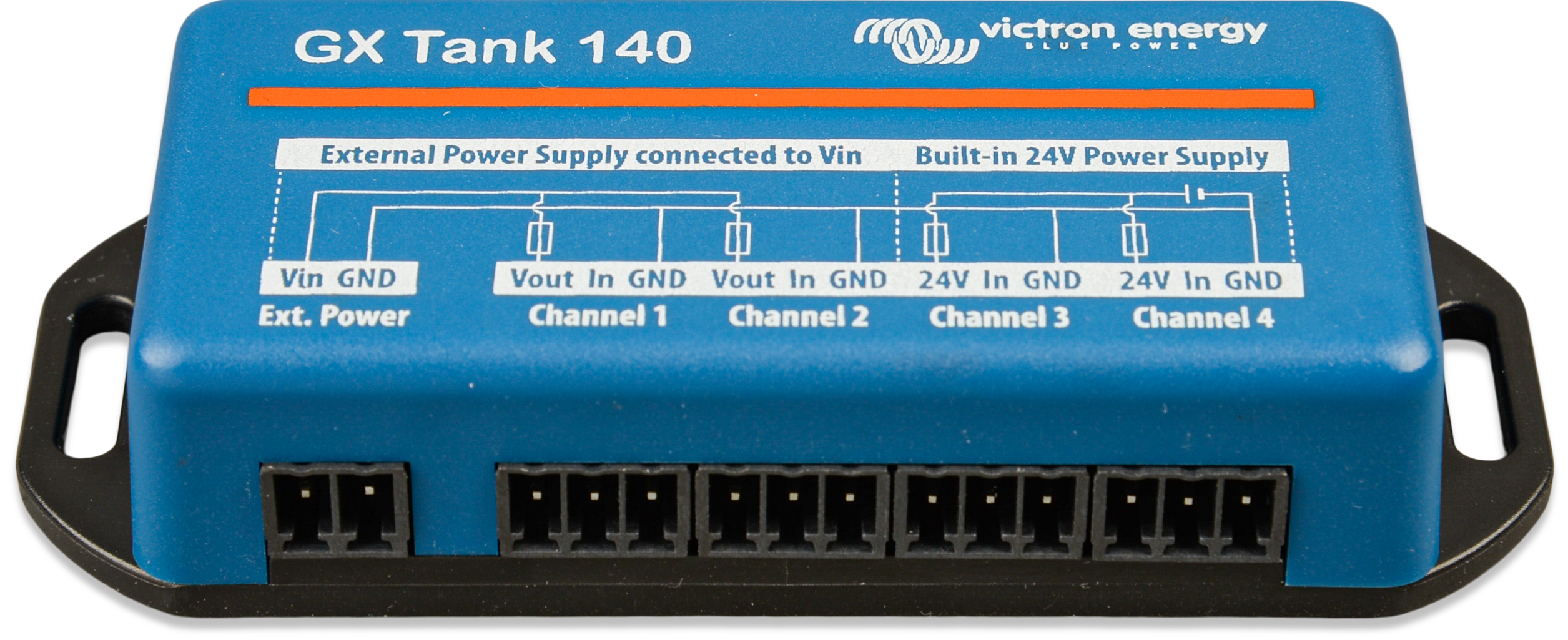  |
5.10. Victron Energy Meter VM-3P75CT
The Victron VM-3P75CT is a versatile energy meter for monitoring single-phase and three-phase power and energy consumption. It can be used to measure:
Grid connection (at the distribution box)
PV inverter output
Generator (AC genset) output
Inverter or inverter/charger output
The meter calculates power values for each phase and transmits the data at a high refresh rate over VE.Can or Ethernet.
Key features
Dual communication options: VE.Can and Ethernet
Compatible with GX devices such as the Cerbo GX and Ekrano GX
Data is viewable on the GX device, VictronConnect, and the VRM Portal
Split-core current transformers for easy, non-intrusive installation
Installation
Follow the setup procedure as described in the VM-3P75CT energy meter manual.
Ensure the energy meter is on the same local network as the GX device when using Ethernet.
VE.Can connection: Plug-and-play. No manual activation required.
Ethernet connection: After initial installation, the energy meter must be activated:
In the GX device menu, go to Settings → Integrations → Modbus Devices → Discovered devices and enable the discovered energy meter; it's disabled by default when first installed and powered. |  |
The VM-3P75CT then becomes visible in the device list and can be monitored from there. For more details, see the energy meter manual. |  |
5.11. EV Charging Station
The EV Charging Station and EV Charging Station NS, with both three-phase and single-phase charging capabilities, integrate seamlessly into the Victron environment via a GX device connection over WiFi. Operation and monitoring are easily managed via Bluetooth using the VictronConnect App.
Set up and configure the EVCS according to the instructions in the EV Charging Station manual. Ensure that:
Communication with the GX device is enabled.
The EVCS and GX device are connected to the same local network.
GX device setup
Note: EV Charging Stations connected before updating the GX device to firmware version 3.12 will be activated automatically. New devices must be enabled manually via the above menu. Once activated, the EVCS will appear in the device list, where it can be monitored and controlled. For further details, refer to the EV Charging Station Manual. Control of the EVCS is also available from the control pane by tapping the control pane button |  |
 | |
 |

5.12. GX IO-Extender 150
The GX IO-Extender 150 is a USB-connected expansion module that extends the available IO ports of GX devices such as the Ekrano GX, Nucleo GX and Cerbo GX.

It bridges the gap between your GX device and the external world, creating endless possibilities for monitoring, control, and automation.
Features
8 digital IOs, configurable as in two sets of four as inputs or outputs (via DIP switch).
4 PWM ports, 0 to 5V with 0,05 V steps for device regulation.
2 latching relays that maintain their state even if the power is lost.
1 solid switch with bat-, load, and bat+ connections for switching requirements.
The plug-and-play USB connectivity makes installation effortless. The GX IO-Extender 150 is simply plugged into an available USB port on the GX device and the inputs/outputs, PWMs and relays immediately become available to the system.
Whether you're managing a complex off-grid solar installation, a marine electrical system, or an industrial backup power solution, the GX IO-Extender 150 expands your ability to deliver on specific requirements:
Monitor additional sensors and equipment
Control external devices with precision
Automate complex system responses
Implement sophisticated control logic
The GX IO-Extender is not intended to be used for general load switching, but rather for signalling. The relays and solid switch have low current ratings that vary based on the voltage being used. Compatible products like those from Energy Solutions (UK), Garmin (USA) and Safiery, and others will be better suited for general switching applications.
Installation
For installation details and technical specifications, refer to the GX IO-Extender 150 manual.
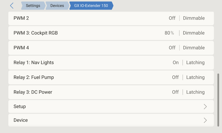
GX device configuration
Once connected and powered, the GX IO-Extender 150 will appear in the Devices list on the GX device. The GX IO-Extender device's page displays:
A dedicated Setup menu allows configuration of each output individually. On each individual output page in the Setup menu, the following options are available:
|  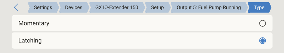 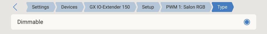 |
Grouping outputs
Each output can be grouped by assigning a group name on the channel’s setup page. Outputs with the same group name are displayed together in a single group card on the Switch pane. This makes it easy to combine related outputs, for example, grouping all lighting outputs under one tile. Channels without a group name will appear in a card labelled with the module name. | 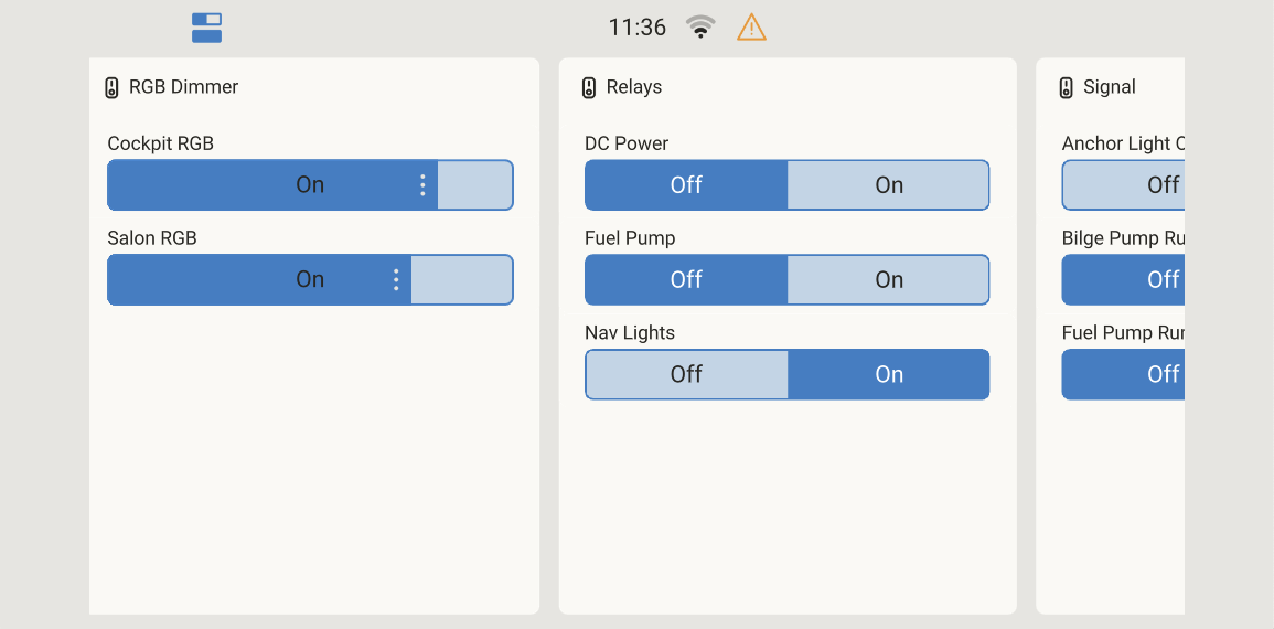 |