21. Appendix
21.1. RV-C
21.1.1. Introduction to RV-C
The GX device offers integration with an RV-C network. The integration is split into two different types:
RV-C out: The GX device transmits data out to the RV-C network, where it can be read by connected displays and control centres. This includes data from Inverter/chargers, Battery chargers, Solar Chargers, batteries and more.
RV-C in: The GX device reads data from the RV-C network for displaying to the user (tank levels) as well as control (Lithionics batteries).
Further details with regards to supported messages (DGNs) for both RV-C out as well as RV-C in, is provided in the following sections.
To enable RV-C, select the RV-C profile for one of the VE.Can ports in the Settings → Connectivity menu.
A detailed specification of the protocol and message definition is publicly available on https://www.rv-c.com.
21.1.2. RV-C out
Generic
The GX main RV-C interface and all virtual devices report the minimum required DGNs:
DGN | DGN# | Description |
|---|---|---|
PRODUCT_ID | 0xFEEB | Manufacturer, product name, serial number |
SOFTWARE_ID | 0xFEDA | Software version |
DM_RV | 0x1FECA | Diagnostics |
DM01* | 0x0FECA | Diagnostics |
* In addition to DGN DM_RV 0x1FECA, also J1939 DGN DM01 0x0FECA is announced for all RV-C out devices to support older RV-C control panels that do not support the DM_RV DGN.
Main interface
The GX main interface identifies as “Control Panel” (DSA=68) on RV-C and is responsible for requesting and processing data from all RV-C nodes.
DC Source messages
All DC connected devices are capable of reporting DC_SOURCE_STATUS_1. This includes the inverter/charger, inverter, charger, battery and solar charger services. VE.Bus Inverter/charger and Battery/BMS reports DC current and voltage, all other devices report voltage only.
According to the RV-C spec, only one node is allowed to broadcast DC source messages from the same instance. Every device type has its own priority which is used to determine which node must send the DC source messages. Consider the following system:
Inverter/charger (DC source instance 1, prio 100)
Solar charger (DC source instance 1, prio 90)
AC charger with 3 outputs (DC source instance 1, 2 & 3, prio 80)
Battery monitor (DC source instance 1, prio 119)
In this case the battery monitor broadcasts DC source data with instance 1, as this has the highest priority. Additionally the AC charger broadcasts DC source data with instance 2 and 3 (output 2 and 3), as there are no other devices with those instances. More information about DC source messages in the RV-C specification manual. Chapter 6.5.1 explains the priority mechanism.
VE.Bus Inverter/charger
Devices
Only VE.Bus MultiPlus/Quattro. Inverter VE.Bus is also exported by this service, but then with the number of AC inputs set to 0. The DSA is set to 66 (Inverter #1).
Instances
Function | Default Instance | Configurable Range |
|---|---|---|
Inverter | 1 | 1..13 |
Charger | 1 | 1..13 |
Line #1 (L1) | 0 | 0..1 |
Line #2 (L2) | 1 | 0..1 |
DC Source | 1 | 1..250 |
Status
DGN | DGN# | Value |
|---|---|---|
INVERTER_AC_STATUS_1 | 0x1FFD7 | L1 AC out voltage, current, frequency L2 AC out voltage, current, frequency L2 data is not sent when not configured |
INVERTER_AC_STATUS_3 | 0x1FFD5 | L1 AC output power L2 AC output power L2 data is not sent when not configured |
INVERTER_STATUS | 0x1FFD4 | Inverter status |
CHARGER_AC_STATUS_1 | 0x1FFCA | L1 AC input voltage, current, frequency L2 AC input voltage, current, frequency L2 data is not sent when not configured |
CHARGER_AC_STATUS_2 | 0x1FFC9 | Input current limit |
CHARGER_AC_STATUS_3C | 0x1FFC8 | L1 AC input power L2 AC input power L2 data is not sent when not configured Power is always positive, also in case of feed-in |
CHARGER_STATUS | 0x1FFC7 | Charger state |
CHARGER_STATUS_2 | 0x1FEA3 | DC voltage, current Charger priority aligns with DC source priority |
CHARGER_CONFIGURATION_STATUS | 0x1FFC6 | Maximum charge current |
CHARGER_CONFIGURATION_STATUS_2 | 0x1FF96 | Input current limit, Maximum charge current (%) |
DC_SOURCE_STATUS_1 | 0x1FFFD | DC voltage, current Fixed priority of 100 (inverter/charger) |
DC_SOURCE_STATUS_2 | 0x1FFFC | Battery temperature Fixed priority of 100 (inverter/charger) |
Commands
DGN | DGN# | Value |
|---|---|---|
INVERTER_COMMAND 1) | 0x1FFD3 | Inverter enable/disable |
CHARGER_COMMAND 1) | 0x1FFC5 | Charger enable/disable |
CHARGER_CONFIGURATION_COMMAND | 0x1FFC4 | Maximum charge current Note: this is a volatile setting and resets to the value the unit was configured with after a restart of the inverter/charger. |
CHARGER_CONFIGURATION_COMMAND_2 | 0x1FF95 | Charger input current limit |
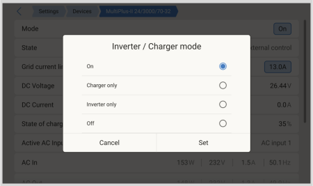
1) From RV-C you can control the charger and inverter part separately. These two on/off values are then combined into a single switch value (as seen on the VE.Bus page in the GX user interface, see top most item in below screenshot). If the inverter/charger is On, switching the charger off will result in Inverter only. Switching the inverter off will result in Charger only (when shore power is connected).
Victron defines the following options to control a combined inverter/charger:
State | Remarks |
|---|---|
Off | Both, inverter and charger are switched off |
Inverter only | Only the inverter is switched on |
Charger only | Only the charger is switched on |
On | Both, inverter and charger are switched on |
This is reflected by the Switch menu option:
Inverter
Devices
Inverter VE.Direct and Inverter RS. The DSA is set to 66 (Inverter #1).
Instances
Function | Default Instance | Configurable Range |
|---|---|---|
Inverter | 2 | 1..13 |
Line (L1) | 0 | 0..1 |
DC Source | 1 | 1..250 |
Status
DGN | DGN# | Value |
|---|---|---|
INVERTER_AC_STATUS_1 | 0x1FFD7 | L1 AC out voltage, current, frequency |
INVERTER_AC_STATUS_3 | 0x1FFD5 | L1 AC out power |
INVERTER_STATUS | 0x1FFD4 | Inverter status |
DC_SOURCE_STATUS_1 | 0x1FFFD | DC voltage Fixed priority of 60 (inverter) |
Commands
DGN | DGN# | Value |
|---|---|---|
INVERTER_COMMAND | 0x1FFD3 | Inverter enable/disable/load sense |
AC charger
Devices
Skylla-I, Skylla-IP44/IP65, Smart IP43 Charger. The DSA is set to 74 (Converter #1).
Instances
Function | Default Instance | Configurable Range |
|---|---|---|
Charger | 2 | 1..13 |
Line (L1) | 0 | 0..1 |
DC Source #1 | 1 | 1..250 |
DC Source #2 | 2 | 1..250 |
DC Source #3 | 3 | 1..250 |
Status
DGN | DGN# | Value |
|---|---|---|
CHARGER_AC_STATUS_1 | 0x1FFCA | AC current |
CHARGER_AC_STATUS_2 | 0x1FFC9 | Input current limit |
CHARGER_STATUS | 0x1FFC7 | Charger state |
CHARGER_STATUS_2 | 0x1FEA3 | DC source #1: voltage, current output 1 DC source #2: voltage, current output 2 DC source #3: voltage, current output 3 Instance 2, 3 are not sent when not present Charger priority aligns with DC source priority |
CHARGER_CONFIGURATION_STATUS_2 | 0x1FF96 | Input current limit |
DC_SOURCE_STATUS_1 | 0x1FFFD | DC source #1: voltage DC source #2: voltage DC source #3: voltage Instance 2, 3 are not sent when not present. Fixed priority of 80 (charger) |
Commands
DGN | DGN# | Value |
|---|---|---|
CHARGER_COMMAND | 0x1FFC5 | Charger enable/disable |
CHARGER_CONFIGURATION_COMMAND_2 | 0x1FF95 | Input current limit |
Solar charger
Devices
BlueSolar, SmartSolar, MPPT RS. The DSA is set to 141 (Solar Charge Controller).
Instances
Function | Default Instance | Configurable Range |
|---|---|---|
Charger | 1 | 1..250 |
DC Source | 1 | 1..250 |
Status
DGN | DGN# | Value |
|---|---|---|
SOLAR_CONTROLLER_STATUS | 0x1FEB3 | Operating state |
SOLAR_CONTROLLER_STATUS_5 | 0x1FE82 | Total yield |
SOLAR_CONTROLLER_BATTERY_STATUS | 0x1FE80 | Battery voltage, current |
SOLAR_CONTROLLER_ARRAY_STATUS | 0x1FDFF | PV voltage, current |
DC_SOURCE_STATUS_1 | 0x1FFFD | DC voltage Fixed priority of 90 (charger + 10) |
Battery/BMS
Devices
BMV, SmartShunt, Lynx Shunt, Lynx Ion, Lynx Smart BMS, BMS-Can batteries. The DSA is set to 69 (Battery State of Charge Monitor).
Instances
Function | Default Instance | Configurable Range |
|---|---|---|
Main | 1 | 0..120 |
Starter | 2 | 0..120 |
Status
DGN | DGN# | Value |
|---|---|---|
DC_SOURCE_STATUS_1 | 0x1FFFD | Voltage, current Starter instance not sent if starter battery is not present |
DC_SOURCE_STATUS_2 | 0x1FFFC | Temperature, soc, time remaining |
DC_SOURCE_STATUS_4 | 0x1FEC9 | Desired maximum voltage, current, charge state Only sent for Lynx Smart BMS (NG) |
DC_SOURCE_STATUS_6 | 0x1FEC7 | HV limit/disconnect status, LV limit/disconnect status Only sent for Lynx Smart BMS (NG) and not adhering the 2s forewarning in case of a BMS disconnect |
DC_SOURCE_STATUS_11 | 0x1FEA5 | Discharge/charge on/off status, capacity, power Only sent for Lynx Smart BMS (NG) and not adhering the 2s forewarning in case of a BMS disconnect |
DC_SOURCE_LOAD_CONTROL | 0x1FDA8 | Desired load state, minimum voltage, maximum current Only sent for Lynx Smart BMS (NG) |
Tanks
Devices
Built-in tanks, GX tank, N2K tanks. The DSA is set to 73 (LPG) for LPG tanks and 72 (Water/Waste Tank System) for all other tank types.
Instances
Function | Default Instance | Configurable Range |
|---|---|---|
Tank | 0 | 0..15 |
Status
DGN | DGN# | Value |
|---|---|---|
TANK_STATUS | 0x1FFB7 | Fluid type, relative level, absolute level, tank size Resolution fixed to 100 |
Commands:
DGN | DGN# | Value |
|---|---|---|
TANK CALIBRATION COMMAND | 0x1FFB6 | Tank size |
RV-C supports only 4 tank types (0..3), while Victron supports up to 11 tank types. The table with the additional tank types is Victron specific and is compatible with the tank types we use.
Supported tank types:
Venus / NMEA 2000 | RV-C | |
|---|---|---|
Fluid type | Fluid code | Type |
Fuel | 0 | 4 (Vendor defined) |
Fresh water | 1 | 0 |
Waste (Grey) water | 2 | 2 |
Livewell | 3 | 5 (Vendor defined) |
Oil | 4 | 6 (Vendor defined) |
Black water | 5 | 1 |
Gasoline | 6 | 7 (Vendor defined) |
Diesel | 7 | 8 (Vendor defined) |
LPG | 8 | 3 |
LNG | 9 | 9 (Vendor defined) |
Hydraulic oil | 10 | 10 (Vendor defined) |
Raw water | 11 | 11 (Vendor defined) |
Note that Vendor defined means that these types are not defined in RV-C, but only used for Victron RV-C devices.
Alternator
Devices
Orion XS and compatible third party alternator controllers, such as the Wakespeed WS500. The DSA is set to 76 (Charge Controller).
Instances
Function | Default Instance | Configurable Range |
|---|---|---|
Charger | 3 | 1..13 |
DC Source | 1 | 1..250 |
Status
DGN | DGN# | Value |
|---|---|---|
CHARGER_STATUS | 0x1FFC7 | Charger state, goal voltage (if available), goal current (if available), percentage (if available) |
CHARGER_STATUS_2 | 0x1FEA3 | Voltage, current Charger priority aligns with DC source priority |
CHARGER_CONFIGURATION_STATUS | 0x1FFC6 | Battery sensor, max charging current |
DC_SOURCE_STATUS_1 | 0x1FFFD | DC voltage Fixed priority of 70 |
Commands
DGN | DGN# | Value |
|---|---|---|
CHARGER_COMMAND | 0x1FFC5 | Charger enable/disable |
Generator auto start/stop
Devices
Up to two GX generator auto start/stop instances can be expected, each with their own SA. One for the GX relay controlled instance and one for a connected genset, such as a Hatz.The DSA is set to 65 (Genstart Controller).
Instances
N/A
Status
DGN | DGN# | Value |
|---|---|---|
AGS_DEMAND_CONFIGURATION_STATUS | 0x1FED5 | Disable on OEM Switch |
Commands
DGN | DGN# | Value |
|---|---|---|
AGS_DEMAND_CONFIGURATION_COMMAND | 0x1FED4 | Disable on OEM Switch |
GENERATOR_DEMAND_CONFIGURATION_COMMAND | 0x1FEE6 | Disable on OEM Switch |
Since these command DGNs are lacking instancing, all GX generator auto start/stop instances are affected.
21.1.3. DGN 60928 Unique Identity Numbers
The Unique Identity Number is used for the GX internal CAN-bus device "database" to compare devices during address determination.
To avoid clashes on CAN-Bus you must set the second GX device to the unique identity range of 1000-1499. This can be done by setting the unique identity selector to 2 (2 * 500). This works exactly the same as for VE.Can, see the PGN 60928 NAME Unique Identity Numbers section.
The GX device will assign an individual Unique Identity Number to each virtual device. Change it only when using multiple GX devices in one RV-C network. | 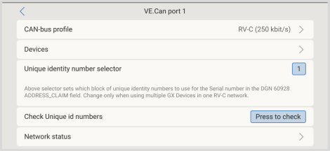 |
21.1.4. RV-C in
Tanks
Tested with Garnet SeeLeveL II 709 and tanks from the RV-C out function of another GX device.
Batteries
Lithionics and BattleBorn are the only supported RV-C batteries (including DVCC support).
Alternators
Support for Wakespeed WS500 (-PRO) and Arco Zeus has been added since v3.xx. For integration with the Lynx Smart BMS (NG) over RV-C, it is mandatory to hardwire the allow-to-charge contact of the BMS to the alternator controller.
21.1.5. Device Classes
This section provides a basic overview of how each device class will participate in the RV-C specification. In any case, "Level 1" integration is largely supported (basic operation), with case-by-case enhancements.
AC standalone Chargers
The AC-based charger class reports its operational status and configuration status using the CHARGER_xx group of RV-C messages. User control must include basic on/off switching via RV-C as well as adjusting shore (AC) power limits.
AC standalone Inverters
This class of AC inverters reports its operational status using the INVERTER_xx group of RV-C reports. Incoming command is limited to on/off (enable/disable) via RV-C.
AC Charger / Inverter
Combined inverter/charger - reports both CHARGER_xx and INVERTER_xx messages.
Solar Controllers
Solar chargers will report their operational status in real time.
SOC Meters
SOC meters can be used to report current battery health via RV-C: voltage, current, temperature, SOC, etc. RV-C requires that only ONE device speaks for a given battery at a time, so if a proper BMS is installed, that will be the data source.
BMS (Victron, or Victron 3rd party supported)
In many cases, the battery(s) in the system will be directly attached to a Victron Cerbo GX, Cerbo-S GX, Nucleo GX, or Ekrano GX, either via Victron equipment or via supported 3rd party compatible BMSs. Such batteries should be represented into the RV-C environment via the DC_SOURCE_STATUSxx messages.
Tank Level meters
Tank meters will be translated into RV-C messages, carrying forward the existing tank ID/ VRM Instance numbers.
21.1.6. Instance Translation
RV-C utilises Instances in several ways:
DC Source Instance
AC Line
Device Instance (context dependent)
Each usage of the Instance has a specific meaning, and a given device may at times utilise one or more of these instances.
DC Source Instance
In RV-C, a DC source is something that can generate and (optionally) store energy. Typically a battery but can also be a fuel cell or the output side of a DC contactor/disconnector.
A DC source can be thought of as a battery system and its associated physical bus, for example, the house battery, the DC bus bar and DC wiring. DC Source Instances are used to associate subsequent devices (e.g. a charger or an inverter) to the ‘DC bus’ it is connected to.
In this way it is possible to map out how all devices are connected with regards to their DC bus via their DC Source Instance value (starter battery and its alternator, house battery and its chargers etc.).
Note that in some cases (e. g. a DC-DC Converter or a Contactor), a device may be associated with two different DC Source instances. For example, a DC-DC converter could be associated with the two different batteries to which it is connected, while a contactor could be associated with the battery to which it is connected; the DC bus on the load side of the contactor then has its own DC Source instance
Though Victron is able to support more than one battery (a house and starter battery), the primary focus is on one battery. The dbus-rvc module will present the ‘primary’ battery to RV-C as ‘DC Source Instance = 1’ (house battery) information.
If present, additional Victron sensing devices will be presented using DC Source Instances of 2. An example is the optional starter battery voltage sensing on SmartShunts.
AC Line
AC line is much simpler, in that RV-C assumes a limited AC system, typically defined as Line 1 or Line 2. Victron supports 3-phase systems, which is not included in the RV-C specification. All installations with 3-phase systems are not supported by the dbus-RVC module and AC-related RV-C messages are suppressed.
Device Instance
Device Instance is a way to separate different physical devices of the same type. Example: if an installation contains two AC chargers attached to the same battery, each would be assigned a separate Device Instance while both would share the same DC Source Instance. Each charger would also be associated with an AC line, which may or may not be the same. In this way the AC charger is fully described in how it is wired on the AC and DC side while being able to be uniquely identified through its Device Instance.
Devices Instances are relevant within a given class of devices. An AC charger can define Device Instances 1 and 2, and these are unrelated to Device Instances 1 and 2 of a DC motor controller.
Note
With the exception of tank monitoring, Device Instances are hard coded as 1 for each specific device class unless specified otherwise in the PGN table. Because the AC charger has a hardcoded instance of 2, to allow coexistance with a inverter/charger with charger instance 1.
21.1.7. RV-C Fault and Error Handling
RV-C fault reporting:
Fault conditions are reported using the DM_RV (0x1FECA) and J1939 DM01 (0x1FECA) DGNs.
In release 1 the operational status bits, the yellow and the red light field are supported because they are stored in DSA.
SPN is set to 0xFFFFFF during normal conditions, and 0x0 at any time a warning or fault condition exists in supported Victron equipment.
FMI is set of 0x1F (Failure mode not available) at all times.
This simple mapping allows external user displays to indicate an alarm or fault condition in a given Victron device, at which time the user should utilise Victron diagnostic aids for additional insight.
21.1.8. RV-C Device Priority
A critical concept in RV-C is the application of Device Priorities.
When used, a given device's priority will impact if it is allowed to transmit DGNs (e.g. a BMS with a higher priority should transmit details of the battery's status, while a MPPT controller with a lower priority should back down).
Device Priority is also at times used to allow for the favouring of one node vs. another, for example, it may be more desirable to use shore power AC vs. the inverter.
In the implementation of dbus-rvc, the following priorities will be hard coded into transmitted messages:
DC_SOURCE_STATUS_xx messages: Priority = 119 (SOC/BMS) to allow native RV-C batteries have a higher priority.
SOLAR_xx messages: Charger Priority = 110
CHARGER_xx messages (Inverter/Chargers):: Charger Priority = 100
CHARGER_xx messages (AC Chargers):: Charger Priority = 80
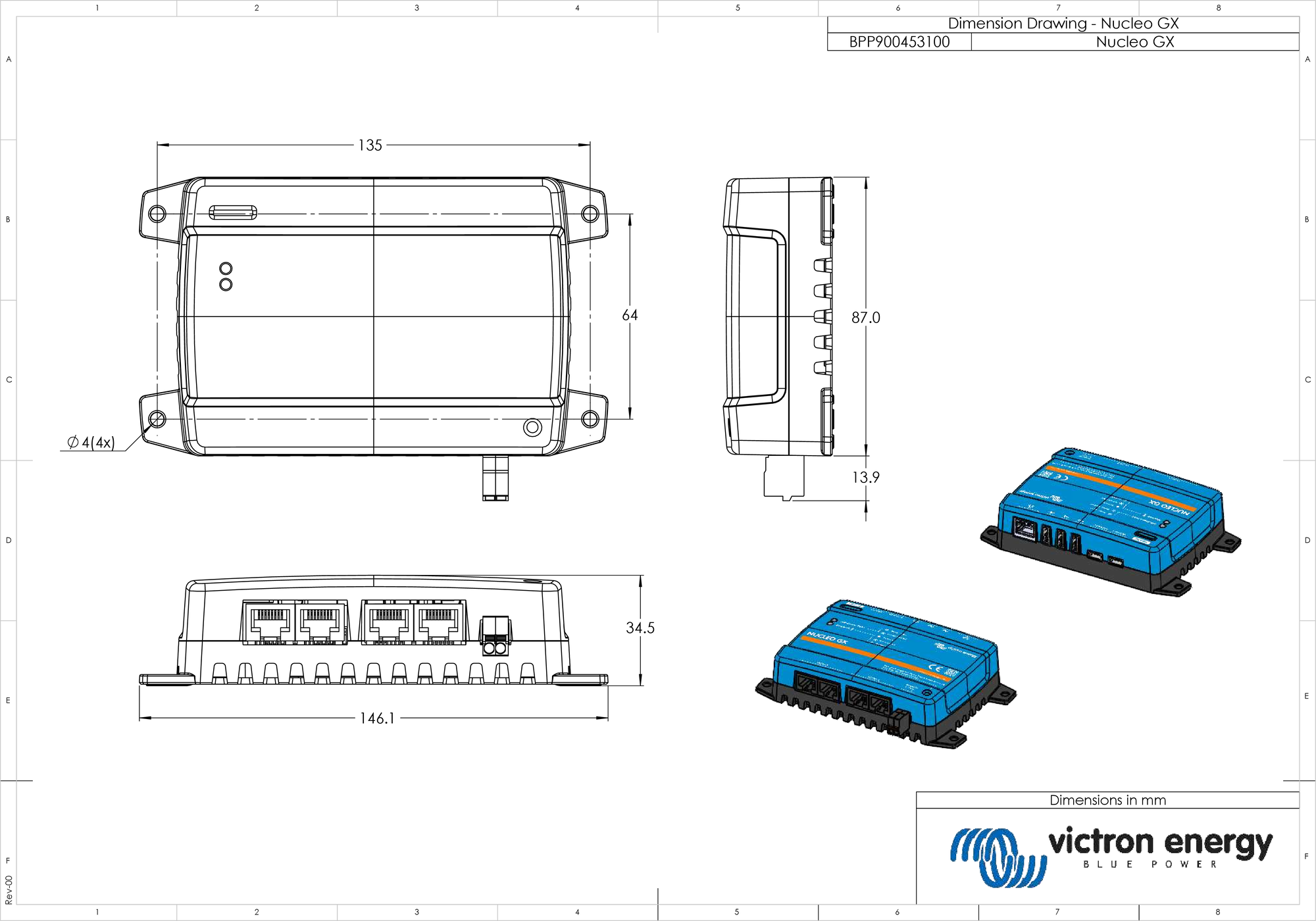
21.2. Nucleo GX Dimensions
21.3. Modbus holding registers for the ComAp InteliLite 4 controller
The following table lists the required ComAp Modbus configuration. In addition to the listed holding registers, Coil 4700 is used to start and stop the genset.
Register(s) | Com. Obj. | Name | DIM | Type | Dec | Group |
|---|---|---|---|---|---|---|
01004 | 10123 | RPM | rpm | int16 | 0 | Engine |
01006 | 9152 | T-Coolant | °C | int16 | 0 | Controller I/O |
01008 | 9151 | P-Oil | bar | int16 | 1 | Controller I/O |
01013 - 01014 | 8206 | Running Hours | h | int32 | 1 | Statistics |
01020 | 8202 | Load P | kW | int16 | 0 | Load |
01021 | 8524 | Load P L1 | kW | int16 | 0 | Load |
01022 | 8525 | Load P L2 | kW | int16 | 0 | Load |
01023 | 8526 | Load P L3 | kW | int16 | 0 | Load |
01036 | 8210 | Generator Frequency | Hz | uint16 | 1 | Generator |
01037 | 8192 | Generator Voltage L1-N | V | uint16 | 0 | Generator |
01038 | 8193 | Generator Voltage L2-N | V | uint16 | 0 | Generator |
01039 | 8194 | Generator Voltage L3-N | V | uint16 | 0 | Generator |
01043 | 8198 | Load Current L1 | A | uint16 | 0 | Load |
01044 | 8199 | Load Current L2 | A | uint16 | 0 | Load |
01045 | 8200 | Load Current L3 | A | uint16 | 0 | Load |
01053 | 8213 | Battery Volts | V | int16 | 1 | Controller I/O |
01055 | 9153 | Fuel Level | % | int16 | 0 | Controller I/O |
01263 - 01264 | 8205 | Genset kWh | kWh | int32 | 0 | Statistics |
01298 | 9244 | Engine State | String list | Info | ||
01301 | 12944 | Connection Type | String list | Info | ||
01307 - 01322 | 24501 | ID String | Long string | Info | ||
01323 - 01330 | 24339 | FW Version | Short string | Info | ||
01382 | 9887 | Controller Mode | string list | Info | ||
03000 - 03007 | 8637 | Gen-Set Name | Short string | Basic Settings / Name | ||
21.4. Modbus holding registers for supported DSE genset controllers
The following table lists the Modbus holding registers the GX device reads. Note that this Modbus table reflects the DSE register list, not the GX device's. These definitions follow the Deep Sea Electronics GenComm standard (Version 2.236 MF). The Modbus register list for reading this data from the GX device can be found in the download section on the Victron website.
The registers marked required in the Remarks column are critical for identifying the DSE genset controllers in the GX device and for proper operation of the Victron ecosystem with the generator. Don't change them. All other registers are optional.
Note: Page and Register offset are terminology from the DSE GenComm standard.
Register(s) | Page | Offset | Name | Units | Remarks |
|---|---|---|---|---|---|
768 | 3 | 0 | Manufacturer code | Required for DSE controller identification | |
769 | 3 | 1 | Model number | ||
770 | 3 | 2 | Serial number | ||
772 | 3 | 4 | Control mode | ||
1024 | 4 | 0 | Oil pressure | kPa | |
1025 | 4 | 1 | Coolant temperature | °C | |
1026 | 4 | 2 | Oil temperature | °C | |
1027 | 4 | 3 | Fuel level | % | |
1029 | 4 | 5 | Engine battery voltage | V | |
1030 | 4 | 6 | Engine speed | RPM | Required for the Victron ecosystem to work properly |
1031 | 4 | 7 | Generator frequency | Hz | |
1032 | 4 | 8 | Generator L1-N voltage | V | |
1034 | 4 | 10 | Generator L2-N voltage | V | |
1036 | 4 | 12 | Generator L3-N voltage | V | |
1044 | 4 | 20 | Generator L1 current | A | |
1046 | 4 | 22 | Generator L2 current | A | |
1048 | 4 | 24 | Generator L3 current | A | |
1052 | 4 | 28 | Generator L1 watts | W | |
1054 | 4 | 30 | Generator L2 watts | W | |
1056 | 4 | 32 | Generator L3 watts | W | |
1536 | 6 | 0 | Generator total watts | W | |
1558 | 6 | 22 | Generator % of full power | % | |
1798 | 7 | 6 | Engine run time | Seconds | |
1800 | 7 | 8 | Generator pos. kW hours | kWh | |
1808 | 7 | 16 | Number of starts | ||
From 2048 | 8 | Alarm conditions | |||
4096 to 4103 | 16 | Control registers | |||
From 39424 | 154 | Alarm conditions |
21.5. Glossary
Terms and abbreviations used throughout the GX Manual, collected here for quick reference. Where a term has a specific meaning in the Victron ecosystem, that meaning is given rather than a generic definition.
fffffff
AC (Alternating Current)
Power that periodically reverses direction, the type supplied by the grid, a generator, or a shore power connection.
Assistant
A small program loaded into a Multi or Quattro through VEConfigure to add specific behavior, such as the ESS Assistant that enables ESS mode, or a current-sensor assistant that reads an external current transformer. Not to be confused with Home Assistant, an unrelated third-party home-automation platform mentioned once in the manual.
BatteryLife
An ESS charge and discharge algorithm, selected as the "Optimized with BatteryLife" mode, that manages a dynamic minimum SoC limit to protect the battery, prioritizing a full recharge during periods of poor solar yield. Its status is reported as one of three states: Self-Consumption, Sustain, or Recharge.
BLE (Bluetooth Low Energy)
The Bluetooth standard used by the GX device and by supported sensors (Mopeka, Ruuvi, Gobius, and others) for short-range wireless connections that draw little power.
BMS (Battery Management System)
The electronics inside or attached to a battery that monitor its condition and, in managed systems, communicate charge and discharge limits (see CVL, CCL, DCL) to the GX device over CAN bus.
BMV
Victron's range of battery monitors. A BMV connected via VE.Direct or VE.Can can act as the SoC (State of Charge) source for the system.
CAN bus
A robust two-wire communication bus used for VE.Can, NMEA 2000, and RV-C. Multiple devices share the same pair of wires and exchange short data messages.
CCGX (Color Control GX)
The GX device model that the Ekrano GX succeeds.
CCL (Charge Current Limit)
The maximum charge current a battery will accept, reported by a managed BMS battery so that connected chargers do not exceed it.
CVL (Charge Voltage Limit)
The maximum charge voltage a battery will accept, reported by a managed BMS battery and followed by connected inverter/chargers and solar chargers when DVCC is active.
DCL (Discharge Current Limit)
The maximum current a managed BMS battery allows to be drawn from it, used by DVCC-capable systems to protect the battery.
DGN (Data Group Number)
The RV-C equivalent of a PGN, a numeric identifier that tells devices on an RV-C network what kind of data a message contains.
DHCP (Dynamic Host Configuration Protocol)
The mechanism most routers use to automatically hand out an IP address to the GX device on a network, as opposed to entering one manually.
Digital input
A physical input on the GX device that reads a simple on or off signal, used for example to detect a bilge pump running, a door switch, or a generator status signal.
DVCC (Distributed Voltage and Current Control)
A GX device setting (Settings, System Setup, Charge Control) that turns the GX device from a passive monitor into an active controller, coordinating charge voltage and current across all connected chargers and the battery.
EEBUS
A European smart-grid communication standard supported by the GX device for interacting with compatible energy devices such as heat pumps.
EGX
Short form for the Ekrano GX.
ESS (Energy Storage System)
A Victron system design for grid-connected installations that requires a Multi or Quattro inverter/charger, a GX device, and a battery, most often paired with solar. It stores solar energy for later use, keeps supplying power during a grid outage, and can automatically import from or export to the grid depending on how it's configured and what local grid rules allow.
EVCS (EV Charging Station)
A Victron electric vehicle charging station that can be monitored and, depending on configuration, controlled by the GX device.
GPS
Used by the GX device (via USB GPS or NMEA 2000 GPS) to provide position and time data, relevant mainly for marine and mobile installations.
GX device
The general term for any Victron communication centre running Venus OS, including the Ekrano GX, Cerbo GX, Cerbo S GX, and Venus GX.
IO Extender
Short for the GX IO-Extender 150, a USB-connected accessory that adds extra relay, digital input, and PWM outputs to a GX device.
IP rating (Ingress Protection rating)
A two-digit code (for example IP43, IP54, IP65) describing how well a device is sealed against dust and water. Higher numbers mean better protection; the manual quotes different ratings for the front and back of the GX housing.
J1939
The underlying CAN bus standard, defined by SAE, that both NMEA 2000 and RV-C are built on top of.
LAN (Local Area Network)
A wired or WiFi network confined to one site, used to reach the GX device's Remote Console without going through the internet.
LTE (Long-Term Evolution)
The technical name for the 4G mobile-data standard. The optional GX LTE 4G accessory, which also falls back to 3G or 2G where 4G coverage isn't available, gives a GX device its own cellular internet connection. It only connects the GX device itself; it does not share that connection with laptops, phones, or other devices.
MFD (Multi-Function Display)
A marine chartplotter or multi-function display, from brands such as Raymarine, Navico, Garmin, or Furuno, that can show Victron system data through either a brand-specific app integration or directly over NMEA 2000.
MK3-USB
A Victron interface used to link a secondary VE.Bus system to a GX device. Systems connected this way are not controlled by DVCC by default.
Modbus TCP
An industrial communication protocol the GX device can expose over the network, used by third-party monitoring or automation systems, and specifically by digital inputs and generator-controller integrations described in the manual.
MPPT (Maximum Power Point Tracking)
Victron's range of solar charge controllers, which optimise the power drawn from a solar array. Connects to the GX device by VE.Direct or VE.Can.
MQTT
A lightweight messaging protocol the GX device can publish data to, used for custom integrations such as home automation or Node-RED.
Multi / Quattro
Shorthand for Victron's MultiPlus and Quattro inverter/chargers, the devices most commonly connected to a GX device over VE.Bus.
NMEA 2000
A marine CAN bus standard (built on J1939) that lets navigation electronics, sensors, and the GX device share data such as tank levels, battery status, and GPS position with a chartplotter or multi-function display.
NO / NC (Normally Open / Normally Closed)
Relay contact states used for the GX device's built-in relays and other relay-controlled wiring, such as generator start and stop signals. Normally Open means the contact stays open until triggered; Normally Closed is the reverse.
Node-RED
A visual programming tool that can run on the GX device to build custom automations and virtual switches beyond what the standard menus offer.
Opportunity Loads
A GX device feature that automatically routes surplus solar power to flexible AC loads (for example an EV charger or water heater) once the battery is sufficiently charged.
PGN (Parameter Group Number)
The NMEA 2000 identifier that tells devices what kind of data a message contains, similar to a message-type number.
Remote Console
The user interface for a GX device, opened over the local network, through the built-in WiFi Access Point, or through VRM.
RGBW / CCT
Lighting output types the GX device can control: RGBW mixes red, green, blue, and white channels for colour lighting, while CCT (Correlated Colour Temperature) adjusts a light between warm and cool white.
RS485
A wired serial communication standard used by some generator controllers (DSE, ComAp, ClearView) and other third-party equipment to connect to a GX device.
RV-C (Recreational Vehicle Controller Area Network)
A CAN bus based protocol, similar in purpose to NMEA 2000, used mainly in North America so RV appliances and control panels can communicate.
SCS (Shared Current Sense)
A DVCC feature where the GX device forwards a measured battery current reading to connected chargers so they do not need their own current sensor.
SoC (State of Charge)
The remaining charge in a battery, shown as a percentage.
STS (Shared Temperature Sense)
A DVCC feature where the GX device forwards a measured battery temperature to connected chargers so they can adjust charging accordingly.
SVS (Shared Voltage Sense)
A DVCC feature, enabled by default, where the GX device selects the most accurate available battery voltage reading and shares it with connected chargers.
TCP / UDP
The two basic ways devices exchange data over a network.
USB
Used on the GX device for firmware updates from a USB stick, for connecting the IO Extender and other Victron USB devices, and for some third-party accessories.
VE.Bus
Victron's proprietary communication bus, mainly used to connect one or more MultiPlus or Quattro inverter/chargers to a GX device.
VE.Can
Victron's implementation of a CAN bus port, used to connect Victron CAN bus devices, or, alternatively, to run NMEA 2000 or RV-C on the same physical port.
VE.Direct
Victron's point-to-point communication port (cable or Bluetooth) used by single devices such as a BMV, an MPPT, an Orion XS, or a Smart IP43 Charger.
Venus OS
The operating system that runs on every GX device.
VRM (Victron Remote Management)
Victron's free cloud portal for monitoring, remote configuration, alarms, and remote firmware updates. Requires the GX device to have an internet connection.
WiFi Access Point
A mode where the GX device creates its own WiFi network so a phone or laptop can connect directly to it without an existing router, useful for first-time setup.