6. Alarms and monitoring
The VRM Portal constantly monitors and watches over your system and can also inform you by email or push notifications if an issue is detected. There are four categories of monitoring:
Communication monitoring: monitors the connection between the VRM Portal and the Victron installation
Automatic alarm monitoring: monitors a predefined list of parameters on all connected products
Geofence: monitors location (requires a GX device with a USB-GPS)
User configurable alarms
The Alarm rules setting can be found under Settings → Alarm rules:
 |
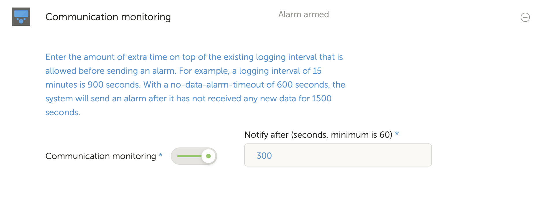
6.1. Communication monitoring
Typically used for stationary installations such as off-grid systems and telecommunication installations where it is important to know that communication between the GX device (i.e. the installation) and the VRM Portal may have been lost.
Available options:
Communication monitoring on/off toggle
Notify after: extend the interval (as been set in the GX device VRM portal online settings for Log interval) that is allowed without data being received before sending a no-data alarm
 |
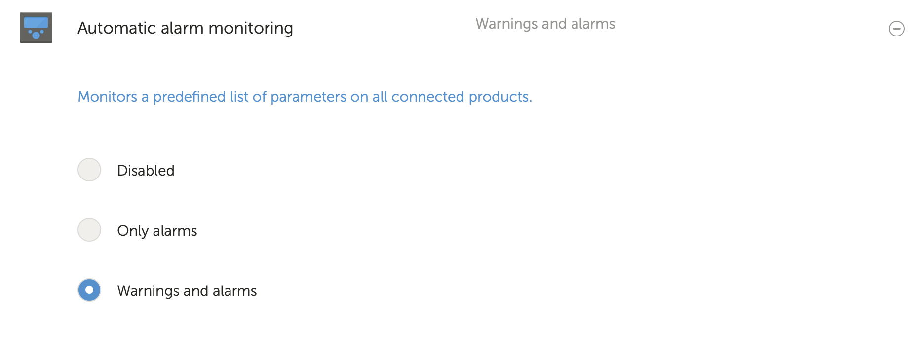
6.2. Automatic alarm monitoring
Monitors a predefined list of parameters on all connected products. With this feature, it is not necessary to manually configure alarm rules for all the different parameters. A notification will be sent if any of the parameters listed below enters an Alarm state, and optionally for Warnings too. A recovery notification will be sent if the parameter returns to its normal value.
This is set to Only alarms by default.
Available options:
Disabled: disables the Automatic alarm monitoring
Only alarms: send notifications for alarms only
Warnings and alarms: send notifications for warning and alarms
 |
6.3. Parameters being watched by the Automatic alarm monitor
6.3.1. VE.Bus products (Multi, Inverter and Quattro)
VE.Bus state
VE.Bus Error
Temperature alarm
Low battery alarm
Overload alarm
AC Input phase rotation (for three phase systems)
6.3.2. BMV, Lynx Shunt VE.Can and other batteries
High voltage alarm
Low voltage alarm
High starter-voltage alarm
Low state-of-charge alarm
Low battery temperature alarm (BMV-702 only)
High battery temperature alarm (BMV-702 only)
Mid-voltage alarm (BMV-702 only)
Low fused-voltage alarm (Lynx Shunt only)
High fused-voltage alarm (Lynx Shunt only)
Fuse blown alarm (Lynx Shunt only)
High internal-temperature alarm (Lynx Shunt only)
Low starter-voltage alarm (Lynx Shunt only)
High charge current alarm
High discharge current alarm
Cell imbalance alarm
Internal error alarm
6.3.3. Lynx Ion BMS
Error code
Error
6.3.4. Solar charger
Charger fault
Charge state
Equalization pending
Alarm condition
Low voltage alarm
High voltage alarm
Error code
6.3.5. Skylla-i charger
Charger fault
Charge state
Error
Low voltage alarm
High voltage alarm
6.3.6. Venus devices
Digital input
6.3.7. Generator start/stop
Generator not detected at AC-input. See GX - Generator auto start/stop manual for details.
6.3.8. Inverter RS, Multi RS models
High temperature alarm
High voltage DC alarm
High voltage AC out alarm
Low temperature alarm
Low voltage DC alarm
Low voltage AC out alarm
Overload alarm
Ripple alarm
6.4. User configurable alarms step-by-step
Advanced rules, including hysteresis, can be configured for all parameters available in the VRM database.
 |
Go to Settings → Alarm rules and click on Add new alarm rule.
Select the device for which you want to create a new alarm rule.
Select the parameter to be monitored.
Configure high, low values and their hysteresis (see How to properly configure high, low and their hysteresis).
Set the notification time and then save the new alarm rule. Use this to avoid spikes in data from causing nuisance alarms, for example tank levels in mobile applications, where a pump running can cause a temporary low alarm on pressure based level sensors located on the pump suction pipe.
As soon as the new alarm rule is saved, it is armed. To delete the alarm rule, click on Delete alarm.
6.5. How to properly configure high, low alarms and their hysteresis
The hysteresis is important to prevent the nuisance clearing and re-triggering of an alarm state when the system is close to the trigger. Consider the following example: you want an alarm as soon as the battery voltage drops below 10V that only clears when the voltage rises again above 11.5V. The hysteresis is 11.5V
A properly configured alarm rule meets the following criteria:
The low hysteresis should be equal to or higher than the low alarm threshold.
The high hysteresis should be equal to or lower than the high alarm threshold.
The low hysteresis should be lower than the high alarm threshold (otherwise a high alarm will be triggered as soon as the low alarm is cleared).
The high hysteresis should be higher than the low alarm threshold.
Taken together, these rules should ensure that alarms don't frequently toggle on and off due to minor fluctuations around the threshold values.
6.6. Receiving an alarm on mains failure
This alarm is typically wanted when a mains grid is normally expected to be available.
Depending on if the system is an ESS system, or a backup system (without ESS) this alarm is configured differently.
The following steps are required to set it up:
Primary method via GX device
On the GX device, go to Settings → System setup
Set AC input type to 'Grid'
Set 'Monitor for grid failure' to 'Enabled'
Alternative method via VRM alarm rules
In VRM; go to Settings → Alarm rules and click on Add new alarm rule.
Select the Multi (or Quattro) as the device on which you want to monitor a parameter.
Select VE.Bus State as the parameter.
Set the Inverting state as 'Armed'. You might want to add Off and Fault there as well.
Set the notification time to 300 seconds, i.e. 5 minutes.
Save the alarm rule.
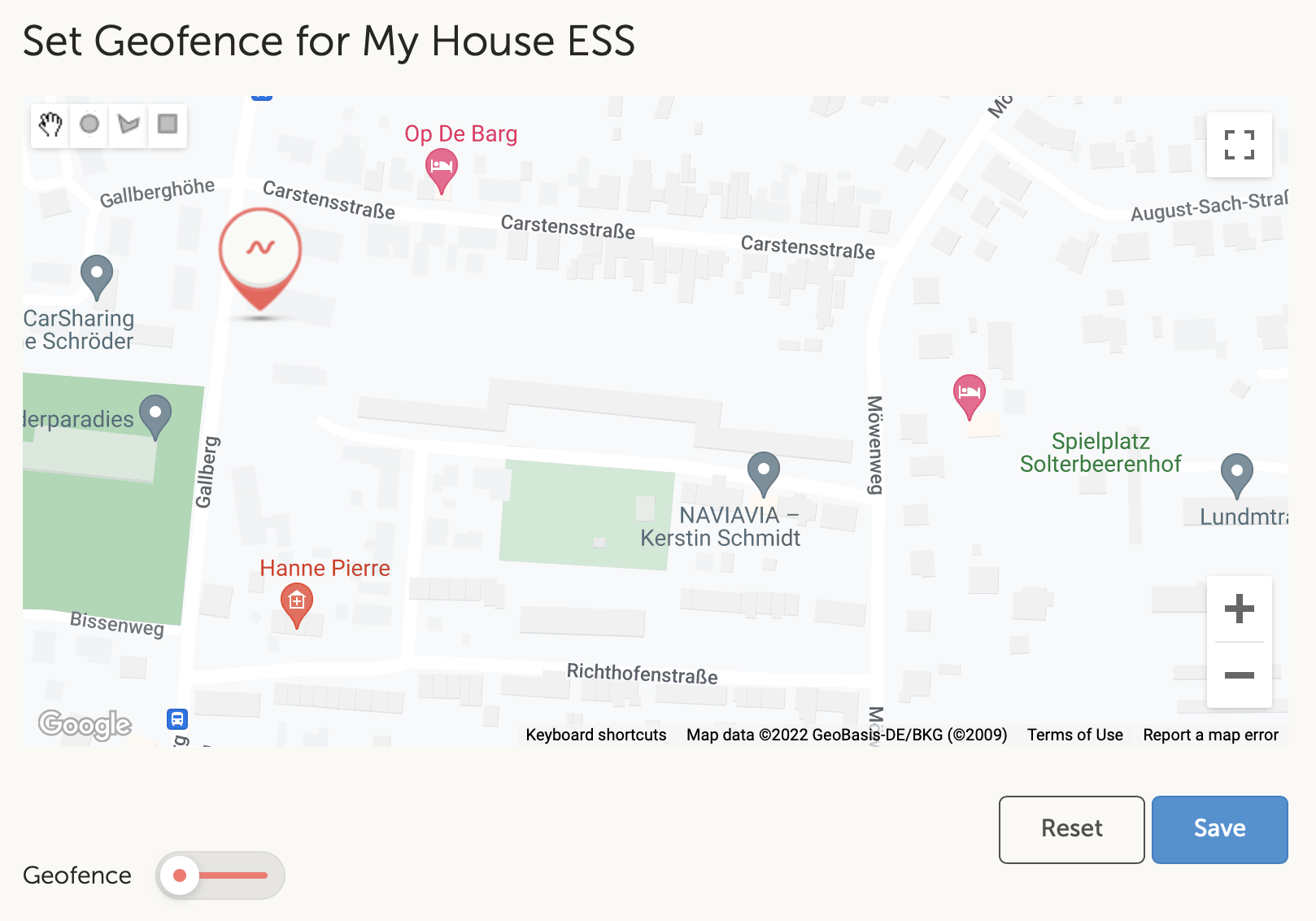
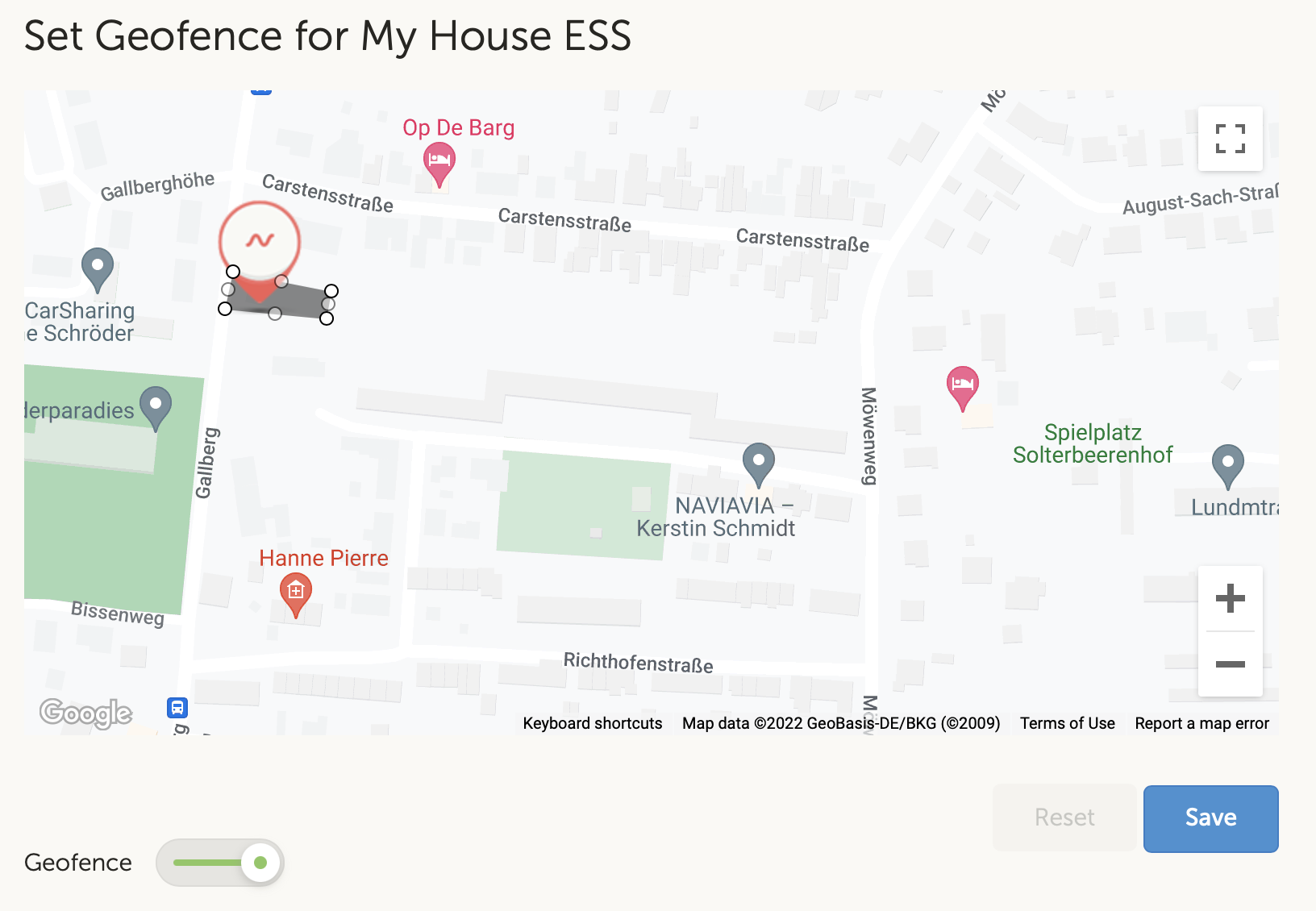
6.7. Geofence
Typically used for RVs and boats. The example below shows a Geofence that will give an alert when the RV leaves the designated parking space. An alarm will also be generated when the location data is no longer being received, for example when the GPS receiver is unplugged. Use this in combination with the Communication monitoring alarm for full coverage.
Steps to configure a Geofence:
Go to Settings → Geofence and click on Set geofence.
Draw a circle, shape or rectangle (available at top left) around the current GPS position (marked with a teardrop shape icon with a sine wave inside). Note that it is also possible to draw Irregular shapes with the shape tool.
Once the Geofence is saved, it is armed. Use the slider on the bottom left to disable the Geofence alarm before moving the RV or boat out of position.
 |
 |
6.8. Notifications
When a warning or alarm is triggered on an installation that you are monitoring on VRM, an alarm notification is sent. To receive these alarm notifications, you must configure what type of notification you want to receive for alarms. There are three notification types:
Email
VRM App push notifications directly to the notification center of a mobile phone, tablet or Apple laptop
Web push notifications to a browser such as Google Chrome or Safari on Windows and macOS.
Note that the Rate limiter is also active for push notifications.
The following chapter describes how to set up notifications per type.
6.8.1. How to set up push notifications on a mobile device
Install (or update) the VRM App on your phone, table or Apple laptop (with Apple M1 or later)
Allow VRM to send notifications
After a fresh install or update, a popup will appear asking if you want to allow push notifications. If you do not allow this, this can be done later in the app settings of the device. On Android notifications are enabled by default.
Login to your VRM account. The installation overview is then displayed.
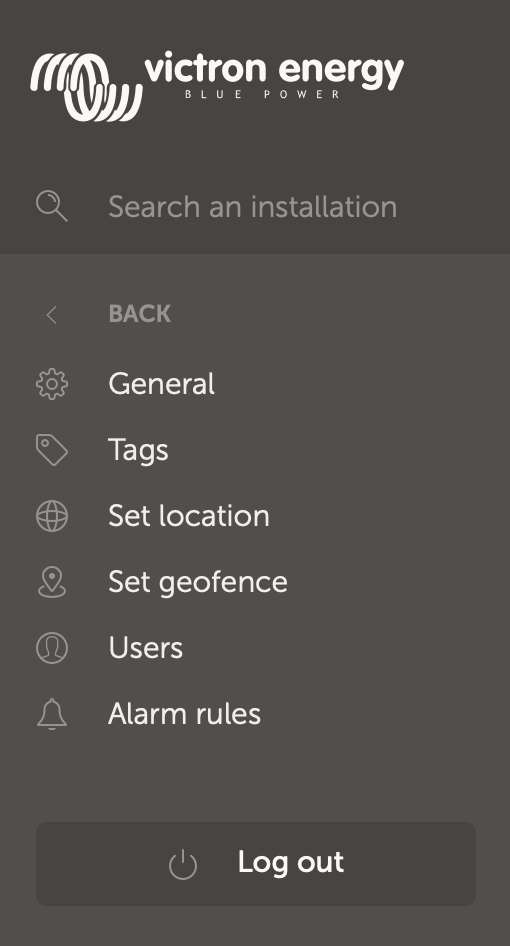
Tap the menu bar in the top left and then tap on 'BACK' to get to the Preferences menu.
Tap Preferences and then tap Notifications.
If you have allowed VRM to send notifications, mobile push notifications will be automatically enabled for that specific device as can be seen in the image below.

In addition, all devices that have push notifications enabled are listed under 'Other devices', from where you can also remove push notifications for specific devices or browsers.

Make sure it works; Tap on Send a test notification.
All devices and browsers that have push notifications for VRM enabled should receive the test notification.
Note that it works in a similar way with an Apple laptop (M1 and later) that has the VRM App installed from the App Store, except that it identifies itself as an iPad.
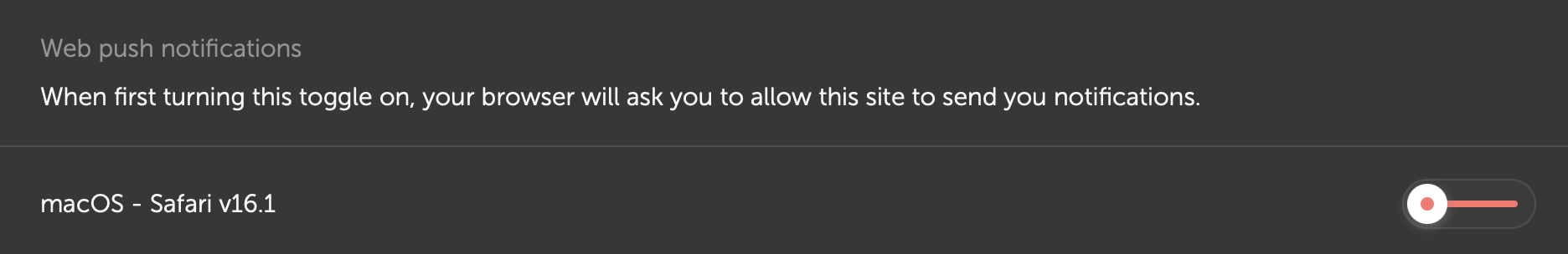
6.8.2. How to set up web push notifications in a browser
Push notifications can also be enabled for a web browser like Apple Safari, Google Chrome and others on macOS and Windows. This chapter explains the steps to do this.
Login to your VRM account via a web browser.
Click on 'BACK' in the top left.
Click Preferences and then click Notifications.
In 'Notification settings for this device' under 'Web push notifications' the browser is already listed but not activated yet. Toggle the slider to turn on web push notifications.
When you enable the toggle for the first time, your browser will ask you if you want to allow the VRM URL to send you notifications. You will only be asked for it once. If permission is not granted, this can be done later in the settings of the browser app (see also the FAQ Why can't I get push notifications in my Google Chrome browser on a Apple Mac?).
Make sure it works; Tap on Send a test notification.
All devices and browsers that have push notifications for VRM enabled should receive the test notification.
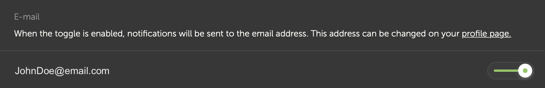
6.8.3. How to set up email notifications
In contrast to push notifications, which have to be set up per device, it is sufficient to turn on email notifications on any device. These are then automatically active on all other devices. The following steps are necessary to enable email notifications.
Open the VRM App or login to your VRM account on a web browser.
Tap/click on 'BACK' in the left menu.
Tap Preferences and then tap Notifications.
Click the toggle in 'Notification settings for this device' under 'E-mail' to enable email notifications.
Make sure it works; Tap on Send a test notification.
You should receive the test notification via email.
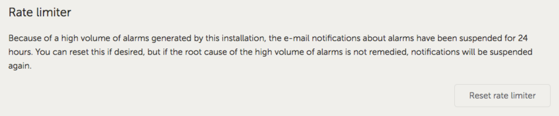
6.8.4. Email and push notification rate limiter
Under certain conditions, some installations can hover near a warning or alarm condition. This can yield a flow of redundant email and/or push notification messages, leading to user alarm fatigue and spam false positives, not to mention an overflowing inbox.
In case the system detects that this is going on, it will send one last email out, which contains a warning that due to rate limiting it will stop sending out new emails.
In case the flood of alarms ceases, the system will automatically resume sending out emails after 24 hours.
The rate limiter can also be reset manually on the VRM Portal:
In VRM go to the installation
Go to Settings → Alarm rules
In case the rate limiter is active, you'll see the below image.
Click on Reset rate limiter.
 |