8. Appendix
8.1. Appendix A
Loads which can be controlled directly by the Load disconnect output of the VE.Bus BMS NG:
Inverters:
All Inverters VE.Direct and Inverters Smart. Connect the Load disconnect output of the BMS to terminal H of the 2-pole connector of the inverter.
DC-DC converters:
All Tr-type DC-DC converters with remote on/off connector, the Orion 12/24-20 and the Orion XS. Connect the Load disconnect output of the BMS to the right-hand terminal of the 2-pole connector.
BatteryProtect and Smart BatteryProtect:
Connect the Load disconnect output of the BMS to terminal 2.1 (right hand terminal) for the BatteryProtect and H pin of the 2-pole connectorfor the Smart BatteryProtect.
Cyrix-Li-Load:
Connect the Load disconnect output of the BMS to the control input of the Cyrix.
Loads for which an inverting remote on-off cable is needed (article number ASS030550100 or -120):
VE.Bus inverters and VE.Bus Inverter Compact rated at 1200VA or more
Solar charge controllers which can be controlled directly by the Charge disconnect output:
BlueSolar MPPT 150/70 and 150/80 CAN-bus:
Connect the Charge disconnect output of the BMS to the left hand terminal of the 2-pole connector (B+).
SmartSolar MPPT 150/45 and higher, 250/60 and higher
Connect the Charge disconnect output of the BMS to the right-hand terminal (marked +) or the left-hand terminal (marked H) of the 2-pole connector
Solar charge controllers for which a VE.Direct non-inverting remote on-off cable is needed (article number ASS030550320):
BlueSolar MPPT models except the BlueSolar MPPT 150/70 and 150/80 CAN-bus
SmartSolar MPPT up to 150/35
Battery Chargers:
Smart IP43 Chargers:
Connect the Charge disconnect output of the BMS to terminal H of the 2-pole connector.
Skylla TG battery chargers:
Use a non-inverting remote on-off cable (article number ASS030550200).
Skylla-i battery chargers:
Use a Skylla-i remote on-off cable (article number ASS030550400).
Other battery chargers:
Use a Cyrix-Li-Charge.
8.2. Displaying VE.Bus BMS NG SoC on a GX Device
Unlike the VE.Bus BMS V2, the VE.Bus BMS NG transmits State of Charge (SoC) over the VE.Bus network. This guide explains how to enable and display the SoC on a GX device.
Notice
Enabling this feature adds only the SoC. No other BMS parameters are forwarded to the GX device.
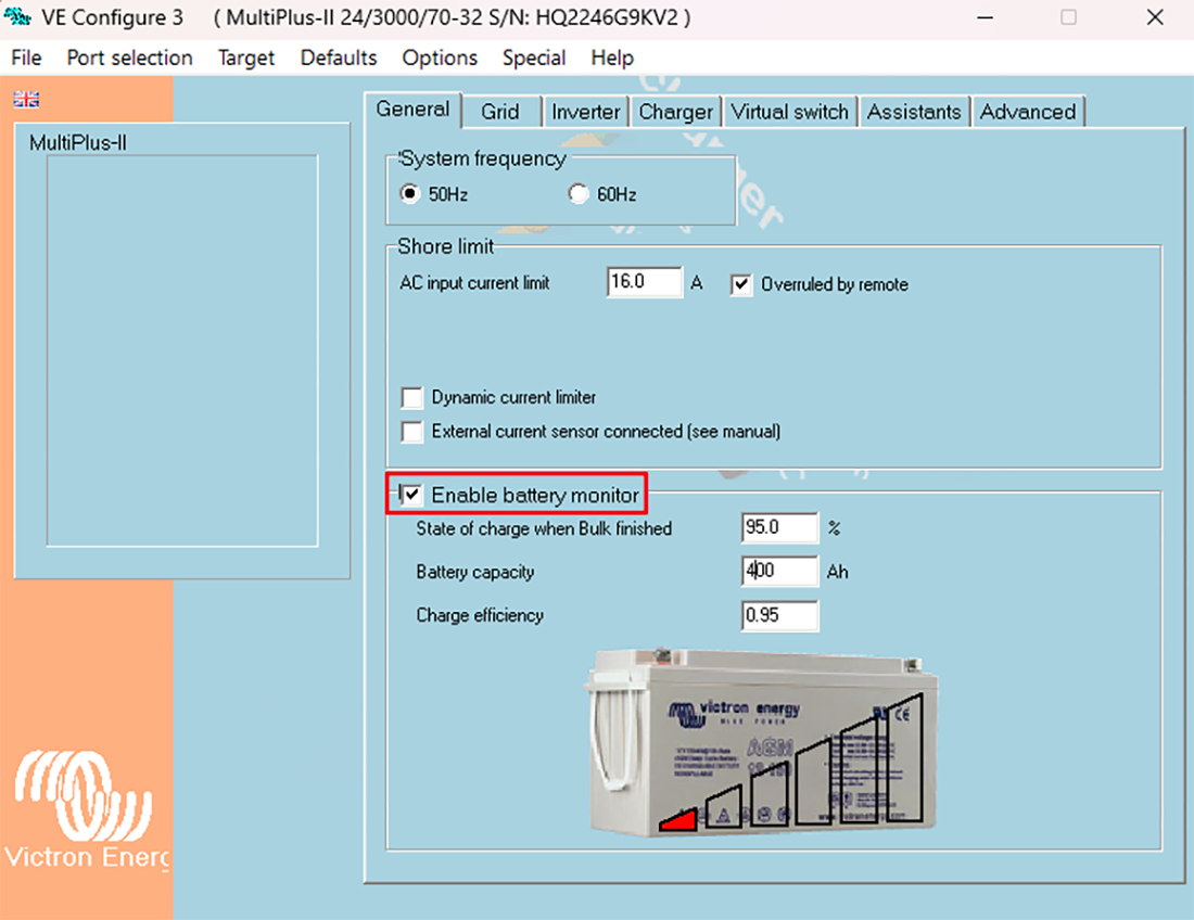
Enable “Battery Monitor” on the MultiPlus/Quattro
To forward SoC to the GX device, you must enable the Battery Monitor setting on the MultiPlus/Quattro. This can be done via Remote VEConfigure or VictronConnect.
Using Remote VEConfigure
|  |
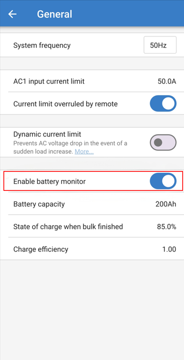
Using VictronConnect
|
|
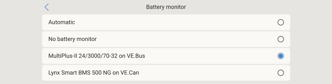
Selecting the battery monitor in the GX device
This step is only required if multiple battery monitoring devices are connected to the GX device. In such cases, ensure that the MultiPlus/Quattro is selected as the active battery monitor:
|  |
8.3. Powering the VE.Bus BMS NG without a connected Multi
In situations where the VE.Bus BMS NG must be operational wihtout a connected Multi, it can be powered independently.
Step-by-step
Connect a DC power supply between:
Pin 3 (GND) of either RJ45 socket on the VE.Bus BMS NG — the sockets are internally connected, so using one is sufficient — and
+Bat terminal on the Phoenix 6-pin connector.
Ensure correct polarity and supply voltage according to Technical specifications VE.Bus BMS NG.
When powered, the VE.Bus BMS NG initialises and battery data becomes available via VictronConnect.

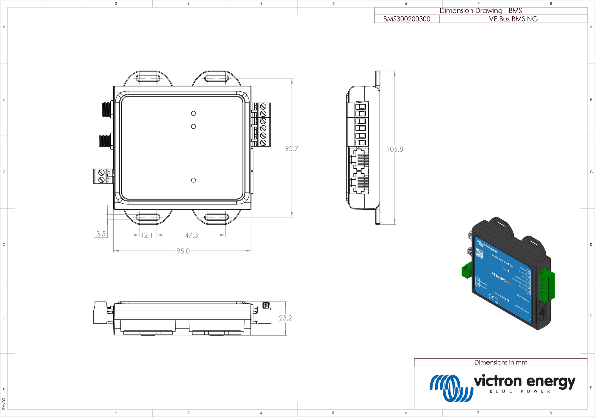
8.4. Enclosure dimensions VE.Bus BMS NG