Wiring
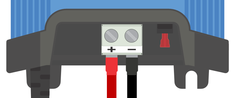
Connect DC power cabling between the Blue Smart IP22 Chargers BATTERY terminals (located under the lower connection cover) and the battery/batteries or DC system distribution bus.
Ensure that the DC system is fully shut down (all DC loads and charge sources off/isolated) prior to disconnection of any existing battery/DC system distribution bus cabling and connection of the charger to the battery terminals/DC system distribution bus.
Use flexible multi stranded copper DC power cable with sufficient cross sectional area, inline with an appropriate fuse or circuit breaker; refer to the 'Installation > Wiring > DC power cable' and 'Installation > Wiring > Overcurrent protection' sections for more information.
Ensure that wiring polarity is correct; use red cabling for the + (positive) connections and black cabling for the - (negative) connections.
Torque the terminal screws to 2.4Nm using a small torque wrench with a suitable screw driver bit, and reinstall the lower connection cover.
Connect the AC power cable to a mains power outlet; after a short delay, the LEDs indicating the current charge mode and charge state will illuminate.

Example wiring schematics for most typical installation configurations have been provided - refer to the 'Installation > Schematics' section for more information.