4. Installation
4.1. Unpacking and handling the battery
Take care when unpacking the battery. Batteries are heavy. Do not lift the battery by its terminals or by its BMS cables. The battery has two carry handles on either side of the battery. The weight of the battery can be found in the Technical data chapter.
Familiarise yourself with the battery. The main battery terminals on the top have a “+” symbol for positive and a “-” symbol for negative to ensure correct polarity.
Each battery has two BMS cables for communicating with the BMS. One cable has a male 3-pole connector, and the other has a female 3-pole connector. Depending on the battery model, the BMS cables are located on one side of the battery or two opposite sides of the battery.
Ensure that the BMS cables do not get snagged or damaged when handling the battery.
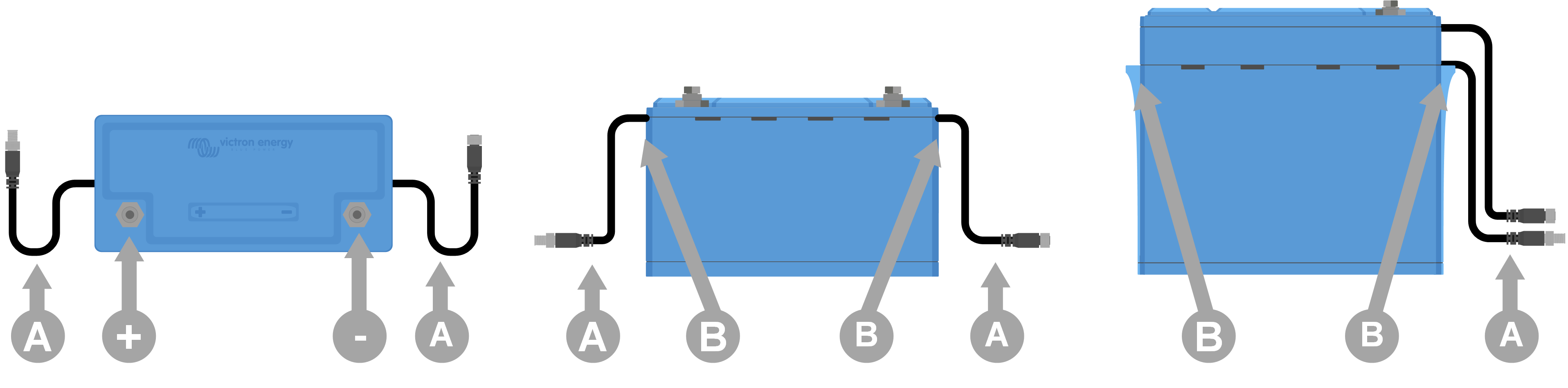 |
Top view and side views showing battery terminals (+ and -), BMS cables (A), and carry handles (B)
4.2. Download and install the VictronConnect app
Download the VictronConnect app for Android, iOS or macOS from their respective app stores. For more information about the app, see the VictronConnect product page.
 |
The VictronConnect app communicates with the battery via Bluetooth
4.2.1. Update the battery firmware
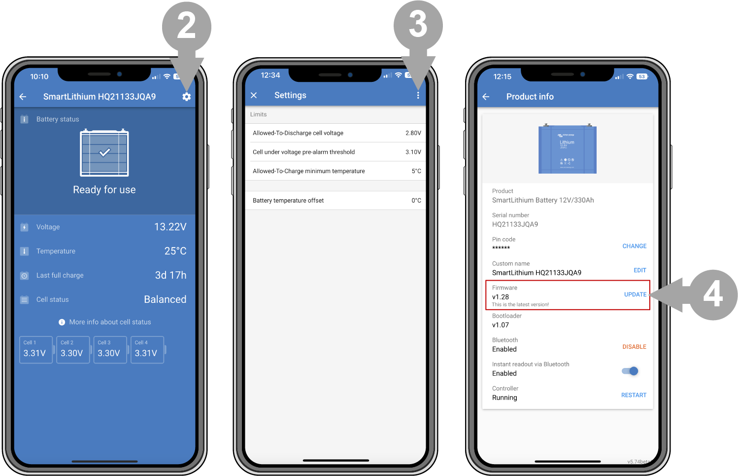
Before the battery is going to be used, it is important to check if the battery has the most up-to-date firmware. The firmware can be checked and updated with the VictronConnect app. Also, make sure you have the latest VictronConnect version. This ensures that the latest battery firmware version is available.
The VictronConnect app might ask, on first connection, to update the firmware. If this is the case, let it perform a firmware update. If it did not automatically update, check if the firmware is already up to date using the following procedure:
|
|

4.3. Initial charging before use
4.3.1. Why charge batteries before use
Lithium batteries are only approximately 50% charged when shipped from the factory. This is a transportation safety requirement. However, due to differences in transportation routes and warehousing, the batteries do not always have the same state of charge by the time they are installed.
The built-in battery cell balancing system is only able to correct small differences in state of charge from one battery to another. New batteries can have large state of charge differences between them that won't be corrected if installed that way, especially when connected in series. Please note that differences in state of charge between batteries is not the same thing as imbalances between cell voltages within a battery. This is because the cell balancing circuits in one battery cannot affect the cells in another battery. For more in-depth details on cell balancing refer to the Cell balancing chapter.
4.3.2. How to charge batteries before use
Warning
Always use a BMS-controlled charger when individually charging lithium batteries.
If, for a specific reason, the initial charge procedure needs to be performed without a BMS (not recommended), check the Initial charge procedure without BMS chapter in the appendix for details.
Initial charge procedure:
If a battery bank will consist of batteries connected in series to make a higher voltage bank, then each battery must be charged individually first. Use a dedicated charger or an inverter/charger with a BMS to perform the initial charge.
Only a single battery or a bank of parallel connected batteries can be charged as one.
Refer to the BMS manual on how to set the BMS up.
Set the charger to the charge profile as indicated in the Charger settings section.
Ensure that the battery, the BMS and the charger are communicating with each other. Check this by disconnecting one of the battery BMS cables from the BMS and verifying that the charger turns off. Then reconnect the BMS cable and verify that the charger turns back on.
Turn the charger on and check that the charger is charging the battery.
Note that if, during charging, there is any imbalance between the battery cells then the BMS may turn the charger off and on repeatedly. You may notice that the charger is turned off for a few minutes and then on again for a short period of time before being turned off again. Don't be alarmed, this pattern will repeat itself until the cells are balanced. If the cells are balanced then the charger will not turn off until the battery is fully charged.
The battery is fully charged when the battery charger has reached the float stage and the VictronConnect app battery cell status is "balanced". In case the battery cell status is "unknown" or "imbalanced", then the battery charger will be restarted multiple times until the battery cell status is "balanced". The different statuses are described in the Cell balancing chapter.
 |
Initial charge using a BMS
4.4. Mounting
Mounting must meet the following requirements:
The battery can be mounted upright or on its side, but not with the battery terminals facing down. Note that this does not apply to the 12.8V/330Ah model, which can only be installed upright.
The battery is only suitable for indoor use and needs to be installed in a dry location.
Batteries are heavy. When moving the battery into its destined location, use suitable handling equipment for transportation.
Ensure adequate and secure mounting, as the battery can become a projectile if involved in a vehicle accident.
Batteries produce a certain amount of heat when they are charged or discharged. Keep a 20mm space on all four sides of the battery for ventilation.
4.5. Connecting battery cables
Observe the battery polarity when connecting the battery terminals to a DC system or other batteries. Take care not to short-circuit the battery terminals.
Connect the cables as indicated in the diagram:
| 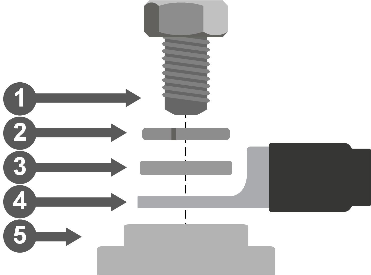 Battery cable connection | 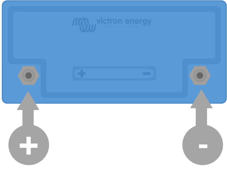 Battery terminals |
When tightening the bolts, use the correct torque indicated in the table and use insulated tools that match the bolt head size.
Battery model | Thread | Torque |
|---|---|---|
12.8V - 50Ah, 60Ah, 100Ah and 25.6V - 100Ah | M8 | 10Nm |
12.8V - 160Ah, 200Ah and 25.6V - 200Ah | M8 | 14Nm |
12.8V - 300Ah, 330Ah | M10 | 20Nm |
4.5.1. Cable cross-sectional area and fuse ratings
Use battery cables with a cross-sectional area that matches the currents that can be expected in the battery system.
Batteries can produce very large currents; it is essential that all electrical connections to the battery are fused.
The battery cables must be sized to carry the maximum expected system current. An appropriately rated fuse for the battery cable size must be used.
For more information on cable cross-sectional area, fuse types and fuse ratings see the Wiring Unlimited book.
The battery maximum discharge rating is indicated in the Technical data table. The system current and therefore the fuse rating should not exceed this current rating. The fuse has to match the lowest current rating, that being the cable current rating, the battery current rating or the system current rating.
4.5.2. Connecting a single battery
|
Single battery |

4.5.3. Connecting multiple batteries in series
|
Multiple batteries in series |

4.5.4. Connecting multiple batteries in parallel
|
Multiple batteries in parallel |

4.5.5. Connecting multiple batteries in series/parallel
|
Multiple batteries in series/parallel
Do not interconnect midpoints nor connect anything else at the midpoints |


4.5.6. Battery banks consisting of different batteries
When constructing a battery bank, ideally, all batteries should be of the same capacity, age and model. However, there are situations where this is not possible, such as when capacity needs to be expanded by adding more batteries or when a single battery in a battery bank needs to be replaced. In these cases, follow the guidelines in the table below.
Battery bank type | Different capacities allowed? | Different ages allowed? |
|---|---|---|
Parallel | Yes | Yes |
Series | No1) | Yes2) |
Series/parallel - within a series string | No1) | Yes2) |
Series/parallel - in case a whole series string is replaced or added | Yes | Yes |
1) All batteries must have the same capacity rating and the same part number 2) The age difference should not exceed 3 years | ||
Background information:
Due to old batteries having reduced capacity, connecting them in series with new batteries or connecting different capacity batteries in series will result in an imbalance between the batteries. This imbalance will increase over time and cause an overall reduction in battery bank capacity. Theoretically, the battery with the lowest capacity would determine the overall capacity of a series string, but in reality, the overall series string capacity will reduce further over time. For example, if a 50Ah battery is connected in series with a 100Ah battery, the overall string capacity is 50Ah. But over time, the batteries become imbalanced, and when the imbalance has become, let's say, 10Ah, the overall battery capacity will be 50Ah-10Ah = 40Ah. The cells of the fullest battery will have an overvoltage during charging, while they are not able to send the excess voltage to the other battery cells. The BMS will constantly interfere, resulting in the emptiest battery is being discharged too deeply and the fullest battery is being overcharged.
Tip
Adding a Battery Balancer to a series string will reduce imbalance.
4.6. Connecting the BMS
Each battery has two BMS cables with an M8 male and M8 female connector that need to be connected to the BMS.
BMS cables on either side or on one side |
Female and male BMS connector
Connected BMS connectors |


How to connect the cables:
For a single battery, connect both BTV cables directly to the BMS.
For a battery bank consisting of multiple batteries, interconnect each battery (daisy chain) and connect the first and last BTV cable to the BMS. The batteries can be interconnected in any order.
If the BMS is too far away for the cables to reach, use the optional extension cables. The BTV extension cables are available as a pair and come in a variety of lengths. For more information see the BTV extension cable product page.
 Single battery BMS connection | 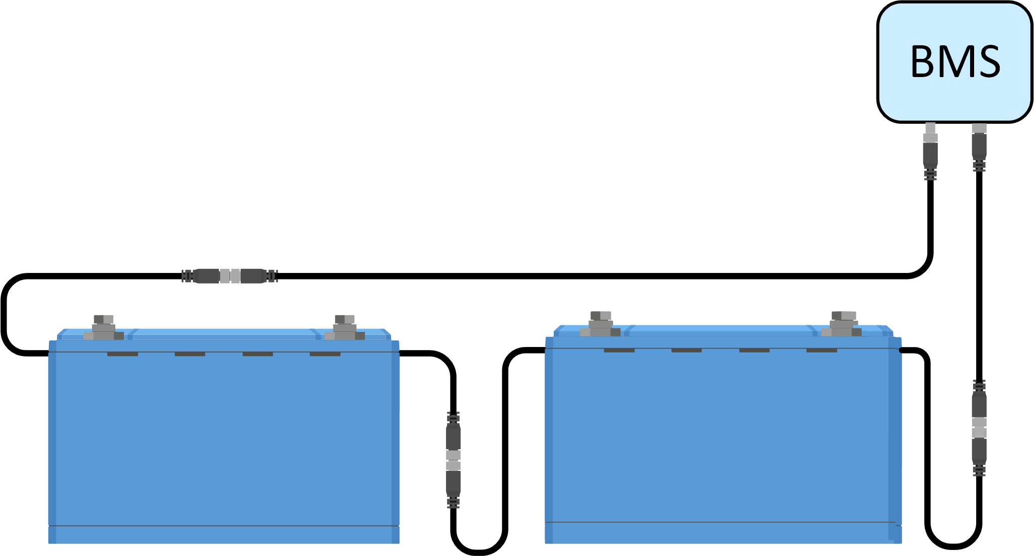 Two battery BMS connection (with optional extension cables) | 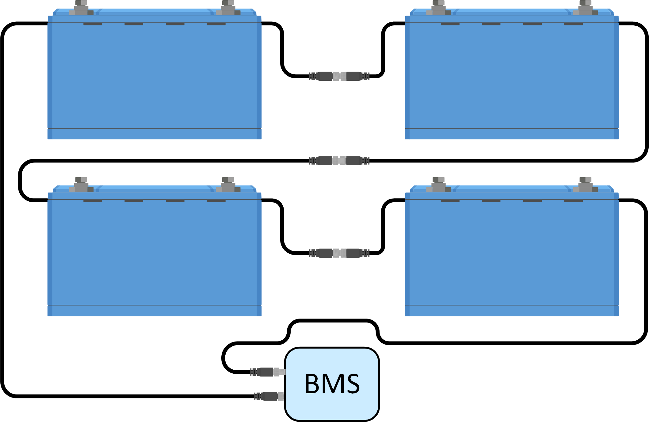 Multiple battery BMS connection |
4.7. Battery settings and configuration via VictronConnect
4.7.1. Battery settings
The default settings in the battery are suitable for almost all applications. There is no need to change these settings unless the application requires very specific conditions.
If settings need to be changed, use the VictronConnect app. To access the settings, click on the settings symbol  .
.
 |
VictronConnect battery settings
4.7.2. Battery temperature offset
This setting can be used to set an offset to improve the accuracy of the battery temperature measurement.
The default value is 0°C, and the range is -10°C to +10°C.
4.7.3. Allowed-To-Charge minimum temperature
This setting defines the lowest temperature at which the BMS allows battery charging.
A lithium battery cell will sustain permanent damage when charged at temperatures below 5°C.
The default value is 5°C and the range is -20°C to +20°C.
Warning
Setting this temperature below 5°C will void the warranty.
4.7.4. Cell under voltage pre-alarm threshold
A pre-alarm signal is sent to the BMS when the cell voltage drops below this threshold. The purpose of the pre-alarm is to warn the user that the system is about to shut down due to undervoltage. For more details, see chapter The pre-alarm signal.
The default value is 3.10 V, and the range is 2.80V to 3.15V.
If the pre-alarm threshold is set at a higher voltage, the warning will come earlier than when set at a lower voltage. An earlier warning will give the user more time to take action and avert the imminent shutdown. In any case, there are at least 30 seconds between pre-alarm and system shutdown.
4.7.5. Allowed-To-Discharge cell voltage
A lithium battery cell will be damaged if the cell voltage drops too low. To avoid this, the BMS will disable all loads by sending a signal to the load or the load disconnection device as soon as one of the cells reaches the set Allowed-To-Discharge voltage threshold.
Default value (the lowest battery cell voltage at which discharging the battery is disallowed): 2.80V (range 2.60 to 2.80V)
We recommend not to change this setting. The only scenario where a lower setting might be applicable is in emergency systems, where it could be a requirement to discharge the battery as far as possible and therefore sacrifice part of the battery's overall lifetime.
If the Allowed-To-Discharge cell voltage is set to a low value, there will be less reserve capacity than when it is set at a higher value, for example:
At 2.8V cell voltage, the battery has approximately 3% remaining capacity.
At 2.6V, there is about 1% remaining capacity in the battery.
Caution
More reserve capacity is important. When there is less reserve capacity, the battery will need to be recharged almost straight away after a low voltage shutdown has occurred. If the battery is not recharged, it will further discharge due to self-discharge and quickly reach the point where one or more cells are damaged due to low cell voltage. This will lead to a permanent reduction of battery capacity and/or lifetime.
4.8. Charger settings
The recommended charging parameters for the charging sources are:
For 12.8V models: 14.20V absorption voltage, 2 hours absorption time and 13.50V float voltage
For 25.6V models: 28.40V absorption voltage, 2 hours absorption time and 27.00V float voltage
For the recommended charge currents please see the Charging the battery and recommended charger settings chapter and refer to the table in the Technical data chapter.
For more information on the charging settings of the individual chargers or inverters/chargers, please refer to the manuals on the respective product page.
4.9. Commissioning
Once all connections have been made, the system wiring needs to be checked, the system needs to be powered up, and the BMS functionality needs to be checked. Follow this checklist:
 | Check the polarity of all battery cables. |
| Check the cross-sectional area of all battery cables. |
| Check if all battery cable lugs have been crimped correctly. |
| Check if all battery cable connections are tight (don’t exceed maximum torque). |
| Tug slightly on each battery cable and see if the connections are tight. |
| Check all BMS cable connections and make sure the connector screw rings are screwed all the way down. |
| Connect with VictronConnect to each battery. |
| Check if each battery has the most up-to-date firmware. |
| Check if each battery has the same settings. |
| Connect the system positive and negative DC cable to the battery (or battery bank). |
| Check the string fuse(s) rating (if applicable). |
| Install the string fuse(s) (if applicable). |
| Check the main fuse rating. |
| Install the main fuse. |
| Check if all battery charge sources have been set to the correct charge settings. |
| Turn on all battery chargers and all loads. |
| Check if the BMS is powered up. |
| Disconnect a random BMS cable and verify that the BMS is turning off all charge sources and all loads. |
| Reconnect the BMS cable and check if all charge sources and loads turn back on. |