Setup menu
To enter the configuration mode, press the button on the back of the control panel for about 4 seconds until the bottom LED in the right column starts blinking, indicating that the first parameter can be changed.
To change the value of a parameter, turn the knob until the displayed value is as required.
Press the configuration button to advance to the next parameter.
Pressing the configuration button, after the last parameter is selected, will exit configuration mode and activate all parameters. So even if only one parameter needs adjustment, you will have to go through all parameters.
When the configuration button is pressed, or during configuration, the inverter/charger(s) will switch to "Inverter only" mode.
The lower three LEDs in the left column on the control panel indicate which parameter is being adjusted according to the table below:
Menu item | LEDs | Parameter | Default | Range |
|---|---|---|---|---|
1 | 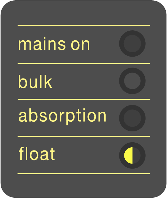 | Scaling factor | 0 | 0 - 9 |
2 | 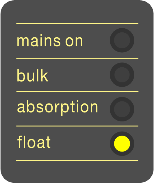 | Generator current (A) | 16 | 0 - 198 |
3 | 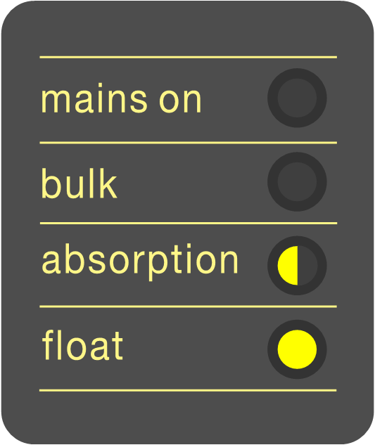 | Upper AC current limit for AC1 input (A) | 254 | 0 - 254 |
4 | 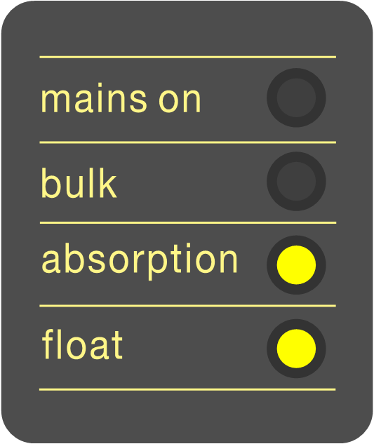 | Upper AC current limit for AC2 input (A) | 254 | 0 - 254 |
5 | 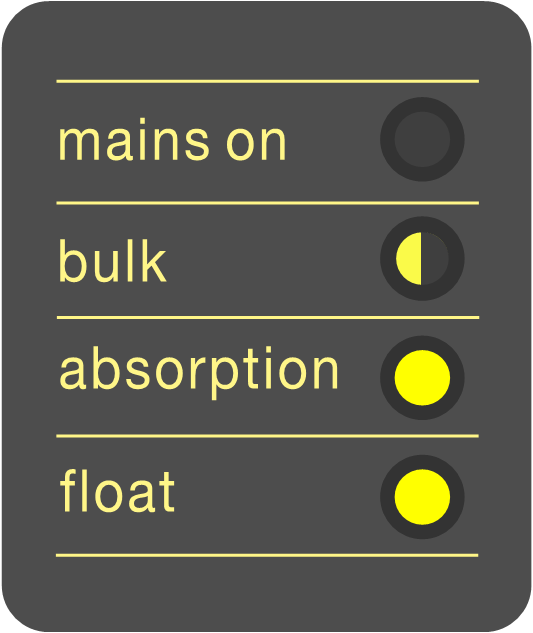 | Upper AC current limit for AC3 input (A) | 254 | 0 - 254 |
6 | 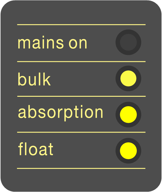 | Upper AC current limit for AC4 input (A) | 254 | 0 - 254 |
 = LED is off,
  = LED is blinking,
  = LED is on