7. Operation
The control panel controls and monitors the inverter/charger system.
The control panel is active as soon as the inverter/charger system is switched on.
ID | Description |
|---|---|
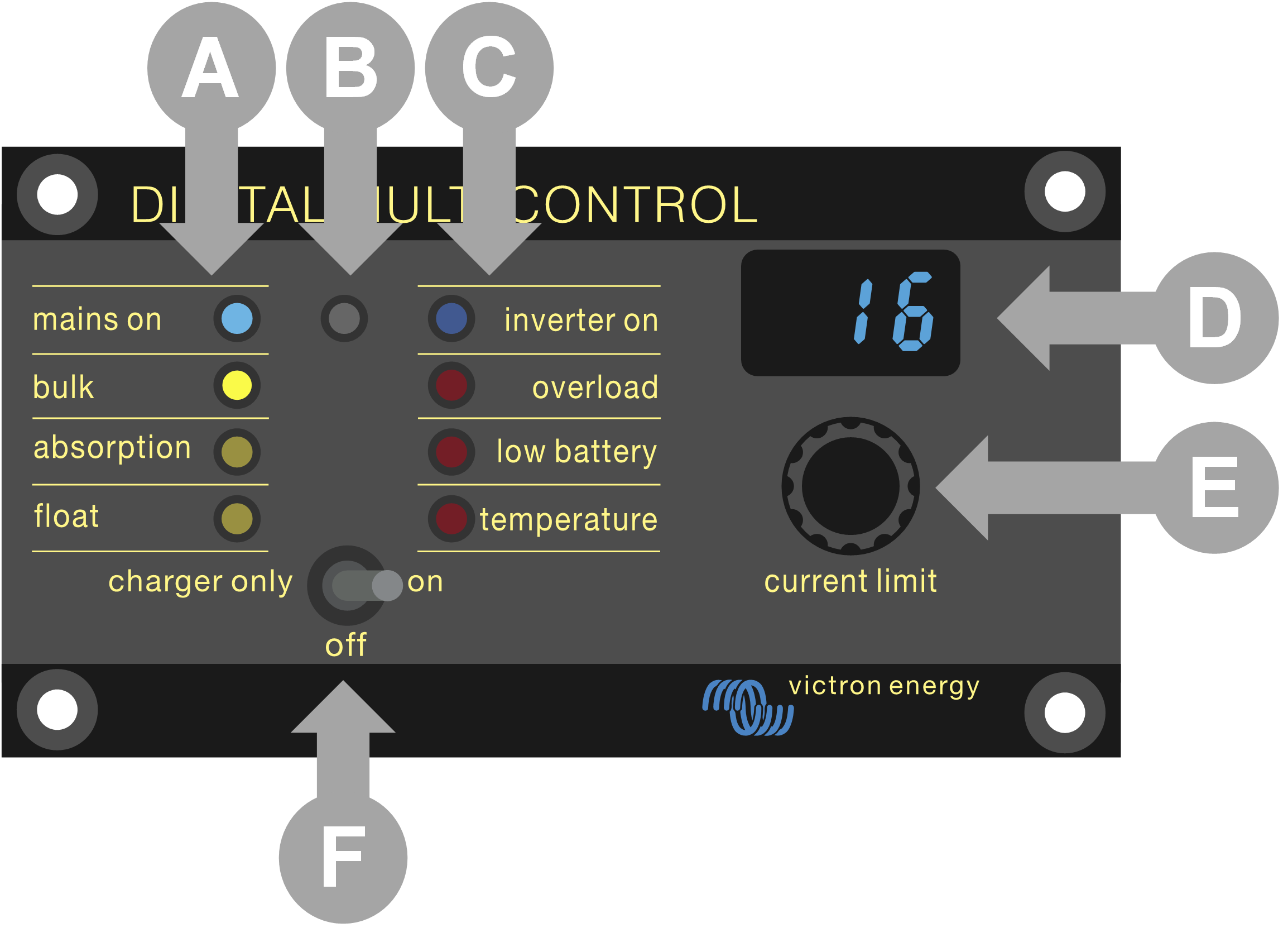
A | Charger LEDs: mains on, bulk, absorption and float. |
B | Light sensor, used to automatically dim the LED brightness. |
C | Inverter LEDs: inverter on, overload, low battery and temperature. |
D | Display, showing the AC input current limit, AC source or VE.Bus errors. |
E | AC current limiter knob, use to adjust the AC input current limit. |
F | On / off / charger-only switch, use to turn the inverter/charger on, off or to charger-only mode. |
7.1. Turning the system on and off
Use the switch on the control panel to switch the system on, off or to charger-only operation.
7.2. Adjusting AC input current limit
Adjust the AC current limit using the control knob. The display shows the set limit, and in case of multiple AC inputs, the display also shows the active AC input source (AC2, AC3, AC4).
When PowerAssist is enabled in the inverter/charger system, a minimum AC input current limit value applies. See the table below. If set below this value, the inverter/charger stops charging, opens its internal transfer relay, disconnects from the AC supply and starts inverting.
Current limits adjust in 0.5A steps under 10A, and 1A steps over 10A. For instance, an 11.1A limit rounds to 12A.
The control panel prevents setting a limit below the inverter/charger system's minimum AC current. If the AC input current limit needs to be set to 0A (below the inverter/charger's limit), quickly turn the knob anticlockwise. The control panel display shows 0.0, and the inverter/charger(s) will stop charging and start inverting. Turn clockwise to revert back to the minimum AC current limit.
AC voltage (V) rating | Power (VA) rating | Minimum configurable AC current limit (A) |
|---|---|---|
120 | 2000 | 5.5 - 8.4 * |
3000 | 7.5 - 9.5 * | |
5000 | 13.0 - 13.4 * | |
10000 | 18.5 | |
230 | 500 - 1200 | 2.4 |
1600 | 2.4 - 2.8 * | |
2000 | 2.4 - 4.5 * | |
3000 | 3.0 - 4.5 * | |
5000 | 3.9 - 6.4 * | |
8000 | 7.6 - 10.5 * | |
10000 | 8.6 - 10.5 * | |
15000 | 10.1 - 14.5 * |
*) The exact value depends on the inverter/charger model. Refer to the "Minimum input current limits" spreadsheet, located in the "VE.Bus (Multies, Inverters and Quattros)" folder in the firmware section on the Victron Professional website.
7.3. LED brightness
For your comfort, the light sensor auto-adjusts LED brightness. As ambient light drops the LEDs dim to a more comfortable level and save power.