Peter Kennedy is an experienced Victron Dealer/Installer specialising in Marine applications. His company website PKYS carries a useful guide to installing a MultiPlus Inverter.
In it Peter adds a whole world of information to the Victron Energy MultiPlus installation manual. He discusses the practicalities of installing a MultiPlus Inverter in compliance with the standards of the American Boat and Yacht Council (ABYC); he explains what we’re looking at when we remove the front panel; and he explains the connection-options to other devices.
We are grateful to him for allowing us to reproduce his advice here:
Introduction
This article details the installation of the US Version of the Multiplus 12/3000. This is a 12 Volt DC 120 Volt AC inverter/charger. The official title is MultiPlus 12/3000/120-50 120V VE.Bus and the title indicates that the inverter output is 3000 VA, the charger is rated for 120 Amps and it has a 50 Amp transfer switch. This blog post details unpacking, mounting and wiring your new MultiPlus.
Quick Install Sheet
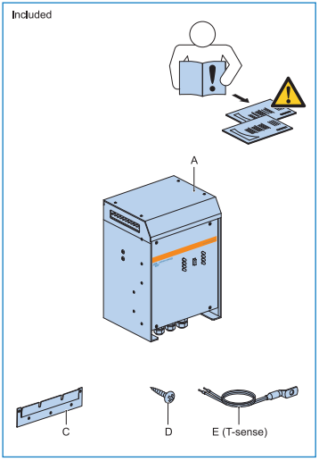
If you have built an Ikea bookcase you will instantly recognize the style of the Quick Install Sheet. It is showing you what is in the box, what isn’t in the box, how to mount the unit and how to wire it up. It’s not that easy to follow, so I am going to interpret it in conjunction with the other more detailed manuals, which lack drawings, and I will maybe throw in a photo or two for good measure.
What’s included in the box?
Multi Plus
Wall mounting plate
Fasteners
Temperature sensor,
User manuals
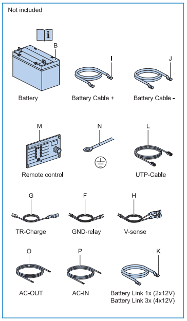
What’s not included?
Battery
Battery cable
Battery switch
Fuse and fuseholder
Remote control panel
Cable to connect remote control panel
AC input wires
AC output wires
Grounding cable
Voltage sense cable
Other optional cables
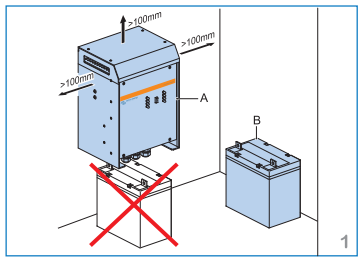
Don’t install an inverter above the batteries
This is an ABYC requirement. Lead acid batteries give off corrosive gases that can destroy equipment directly above them, even sealed batteries can vent corrosive gases on occasion. The following diagram is showing you that the MultiPlus needs some space around it for ventilation. The Service Manual gives you more details about the mounting including the following: “The product must be installed in a dry and well-ventilated area, as close as possible to the batteries. There should be a clear space of at least 10cm around the appliance for cooling.”; and also: “The device can be fitted either horizontally or vertically. For optimal cooling, vertical fitting is preferred.” There is more mounting information in the Service manual.
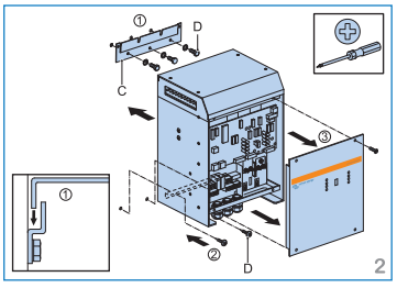
Mounting is easy
You screw the mounting bracket to the wall. Hang the MultiPlus on the bracket. Pop two screws in the bottom to stop it jumping off. If you are installing it horizontally the same applies.
Connecting the small cables
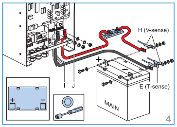
This next diagram is a bit confusing because the current model of the MultiPlus doesn’t look like the drawing. At this point it would be helpful to have an actual photograph to see what it really looks like. As we go along I will explain what all the connections are.
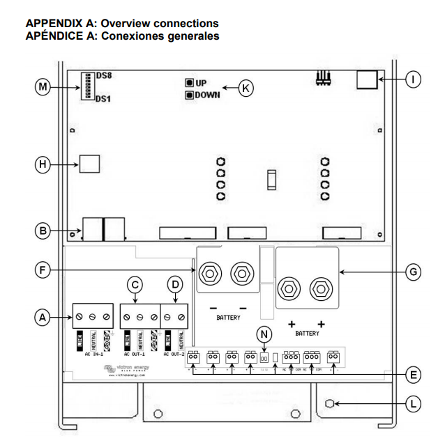
In the service manual Appendix A gives a drawing to help identify the components and connections.
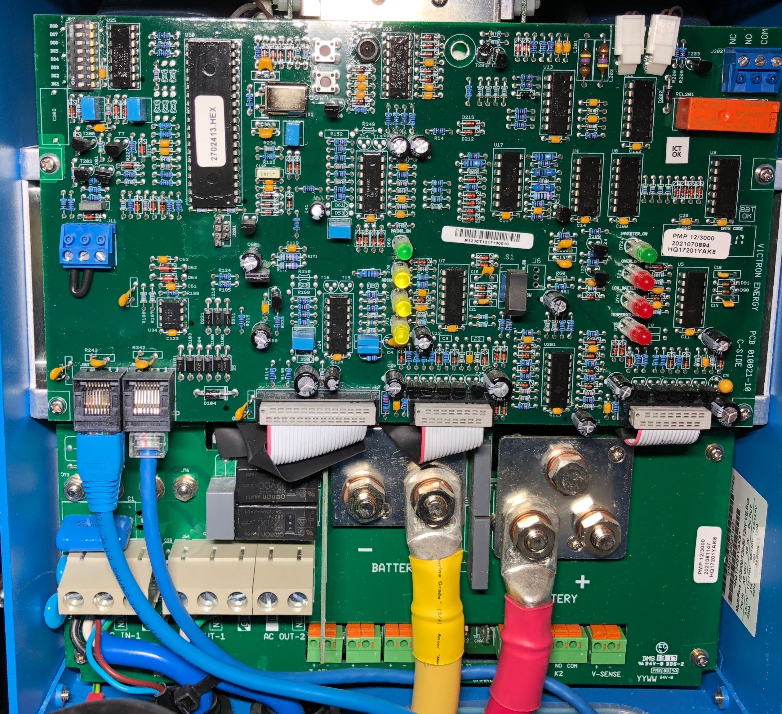
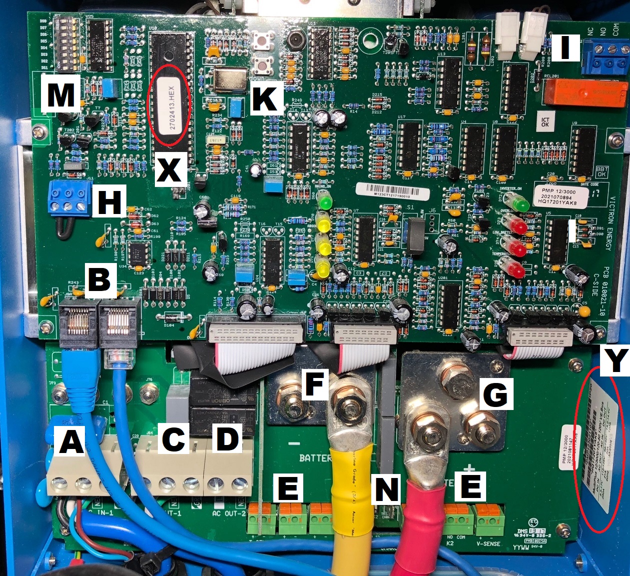
Here’s a photograph of the same view:
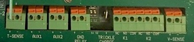
The connections for the small wires are all in the set of green terminals in the very bottom of the photo. They are all labelled as E in the diagram above. The image below shows what they look like without the wires in the way:
The first pair labelled T-Sense are for a temperature sensor. The sensor mounts on the battery negative terminal. The wires are labelled +ive for red and -ive for black.
The Aux1 and Aux2 are input terminals and are programmable. We will discuss these when we get to the programming section in a future blog post, typical uses include remote control from the Battery Management System (BMS) of a Lithium Battery where they could be programmed as “allow to charge” and “allow to discharge”
The Ground Relay terminal is used if you are installing an Autotransformer, see Autotransformer Instructions for further details
The trickle charger terminal can be used for charging an auxiliary battery such as a starting battery. This is just the positive connection. The battery negatives must be common to each other. Max output is 4 Amps
K1 and K2 terminals are relay contacts which are programmable and can be used, for example, to automatically start a generator
The V Sense wire can be connected to the battery to give a more accurate reading of the battery avoiding voltage drop in the battery main cables. Installing a voltage sense wire is not required but it does give improved performance because the sensor reads the actual battery voltage and can compensate when charging for up to a one volt drop in the cables. There is a +ive and -ive connection that goes to battery positive and negative. (A fuse is required)
Main Battery Cables
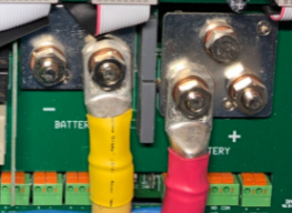
The next panel shows the main battery cable connections.
In the diagram above they show a single positive and a single negative cable, but if you look at the picture below you can see there are two studs you can connect to for each with the intention that if necessary you can double-up the cables. The diagram above does not show a battery switch but in the ABYC standards this is a requirement. You need to be able to turn this off if there is a problem or if you want to work on the system. The service manual goes into the cable size in some detail.
The service manual suggests using doubled-up 1/0 cables for the main supply and suggests using a 400 Amp fuse for the 12/3000 multiplus. A Class T fuse would be appropriate for this application. The ABYC has quite a bit to say about using doubled-up connectors like this; I have summarized it in the footnotes. According to my reading of the ABYC standard if you were using standard 105°C rated battery cable you would need to use 4/0 AWG cable if you had a 400 amp fuse in the line. The main principal to bear in mind here is that the cables carry a lot of load and the load carrying capacity must match the circuit protection. If doubled-up cables are used the ABYC says each individual cable must be capable of carrying the entire load by itself and they must share a single fuse. The cables need to be as short as possible to reduce voltage drop, the longer they are the greater the cross sectional area needs to be, and the less voltage drop there is the better the performance.
Aux Battery Charger
This next panel shows the charging circuit for an auxiliary battery such as a starting battery. It has a maximum 4 amp output. The drawing shows that the Aux battery and the Main battery must share a common negative. Then the only wire you need for this is the positive wire. The drawing doesn’t show a fuse for this wire but one is required at the battery end. The wire connects to the terminal labelled “trickle charge” in the middle of the set of green terminal strips.
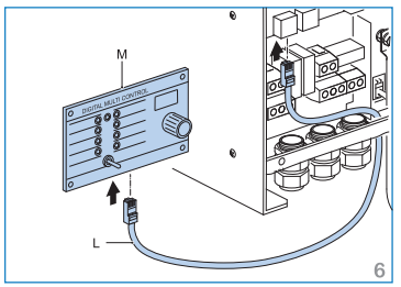
Connecting a remote panel
A remote panel is not included with the MultiPlus but is available separately.
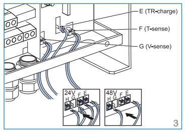
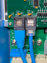
There are two versions, the Digital Multi Control and the Digital Multi Control GX. These are functionally identical but have a slightly different appearance, the GX version is designed to match the appearance of the Color Control GX. The port is called a VE Bus port and the cable needed for this is the RJ45 UTP cable – also sold separately. It plugs into the position labelled “B” in the big drawing above (titled ‘Appendix A’) and in the photo at the end of this article. There are two adjacent sockets and you can plug it into either, they are identical. There are other things you can plug in there too including a parallel cable to connect multiple units or the new VE.Bus Bluetooth Dongle. Here is a photo showing two devices plugged in.
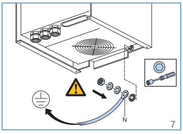
AC Case ground
There is a terminal for connecting an AC Case Ground. I wasn’t able to find any written reference to this in either of the other manuals. The ABYC does have some things to say about case grounds for Inverter/Chargers though.
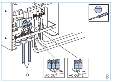
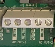
AC Output Connections
The MultiPlus 12/3000 has dual AC Outputs.
AC Output 1 is the main output. It supplies power regardless of whether shore or generator power is available or not and is the output on which the ‘PowerAssist’ feature is available. PowerAssist adds battery power to an AC source (shore or generator for example) when the on-board power demand would otherwise exceed the available current limit. AC Output 2 is only live when the MultiPlus is connected to an external AC source (eg. shore or generator). The thinking here is that by using AC Output 2 for non essential loads like water heaters, you’ll never accidentally drain the batteries if the generator or shore power fails. Each output has terminals for Line, Neutral and Ground. The Ground output is shared between the two outputs. Here is a photo:
AC Output 2 is limited to 32 Amps. The Service manual details the recommended wire sizes based on a 50 Amp shore or generator input, see below. The output wires are sized to add the inverter’s PowerAssist amps to the shore or generator power available. For configurations with less than 50 Amp shore-power/generator power or installations where PowerAssist is disabled it should be possible to reduce the necessary wire size by reference to the ABYC tables.
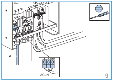
AC Input Connections
The AC input terminals are on the extreme left and comprise a Line, Neutral and Ground terminal. Recommendations for wire size are shown in the table above and are based on a 50 Amp shore or generator supply.
Finishing the Installation
Before you put the panel back on you may want to check your work. Have you got the polarity right for the DC terminals? Reverse polarity on these is a fatal error that will destroy the unit. Are the bolts tight? Have you mixed up your incoming and outgoing AC connections? Are those screws tight? Have you connected all the optional extra devices? There are also a few things you might like to look at before you close the lid so I have annotated the photo below with some notes. For most installations you will want to at least do some basic programming of this device. The most basic programming is done using the dipswitches and that requires the cover to be open. Anything more elaborate should be done using one of the computer interfaces available, such as VE Configure. You might also like to make a note of the model and serial number, and the processor number as these are all things you might need later and it’s a lot easier to write them down in the manual than it is to go and open up the unit again. In the photo below I used the same letter key as in the drawing earlier in the article. Below the photo is a list of what all these items are.
A AC Input connections
B VE.Bus ports for remote panel, parallel configurations etc. (Both ports are identical – you can use either or both.)
C AC Output 1 – this is the primary output
D AC Output 2 – only works on shore power or generator and is limited to 32 Amps
E Optional ports for temp sensor, voltage sensor, programmable options
F DC negative connection (dual terminals available if double cables are used)
G DC positive connection (dual terminals available)
H Connector for remote switch (On, Off, Charger only)
I Programmable relay alarm contact.
K On-Off Push buttons used in conjunction with dipswitches for basic programming
M Dipswitches used for basic programming
N Slide switches. Slide switch 1 is used for the ground relay function if the unit is connected to an autotransformer. Switch 2 is not currently used for anything.
X Main Processor, make a note of the number in case a firmware update is ever needed (hint: take a photo) The first four digits of the processor number must match the first four digits of the firmware file name.
Y Serial number and model number, make a note or take a photo.
All the above is taken from Appendix A of the service manual which has additional information on the functions of each item.
Other versions of this MultiPlus
The 24 volt version of this should be almost identical (24/3000) The “Compact” 12/2000 MultiPlus is a bit different, it only has a single AC output and it has a greatly reduced number of terminals for optional connections.
Quattros
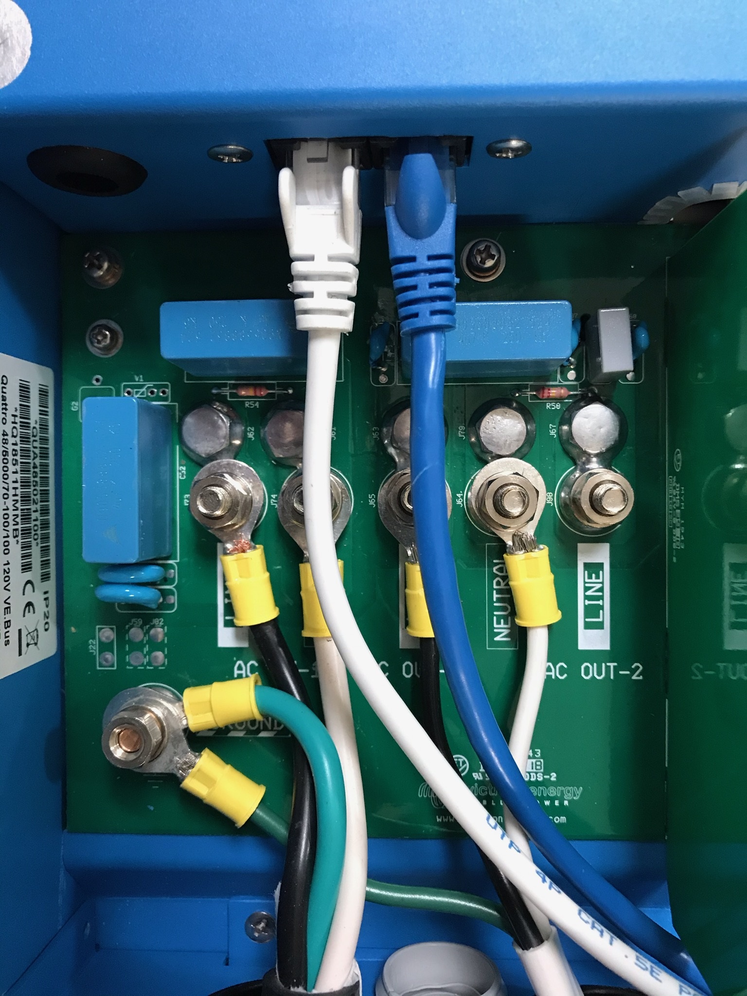
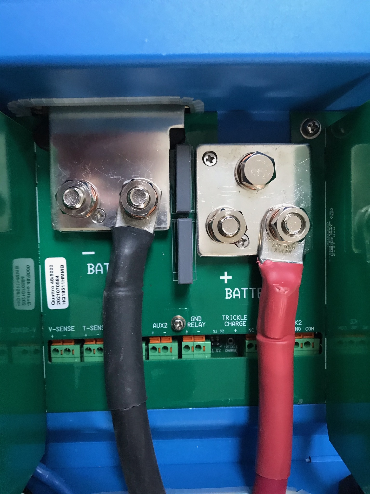
These photos are of a 48 Volt 5000 VA Quattro. You can click on the thumbnail to enlarge the photos. The first one is the AC wiring area and the second is the DC wiring area and all the small connection points.
User manuals
The following manuals are available for the MultiPlus, I’m not sure which ones are in the box:
ABYC 11.6.1.2.1 A battery switch shall be installed in the positive conductor(s) from each battery or battery bank with a CCA rating greater than 800 amperes or 100 Ah if CCA is unavailable.
11.10.1.4 Non-motor Loads – The current rating of the overcurrent protection device shall not exceed the maximum current-carrying capacity of the conductor being protected (see TABLES 6A-B). EXCEPTION: If there is not a standard current rating of the overcurrent protection device equal to 100% of the allowable current for the conductor in TABLES 6A-B, the next larger standard current rating may be used, provided it does not exceed 150% of the current allowed by TABLES 6A-B.
11.14.1.2.8 Paralleling of Conductors – conductors of #10 AWG and larger shall be permitted to be connected in parallel where the ampacity of each individual conductor is sufficient to carry the entire load current shared by the parallel conductors. NOTE: Paralleled conductors may be used to achieve the appropriate voltage drop or wire bend radius with smaller individual cables.
11.14.1.2.8.1 Overcurrent protection of paralleled conductors shall be sized to protect a single conductor.
11.14.1.2.8.2 Paralleled conductors shall be of the same length and gauge.
11.14.1.2.8.3 Paralleled conductors shall be run together in the same cable, bundle, or raceway.
Here is a link to the Ampacity Tables referred to above, in almost all cases we are using battery cable with 105°C insulation. According to the ABYC if you put a 400 amp fuse in the line then you have to use 4/0 cable. Two times 2/0, which has the same cross sectional area, doesn’t comply because the individual cable is not capable of carrying 400 Amps. I called them up at the ABYC to get some clarification on circuit protection for doubled-up cables. You can use either one fuse or two if you have double cables, but in either case the fuse needs to be sized for what a single cable can carry.
From A-31 BATTERY CHARGERS AND INVERTERS
MOUNTING
31.5.5.6 To avoid corrosive fumes, battery chargers, inverters and inverter/chargers shall not be installed directly over batteries.
31.6.5 DC GROUNDING CONNECTIONS
31.6.5.1 The DC grounding conductor shall,
31.6.5.1.1 be connected from the metallic case or chassis, to the engine negative terminal or its bus, and
31.6.5.1.2 shall be of an ampacity equal to that of the DC positive conductor.
EXCEPTION: The DC grounding conductor may be one size smaller than the minimum size conductor required for the DC current carrying conductors.


