3. Installation
3.1. What's in the box?
The following items are in the box:
1x VE.Bus BMS V2
1x Mains detector
1x 0.3m RJ45 UTP cable
Piece of Velcro adhesive hook and loop tape
Note that the DC power cable to power the BMS is not included. Use any 1-wire cable with at least 0.75mm2 (AWG 16) and a 1A inline fuse.
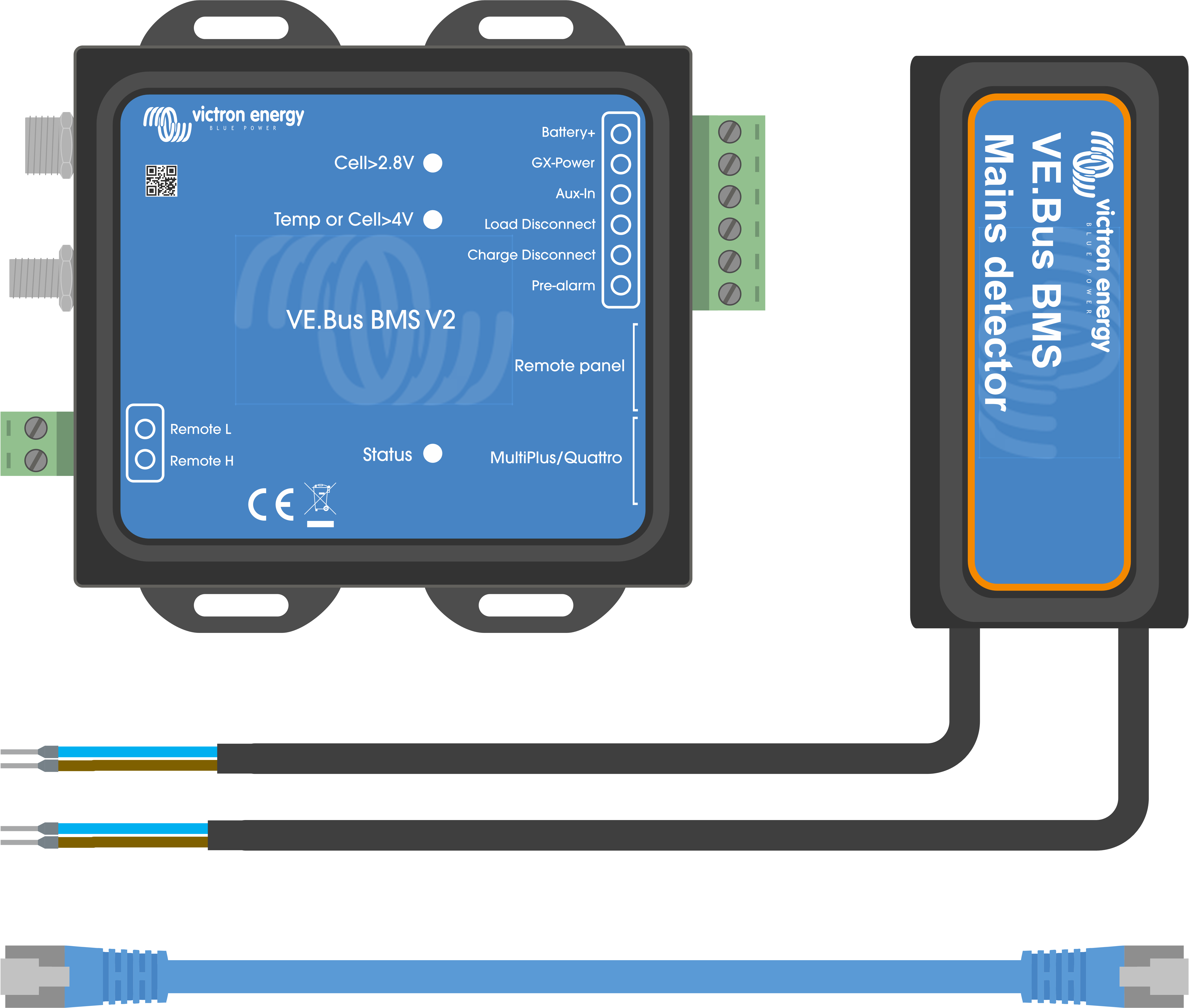 |
What's in the box
3.2. Basic installation
Connect the battery BMS cables to the BMS. For multiple batteries, see the Battery BMS cable connections chapter. Be sure to read and follow the installation instructions in the Lithium Battery Smart manual.
Connect the inverter/charger or inverter positive and negative cables to the battery. Make sure it has been updated to the most recent firmware version. For more information, see the Minimal VE.Bus firmware chapter.
Connect the battery positive via the red power cable with the fuse to the BMS "Battery+" terminal.
Connect the VE.Bus port of the Inverter/charger or inverter to the "MultiPlus/Quattro" port of the BMS using the included RJ45 cable.
In case of a new style MultiPlus 12/1600/70, new style MultiPlus 12/2000/80, MultiPlus-II or Quattro-II, don't install the mains detector. For more information, see the Mains detector chapter.
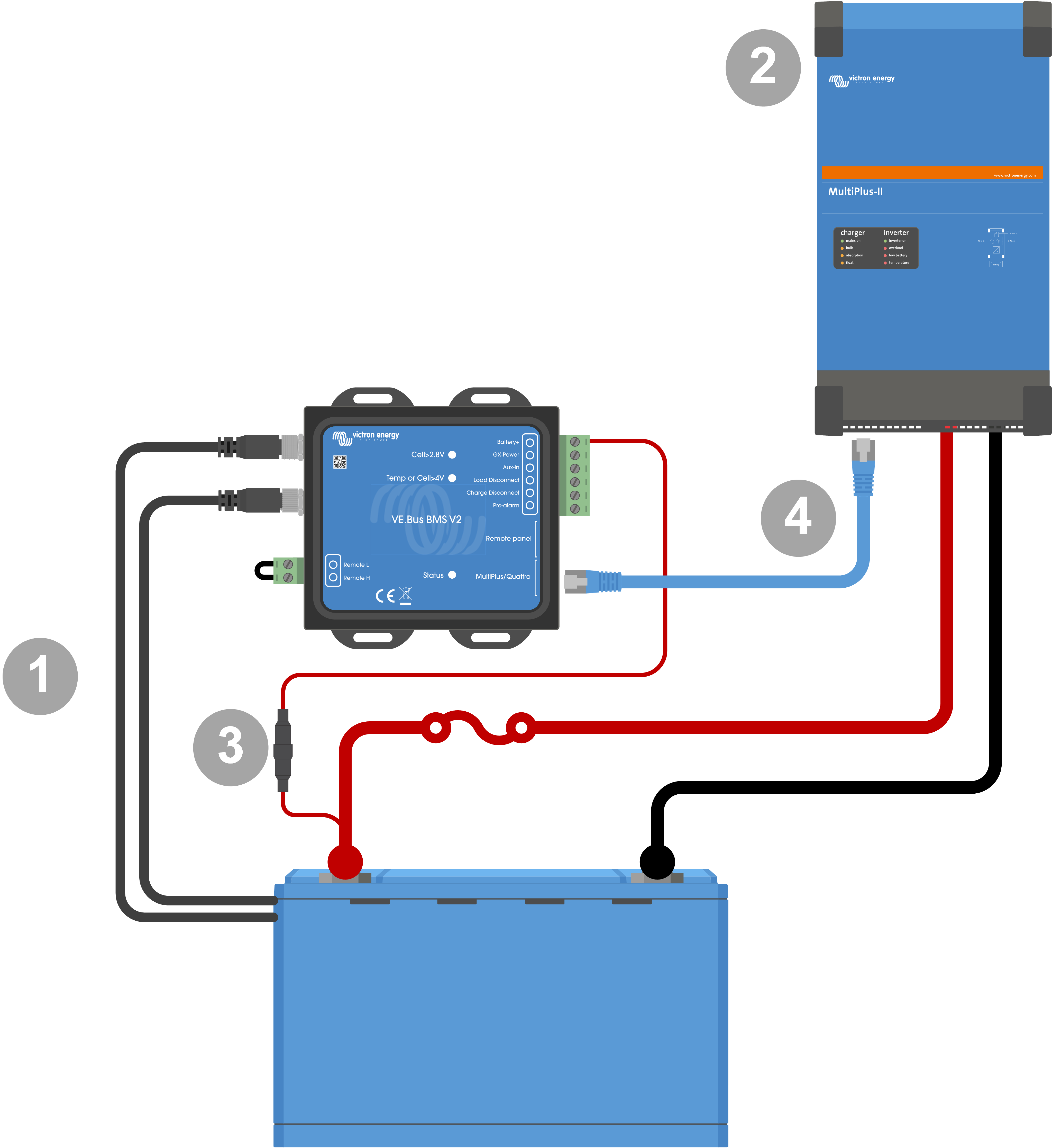
Basic BMS connections
Notice
Note that the BMS does not have a battery negative connection. This is because the BMS obtains battery negative from the VE.Bus. As such, the BMS cannot be used without a VE.Bus Inverter/charger or a VE.Bus inverter.
3.2.1. Minimal VE.Bus firmware
Warning
Incompatibility Warning: Inverter/chargers or inverters with the small processors labeled 19XXXXX or 20XXXXX are not supported. These can be identified by the first two digits on the microprocessor label. For such devices, use the VE.Bus BMS instead of VE.Bus BMS V2.
Important: Firmware requirements before connecting the BMS
Update VE.Bus firmware: Ensure that all inverter/chargers or inverters used in the system have their VE.Bus firmware updated to version xxxx489 or higher.
Firmware between xxxx415 and xxxx489: If the firmware is between xxxx415 and xxxx489, you must install either the VE.Bus BMS or ESS assistant on the inverter/charger.
Firmware below xxxx415: Devices with firmware versions below xxxx415 will trigger a VE.Bus error 15 (VE.Bus combination error), indicating that the VE.Bus products or firmware versions are incompatible. If the firmware cannot be updated to version xxxx415 or higher, the VE.Bus BMS V2 cannot be used.
3.2.2. Battery BMS cable connections
In the case of several batteries in parallel and/or series configuration, the BMS cables should be connected in series (daisy-chained), and the first and last BMS cable should be connected to the BMS.
If the BMS cables are too short, they can be extended with extension cables, the M8 circular connector Male/Female 3 pole cables.
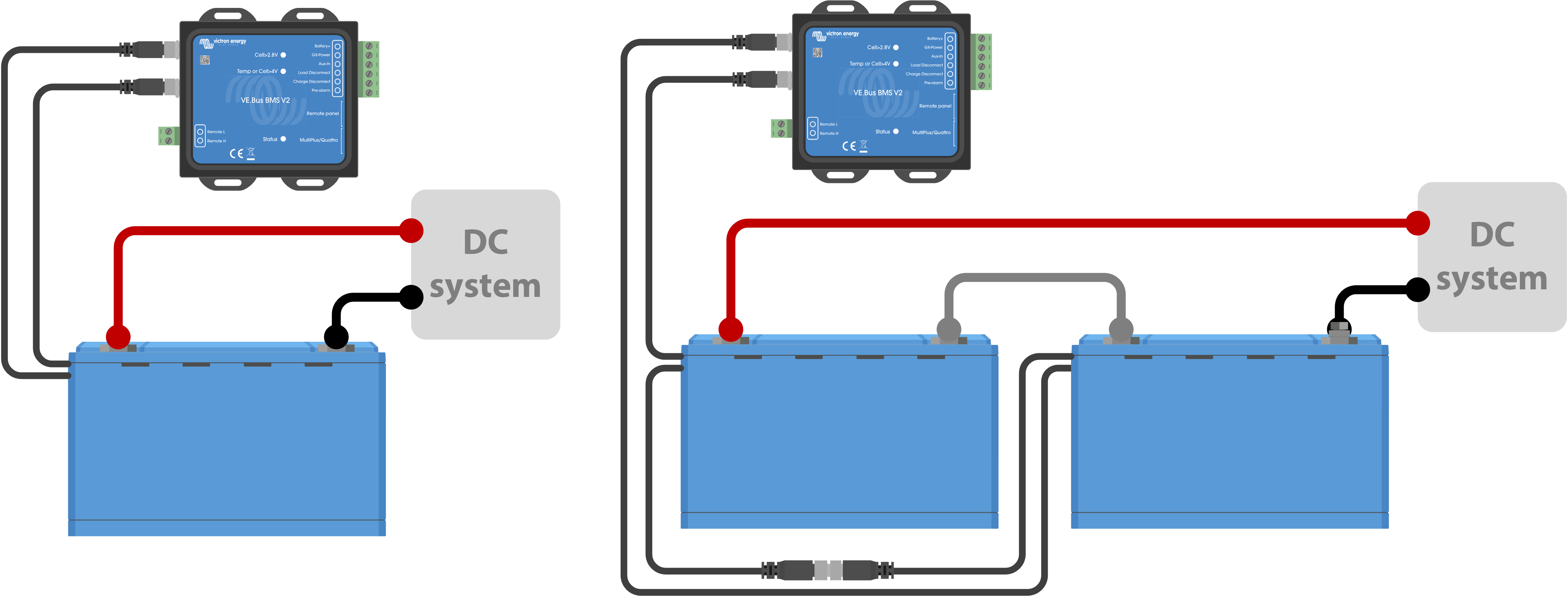
Left: Connecting a single battery. Right: connecting multiple batteries.
3.2.3. Mains detector
Notice
The mains detector is not required for the new style MultiPlus 12/1600/70 and MultiPlus 12/2000/80, MultiPlus-II, Quattro-II and inverter models. In this case, these chapters can be skipped, and the mains detector should be disposed of.
The purpose of the mains detector is to restart the inverter/charger when the AC supply becomes available in case the BMS has shut down the inverter/charger due to low cell voltage (so that it can recharge the battery).
In systems consisting of several units configured for parallel, three-phase, or split-phase operation, the mains detector should be wired in the master or leader unit only.
In the case of a MultiPlus, only use one AC wire pair, and in the case of a Quattro, use both wire pairs.
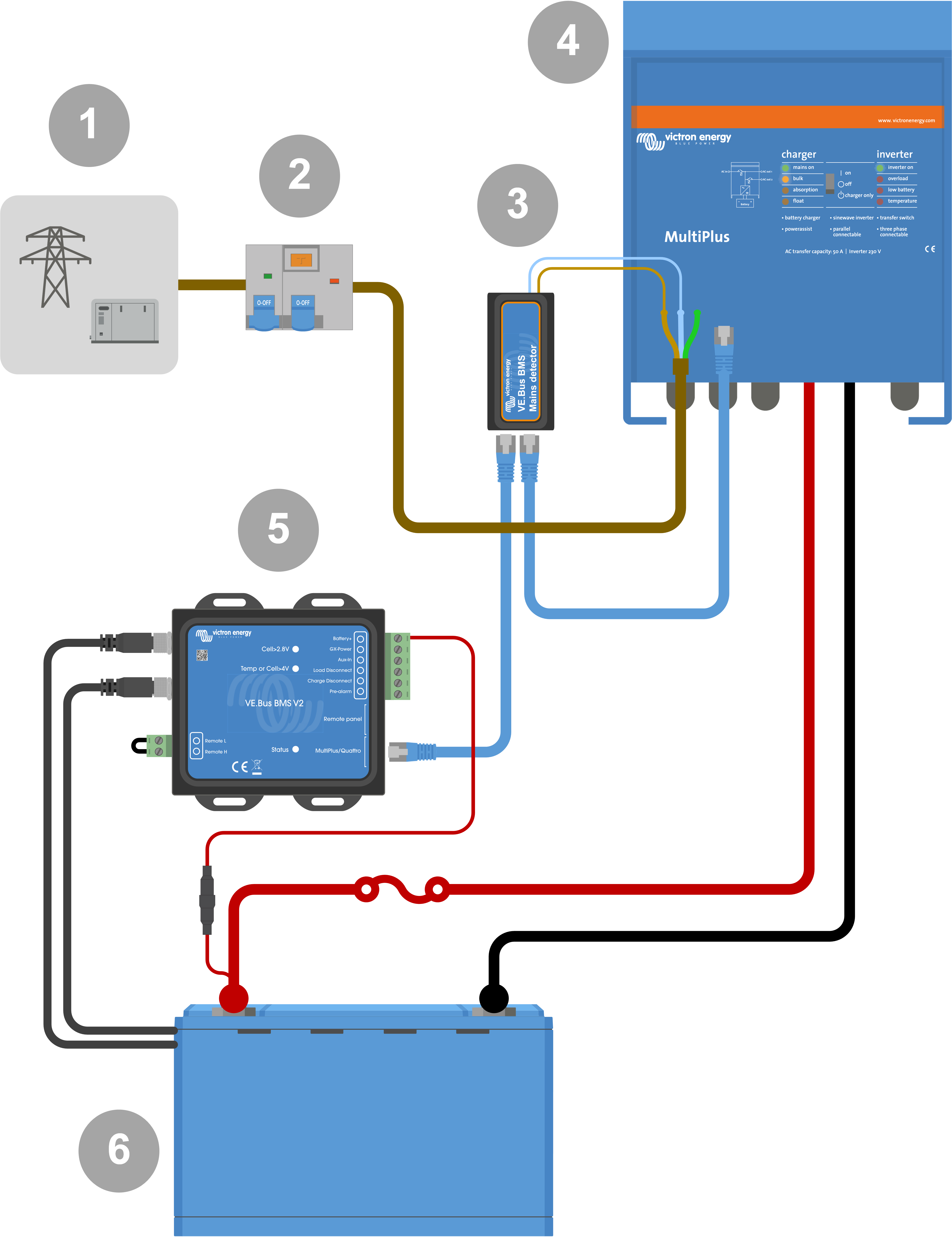 |
AC detector wiring example.
# | Description |
|---|---|
1 | AC grid or generator |
2 | AC circuit breaker and RCD |
3 | Mains detector |
4 | Inverter/charger |
5 | VE.Bus BMS V2 |
6 | Lithium Battery Smart |
3.3. Controlling DC loads and chargers
3.3.1. DC load control
DC loads with remote on/off terminals:
DC loads must be switched off or disconnected to prevent cell undervoltage. The Load disconnect output of the BMS can be used for this purpose. The Load disconnect output is normally high (= battery voltage). It becomes free-floating (= open circuit) in case of an impending cell undervoltage (no internal pull down to limit residual current consumption in case of low cell voltage).
DC loads with a remote on/off terminal that switches the load on when the terminal is pulled high (to battery plus) and switches it off when the terminal is left free-floating, can be controlled directly with the BMS Load disconnect output.
DC loads with a remote on/off terminal that switches the load on when the terminal is pulled low (to battery minus) and switches it off when the terminal is left free-floating, can be controlled with the BMS Load disconnect output via an Inverting remote on/off cable.
Notice
Note: please check the residual current of the load when in the off state. After low cell voltage shutdown, a capacity reserve of approximately 1Ah per 100Ah battery capacity is left in the battery. For example, a residual current of 10mA can already damage a 200Ah battery if the system is left in a discharged state for more than eight days.
Disconnecting a DC load via a BatteryProtect:
Use a BatteryProtect for DC loads that do not have a remote on/off terminal or for switching groups of DC loads off.
A BatteryProtect will disconnect the DC load when:
Its input voltage (= battery voltage) has decreased below a preset value.
Its remote on/off H terminal becomes free floating (usually high). This signal is provided by the Load disconnect output (wired to the remote on/off H terminal of the BatteryProtect) of the VE.Bus BMS V2. See the wiring example System with a BatteryProtect and a solar charger.
3.3.2. DC charge control
3.3.3. Controlling inverter/chargers, solar chargers and other battery chargers
In the event of high cell voltage or low temperature, battery charging must be stopped to protect the battery cells. Depending on the system, chargers are either controlled via DVCC or must be controlled via their remote on/off terminals and the Charge disconnect output of the VE.Bus BMS V2.
In systems with a GX device, you must enable DVCC to ensure that the solar chargers and other DVCC-compatible devices only charge when they should. See DVCC operation with VE.Bus BMS V2 for details.
In systems without a GX device, the BMS Charge disconnect output must control the solar charger and other chargers, either via remote on/off, a BatteryProtect or a Cyrix-Li-Charge. See Charger control via Charge disconnect for details.
3.3.4. DVCC operation with VE.Bus BMS V2
DVCC (Distributed Voltage and Current Control) allows a GX device to control compatible devices such as solar chargers, Inverter RS, Multi RS or Multis.
In order for the GX device to control the solar chargers, Inverter RS or Multi RS in a system with a VE.Bus BMS V2, DVCC must be enabled. These chargers are controlled by setting their maximum charge current limit to zero when the VE.Bus BMS V2 requests that charging should stop.
Note that the presence of a VE.Bus BMS V2 does not control the charge voltage of the solar chargers, Inverter RS, Multi RS or a Multi.
In an ESS system, the Multi controls the charging voltage of the solar chargers, Inverter RS and Multi RS using the configuration made with VE.Configure or VictronConnect. In other words: The charge algorythm must be configured in the Multi.
In a non-ESS (off-grid) system, the solar chargers, Inverter RS, Multi RS and Multi follow their own internal charge algorithm. Here, all devices must be set to the appropriate lithium charge algorithm.
AC chargers and smaller Phoenix inverters are not (yet) controlled by the GX device, and therefore you still need to wire signal wiring (via ATC aka Charge disconnect) to control such devices.
3.3.5. Charger control via Charge disconnect
Chargers that are not DVCC compatible or installed in systems without a GX device can be controlled via the VE.Bus BMS V2 Charge disconnect output, provided the chargers have a remote on/off port.
The Charge disconnect output, normally high (equal to battery voltage), must be connected to the H terminal of the charger's remote on/off connector. At high cell voltage or low temperature, the Charge disconnect output becomes free-floating and pulls the charger's remote on/off H terminal low (to battery minus), stopping the charge.
For battery chargers with a remote terminal that activates the charger when the terminal is pulled low (to battery minus) and deactivates when the terminal is left free floating, the Inverting remote on-off cable can be used.
Alternatively, a Cyrix-Li-Charge relay can be used. The Cyrix-Li-Charge relay is a unidirectional combiner that inserts between a battery charger and the lithium battery. It will engage only when charge voltage from a battery charger is present on its charge-side terminal. A control terminal connects to the Charge disconnect output of the BMS.
3.3.6. Charging with an alternator
Alternator charging can be controlled either with a DC-DC charger such as the Orion-Tr Smart, or with a SolidSwitch 104 when controlling an external alternator regulator like the Balmar MC-614.
Both devices are then also controlled by the BMS Charge disconnect output wired to the Orion-Tr Smart or SolidSwitch 104 remote on/off H terminal. See System with an alternator
3.4. Remote on/off terminal
The BMS remote on/off terminal can be used to turn the entire system on and off while the BMS remains connected to battery positive, which keeps the inverter in low power (discharging and charging not allowed) mode even if it is still connected to AC In.
The remote H and L terminals switch the system on when:
Contact is made between the remote H terminal and L terminal, for example, via the wire bridge or a switch.
Contact is made between the remote connector H terminal and battery positive.
Contact is made between the remote connector L terminal and battery negative.
A typical application is switching off the system when a predetermined state of charge (SoC) is reached in a BMV. Its relay then operates the remote on/off terminal of the BMS. Note that at least the wire loop between pins L and H must be plugged in, so that the VE.Bus BMS V2 can switch on.
3.5. GX device
For solar chargers, Inverter RS, Multi RS or Multis to be controlled by the BMS via a GX device, the following requirements should be met:
The GX device Venus OS firmware must be version 2.80 or above.
Installation:
Connect the GX device VE.Bus port to the Remote panel port on the BMS via an RJ45 cable (not included). Note that this is different from the former VE.Bus BMS V1, which allowed only the connection of a Digital Multi Control. The VE.Bus BMS V2 allows to connect a GX device, a VE.Bus Smart dongle or a Digital Multi Control.
Connect the GX device "power +" terminal to the GX-Pow terminal of the BMS and connect the GX device "power -" terminal to the negative terminal of the battery.
Connect the positive wire of an (optional) AC-DC power supply to the AUX-in terminal of the BMS and connect the negative wire to the negative battery terminal. Note that the AC-DC power supply is optional and most likely not needed in off-grid installations such as boats or RVs.
Perform a VE.Bus re-detect system action on the GX device. This action is available in the inverter/charger menu on the GX device.
GX device connections
Functionality of the GX-Pow and Aux-In terminals:
The GX-Pow output supplies GX power from either the battery or from the Aux-In input, whichever voltage is higher.
The GX device is normally powered via the GX-Pow terminal, which in turn is supplied by the Battery+ connection. In the event of a low cell voltage, this battery supply may no longer be available, causing the GX device to shut down.
To maintain GX device operation during such conditions, an optional AC-DC power supply (not supplied by Victron) can be connected to the Aux-In input. If present, this auxiliary source ensures the GX device remains powered as long as the Aux-In voltage is available, for example, enabling remote access and diagnostics via VRM even if the rest of the system is offline.
3.6. Connecting a Digital Multi Control or a VE.Bus Smart dongle
A VE.Bus Smart dongle or Digital Multi Control (DMC) must be connected to the Remote panel port of the BMS. Both have on/off/charger-only control of the inverter/charger. It is also possible to connect the Phoenix Inverter Control panel in case a Phoenix VE.Bus inverter is used.
Note that in systems containing a Digital Multi Control and a GX device or a VE.Bus Smart dongle at the same time, on/off/charger-only control of the inverter/charger is only possible via the Digital Multi Control.
For example, the VE.Bus Smart dongle, Digital Multi Control and the GX device can all be connected simultaneously to the Remote panel port. However, in this scenario, on/off/charger-only control of the inverter/charger via the GX device and VE.Bus dongle is disabled. Since inverter/charger control is disabled, the GX device or VE.Bus Smart dongle can also be connected to the MultiPlus/Quattro port of the BMS for easy wiring.
 |
Left: System with a Digital Multi Control Panel - Right: System with a VE.Bus Smart dongle
# | Description |
|---|---|
1 | Digital Multi Control (or Phoenix Inverter Control in case a Phoenix VE.Bus inverter is used) |
2 | VE.Bus Smart dongle |
3 | MultiPlus-II Inverter/charger |
4 | VE.Bus BMS V2 The VE.Bus Smart dongle needs to measure the battery voltage. Therefore its Battery+ terminal must be connected to the positive battery terminal. Be aware that the VE.Bus Smart dongle will not be turned off by the BMS in case of a low cell warning and will continue to draw current (up to 9mA - see the VE.Bus Smart dongle specifications for details) from the battery. |
5 | Lithium Battery Smart or battery which can consist of multiple batteries to form a 12V, 24V or 48V battery. |