8. Installation
This product contains potentially dangerous voltages. It should only be installed under the supervision of a suitable qualified installer with the appropriate training, and subject to local requirements. Please contact Victron Energy for further information or necessary training
8.1. Location
The product must be installed in a dry and well-ventilated area, as close as possible to the batteries. There should be a clear space of at least 10 cm around the product for cooling.
Warning
Excessively high ambient temperature will result in the following:
Reduced service life.
Reduced charging current.
Reduced peak capacity, or shutdown of the inverter. Never position the appliance directly above the batteries.
This product is suitable for wall mounting. A solid surface, suitable for the weight and dimensions of the product must be available (e.g., concrete, or masonry). For mounting purposes, a hook and two holes are provided at the back of the casing (see appendix G). The device can be fitted either horizontally or vertically. For optimal cooling, vertical fitting is preferred.
Warning
The interior of the product must remain accessible after installation.
Try and keep the distance between the product and the battery to a minimum in order to minimize cable voltage losses.
For safety purposes, this product should be installed in a heat-resistant environment. You should prevent the presence of e.g. chemicals, synthetic components, curtains or other textiles, etc., in the immediate vicinity.
8.2. Connection of battery cables
To utilize the full capacity of the product, batteries with sufficient capacity and battery cables with sufficient cross-section should be used. See table.
MultiPlus-II GX model | Recommended battery capacity (Ah) | Recommended DC fuse | Cable core cross-section 0-5m * | Cable core cress-section 5-10m * |
|---|---|---|---|---|
24/3000/70 GX | 200 - 700 Ah | 300A | 50 mm² | 95 mm² |
*) Recommended cross-section (mm²) per + and - connection terminal | ||||
Remark: Internal resistance is an important factor when working with low-capacity batteries. Please consult your supplier or the relevant sections of our book 'Energy Unlimited', downloadable from our website.
8.3. Battery Connection procedure
Proceed as follows to connect the battery cables:
Warning
Use a torque wrench with insulated box spanner in order to avoid shorting the battery. Avoid shorting the battery cables.
Warning
Specific care and attention must be taken when making the battery connections. Correct polarity must be confirmed with a multimeter before connection. Connecting a battery with incorrect polarity will destroy the device and is not covered by warranty.
Undo the two screws at the bottom of the enclosure and remove the service panel.
Connect the battery cables. First the - cable then the +. Be aware that there may be a spark when making the battery connections.
Tighten the nuts to the prescribed torques for minimal contact resistance.
8.4. Connection of the AC cabling
Warning
This is a safety class I product (supplied with a ground terminal for safety purposes). Its AC input and/or output terminals and/or grounding point on the inside of the product must be provided with an uninterruptible grounding point for safety purposes. see Appendix A.
In a fixed installation, an uninterruptible grounding can be secured by means of the grounding wire of the AC input. Otherwise the casing must be grounded.
This product is provided with a ground relay (relay H, see Appendix B) that automatically connects the Neutral output to the chassis if no external AC supply is available. If an external AC supply is provided, the ground relay H will open before the input safety relay closes. This ensures the correct operation of an earth leakage circuit breaker that is connected to the output.
In a mobile installation (for example, with a shore current plug), interrupting the shore connection will simultaneously disconnect the grounding connection. In that case, the casing must be connected to the chassis (of the vehicle) or to the hull or grounding plate (of the boat). In case of a boat, direct connection to the shore ground is not recommended because of potential galvanic corrosion. The solution to this is using an isolation transformer.
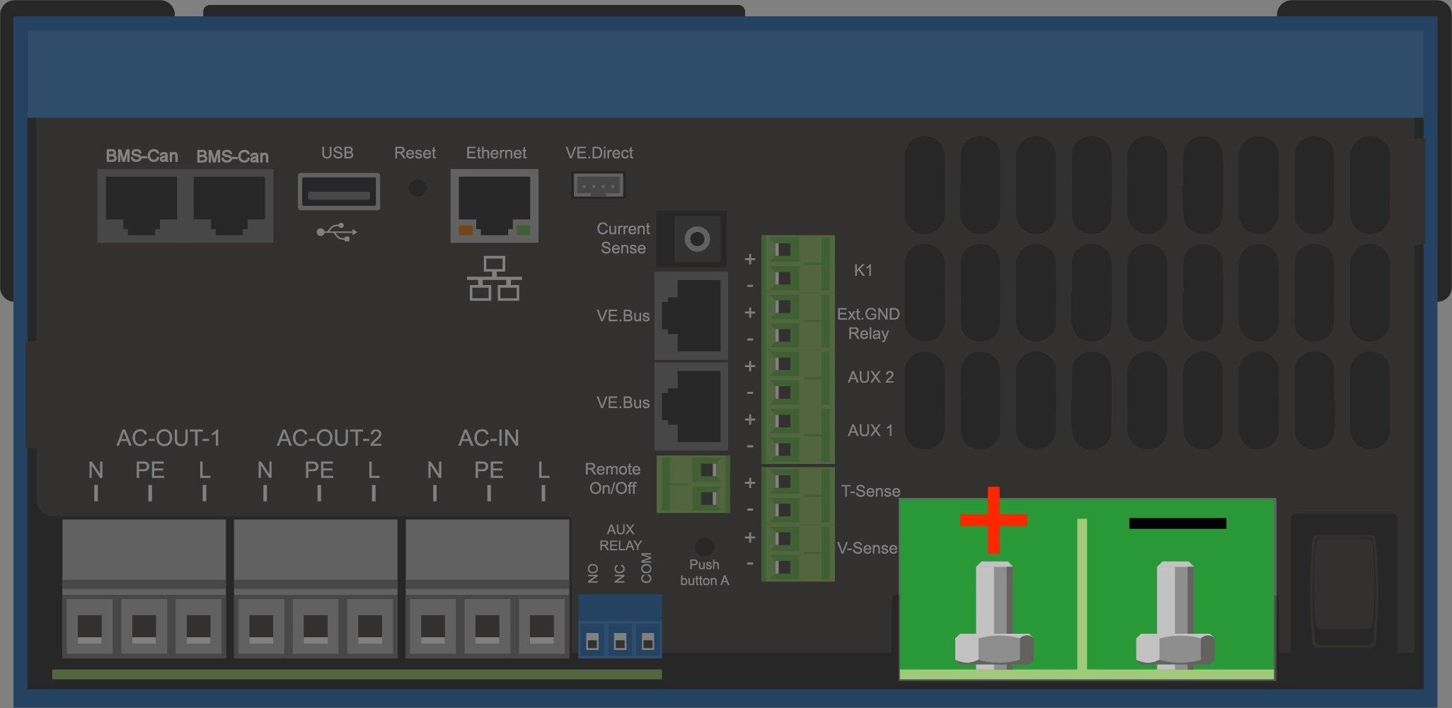
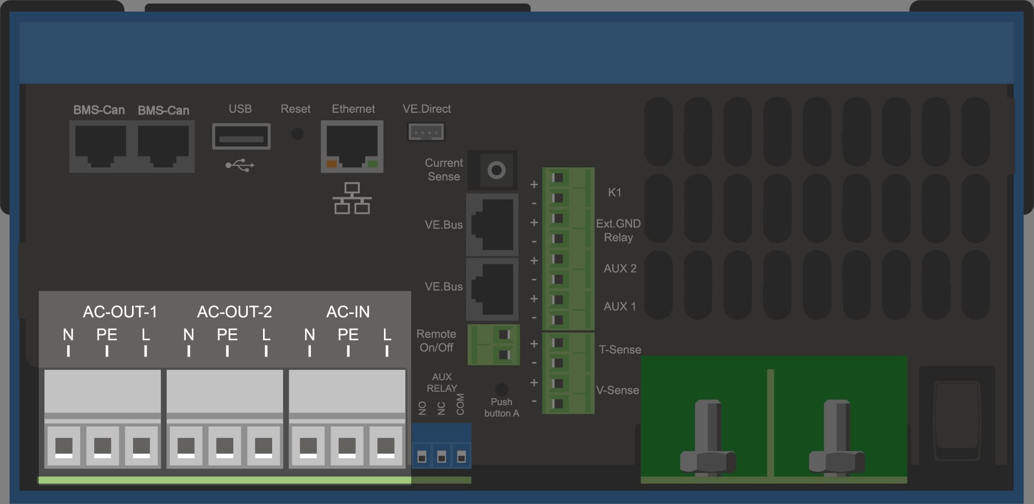
The terminal blocks can be found on the printed circuit board, see Appendix A.
Do not invert neutral and phase when connecting the AC.
The inverter does incorporate a mains frequency isolating transformer. This precludes the possibility of DC current at any AC port. Therefore type A RCD’s can be used.
AC-in The AC input cable can be connected to the terminal block 'AC–in'. From left to right: "N" (neutral), "PE" (earth) and "L" (phase) The AC input must be protected by a fuse or magnetic circuit breaker rated at 32A or less, and cable cross-section must be sized accordingly. If the input AC supply is rated at a lower value, the fuse or magnetic circuit breaker should be down sized accordingly.
AC-out-1 The AC output cable can be connected directly to the terminal block 'AC-out'. From left to right: "N" (neutral), "PE" (earth) and "L" (phase) With its PowerAssist feature the Multi can add up to 3kVA (that is 3000 / 230 = 13A) to the output during periods of peak power requirement. Together with a maximum input current of 32A this means that the output can supply up to 32 + 13 = 45 A. An earth leakage circuit breaker and a fuse or circuit breaker rated to support the expected load must be included in series with the output, and cable cross-section must be sized accordingly.
AC-out-2 A second output is available that disconnects its load in the event of battery operation. On these terminals, equipment is connected that may only operate if AC voltage is available on AC-in-1, e.g. an electric boiler or an air conditioner. The load on AC-out-2 is disconnected immediately when the inverter/charger switches to battery operation. After AC power becomes available on AC-in-1, the load on AC-out-2 will be reconnected with a delay of approximately 2 minutes. This to allow a genset to stabilise
8.5. Optional Connections
A number of optional connections are possible:
8.5.1. Remote Control
The product can be remotely controlled in two ways.
With an external switch (connection terminal M, see Appendix A). Operates only if the switch on the device is set to "on".
With a Digital Multi Control panel (connected to one of the two RJ45 sockets L, see Appendix A). Operates only if the switch on the device is set to "on"
The Digital Multi Control panel has a rotary knob with which the maximum current of the AC input can be set: see PowerControl and PowerAssist.
8.5.2. Programmable relay
The product is equipped with a programmable relay. The relay can be programmed for different applications, for example as a starter relay.
8.5.3. Programmable analog/digital input/output ports
The product is equipped with 2 analog/digital input/output ports.
These ports can be used for several purposes. One application is communication with the BMS of a lithium-ion battery.
8.5.4. Voltage sense (connection terminal J, see Appendix A)
For compensating possible cable losses during charging, two sense wires can be connected with which the voltage directly on the battery or on the positive and negative distribution points can be measured. Use wire with a cross-section of 0,75mm².
During battery charging, the inverter/charger will compensate the voltage drop over the DC cables up to a maximum of 1 Volt (i.e. 1V over the positive connection and 1V over the negative connection). If the voltage drop threatens to become larger than 1V, the charging current is limited in such a way that the voltage drop remains limited to 1V.
8.5.5. Temperature sensor (connection terminal J. see Appendix A)
For temperature-compensated charging, a temperature sensor can be connected. The sensor is isolated and must be fitted to the negative terminal of the battery.
Note
The temperature sensor is not supplied with 48V models.
It can be ordered separately. Order number: ASS000001000
8.5.6. Parallel Connection
It is required to use identical units for three phase and parallel systems. In this case, as only one GX device is allowed per system, if you wish to parallel and/or three phase with this product, you must find the same model MultiPlus-II to pair.
To assist with finding identical units, consider instead using MultiPlus-II for parallel and three phase systems, and an external GX device.
Up to six units can be connected in parallel. When connecting this product with MultiPlus-II in a parallel system, the following requirements must be met:
Warning
It is essential the negative battery terminal between the units is always connected. A fuse or circuit breaker is not allowed on the negative.
All units must be connected to the same battery.
A maximum of six units connected in parallel.
The devices must be identical (aside from GX part) and have the same firmware.
The DC connection cables to the devices must be of equal length and cross-section.
If a positive and a negative DC distribution point is used, the cross-section of the connection between the batteries and the DC distribution point must at least equal the sum of the required cross-sections of the connections between the distribution point and the units.
Always interconnect the negative battery cables before placing the UTP cables.
Place the units close to each other, but allow at least 10cm for ventilation purposes under, above and beside the units.
UTP cables must be connected directly from one unit to the other (and to the remote panel). Connection or splitter boxes are not permitted.
Only one remote control means (panel or switch) can be connected to the system. That means only one GX device. If multiple GX models are to be connected in parallel or three phase, the internal connection between GX card and other components must be disconnected. For this reason it is recommended to use the MultiPlus models without built-in GX for these systems.
8.5.7. Three-phase operation
The product can also be used in 3-phase wye (Y) configuration. To this end, a connection between the devices is made by means of standard RJ45 UTP cables (the same as for parallel operation). The system will require subsequent configuration.
Pre-requisites: see Section Voltage Sense
Note: the product is not suitable for 3-phase delta (Δ) configuration.
When the AS4777.2 grid code has been selected in VEConfigure, only 2 units in parallel per phase are allowed in a three phase system.
For full details on parallel and three-phase configuration always discuss with your Victron distributor first and please see this specific manual:
https://www.victronenergy.com/live/ve.bus:manual_parallel_and_three_phase_systems
8.5.8. Connection to the VRM Portal
Connection of the product to VRM requires an internet connection. This can be made via wifi, or preferably a hardwired ethernet cable to an internet connected router.
The VRM site id is located on a sticker inside the cable connections area of the device.
For more information to set up VRM, refer to the VRM Getting Started Manual.