4. Product Description
The basis of the product is an extremely powerful sine inverter, battery charger and transfer switch in a compact casing. It is suited for use in Marine, Automotive, as well as stationary land-based applications.
4.1. Features applying to all applications
4.1.1. GX LCD display
A backlit 2 x 16 character display screen shows system parameters.
4.1.2. BMS-Can Connections
The BMS-Can connection allows connecting of compatible 500 kbps CAN-bus BMS batteries. VE.Can products as for example Victron MPPT Solar Chargers, or a Lynx Shunt VE.Can are NOT supported.
4.1.3. Ethernet and Wifi
Ethernet and WiFi connections allow for local and remote system monitoring, as well as connection to Victron's free VRM portal for long term system performance information.
4.1.4. Automatic and uninterruptible switching
Houses or buildings with solar panels or a combined micro-scale heating and power plant or other sustainable energy sources have a potential autonomous energy supply which can be used for powering essential equipment (central heating pumps, refrigerators, deep freeze units, Internet connections, etc.) during a power failure. A problem is however that grid connected sustainable energy sources drop out as soon as the grid fails. With the product and batteries, this problem can be solved: the product can replace the grid during a power failure. When the sustainable energy sources produce more power than needed, the product will use the surplus to charge the batteries; in the event of a shortfall, the product will supply additional power from the battery.
4.1.5. Two AC outputs
Besides the usual uninterruptible output (AC-out-1), an auxiliary output (AC-out-2) is available that disconnects its load in the event of battery-only operation. Example: an electric boiler that is allowed to operate only if the AC input is available. There are several applications for AC-out-2.
4.1.6. Three phase capability
The unit can be connected with others and configured for three-phase output. It is possible connect up to 6 sets in parallel in three phases, to a total of 18 units.
4.1.7. PowerControl - maximum use of limited AC power
The product can supply a huge charging current. This implies heavy loading of the AC input. Therefore a maximum current can be set. The product then takes other power users into account, and only uses 'surplus' current for charging purposes.
4.1.8. PowerAssist - extended use of AC input current
This feature takes the principle of PowerControl to a further dimension allowing the product to supplement the capacity of the alternative source. Where peak power is often required only for a limited period, the product will make sure that insufficient AC input power is immediately compensated for by power from the battery. When the load reduces, the spare power is used to recharge the battery.
4.1.9. Programmable
4.1.10. Programmable relay
The product is equipped with a programmable relay. The relay can be programmed for different applications, for example as a starter relay.
4.1.11. External current transformer (option)
External current transformer option to implement PowerControl and PowerAssist with external current sensing
4.1.12. Programmable analog/digital input/output ports
The product is equipped with 2 analog/digital input/output ports.
These ports can be used for several purposes. One application is communication with the allow-to-charge and allow-to-discharge BMS controls of a lithium-ion battery.
See appendix.
4.2. Features specific on-grid and off-grid systems combined with PV
4.2.1. External current transformer (optional)
When used in a grid-parallel topology the internal current transformer cannot measure the current to or from the mains. In this case an external current transformer has to be used. See appendix A. Contact your Victron Distributor for further information about this installation type
4.2.2. Frequency shift
When solar inverters are connected to the AC-output of the product, excess solar energy is used to recharge the batteries. Once the absorption voltage is reached, charge current will reduce and excess energy will be fed back into the mains. If the mains is not available, the product will slightly increase the AC frequency to reduce the output of the solar inverter.
4.2.3. Built-in Battery Monitor
The ideal solution when the product is part of a hybrid system (AC input, inverter/chargers, storage battery, and alternative energy). The built-in battery monitor can be set to open and close the relay:
start at a preset % discharge level
start (with a preset delay) at a preset battery voltage
start (with a preset delay) at a preset load level
stop at a preset battery voltage
stop (with a preset delay) after the bulk charge phase has been completed
stop (with a preset delay) at a preset load level
4.2.4. Autonomous operation when the grid fails
Houses or buildings with solar panels or a combined micro-scale heating and power plant or other sustainable energy sources have a potential autonomous energy supply which can be used for powering essential equipment (central heating pumps, refrigerators, deep freeze units, Internet connections, etc.) during a power failure. A problem is however that grid connected sustainable energy sources drop out as soon as the grid fails. With the product and batteries, this problem can be solved: the product can replace the grid during a power failure. When the sustainable energy sources produce more power than needed, the product will use the surplus to charge the batteries; in the event of a shortfall, the product will supply additional power from the battery.
4.3. Battery charger
4.3.1. Lead-acid batteries
Adaptive 4-stage charge algorithm: bulk – absorption – float – storage
The microprocessor-driven adaptive battery management system can be adjusted for various types of batteries. The adaptive function automatically adapts the charging process to battery use.
The right amount of charge: variable absorption time
In the event of slight battery discharge, absorption is kept short to prevent overcharging and excessive gas formation. After deep discharging, the absorption time is automatically extended in order to fully charge the battery.
Preventing damage due to excessive gassing: the BatterySafe mode
If, in order to quickly charge a battery, a high charge current in combination with a high absorption voltage has been chosen, damage due to excessive gassing will be prevented by automatically limiting the rate of voltage increase once the gassing voltage has been reached.
Less maintenance and aging when the battery is not in use: the Storage mode
The Storage mode kicks in whenever the battery has not been subjected to discharge during 24 hours. In the Storage mode float voltage is reduced to 2,2V/cell to minimise gassing and corrosion of the positive plates. Once a week the voltage is raised back to the absorption level to 'equalize' the battery. This feature prevents stratification of the electrolyte and sulphation, a major cause of early battery failure.
Battery voltage sense: the correct charge voltage
Voltage loss due to cable resistance can be compensated by using the voltage sense facility to measure voltage directly on the DC bus or on the battery terminals.
Battery voltage and temperature compensation
The temperature sensor (supplied with the product) serves to reduce charging voltage when battery temperature rises. This is particularly important for maintenance-free batteries, which could otherwise dry out by overcharging.
4.3.2. Li-ion batteries
Victron LiFePO4 Smart batteries
Lynx Smart BMS - This BMS is recommended when also using a GX device in the system. It is connected via the VE.Can bus interface. Note when using this BMS set the Remote Mode to Remote on/off when commissioning the product in VictronConnect.
SmallBMS - This BMS is connected using the allow to charge, and allow to discharge contacts from the Victron smallBMS to the I/O connection port. Note when using this BMS configure for Remote Mode 2-wire BMS when commissioning the product in VictronConnect.
4.3.3. Other Li-ion batteries
Please see https://www.victronenergy.com/live/battery_compatibility:start
4.3.4. More on batteries and battery charging
Our book 'Energy Unlimited' offers further information on batteries and battery charging, and is available free of charge on our website: https://www.victronenergy.com/support-and-downloads/technical-information.
For more information on adaptive charging, please also refer to the General Technical Information on our website.
Victron provides a comprehensive Online Training program via the https://www.victronenergy.com.au/information/training web portal. Successful completion of this training should be considered essential for system designers and installers, and is recognised with a graduation certificate.
4.4. ESS - Energy Storage Systems: feeding energy back into the grid
When the product is used in a configuration in which it will feed back energy into the grid it is required to enable grid code compliance by selecting the appropriate grid code country setting with the VEConfigure tool.
Once set, a password will be required to disable grid code compliance or change grid code related parameters. Contact your Victron Distributor if you require this password.
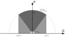
Depending on the grid code there are several reactive Power control modes:
Fixed cos φ
Cos φ as function of P
Fixed Q
Q as function of input voltage
If the local grid code is not supported by the product an external certified interface device should be used to connect the product to the grid.
The product can also be used as a bidirectional inverter operating parallel to the grid, integrated into a customer designed system (PLC or other) that takes care of the control-loop and grid measurement,
Special note regarding NRS-097 (South Africa)
The maximum allowed impedance of the network is 0.28Ω + j0.18Ω
The inverter is fulfilling the unbalance requirement in case of multiple single phase units only when a GX device is part of the installation.
Special notes regarding AS 4777.2 (Australia/New Zealand)
Certification and CEC approval for off-grid use does NOT imply approval for grid-interactive installations. Additional certification to IEC 62109.2 and AS 4777.2.2015 are required before grid-interactive systems can be implemented. Please check the Clean Energy Council website for current approvals.
DRM – Demand Response Mode When the AS4777.2 grid code has been selected in VEConfigure, DRM 0 functionality is available on port AUX1 (see appendix A. To enable grid connection, a resistance of between 5kOhm and 16kOhm must be present between the terminals of port AUX1 (marked + and - ). The product will disconnect from the grid in case of an open circuit or a short circuit between the terminals of port AUX1. The maximum voltage that may be present between the terminals of port AUX1 is 5V. Alternatively, if DRM 0 is not required, this functionality can be disabled with VEConfigure.