3. Installation
3.1. Unpacking and Handling the Battery
Handle the battery with care during unpacking. Batteries are heavy; do not lift the battery by its terminals. Use the carry handles located on both sides. The weight is specified in the Battery Specification.
Before installation, familiarise yourself with the battery layout. The main terminals on the top are marked with “+” (positive) and “–” (negative) to ensure correct polarity.
3.2. Download and Install VictronConnect
Download the VictronConnect app for Android, iOS or macOS from their respective app stores. For more information about the app, see the VictronConnect product page.
3.3. Updating Battery Firmware
Updating the firmware via VictronConnect
The battery firmware can be updated via the VictronConnect app.
Ensure that the latest version of VictronConnect is installed, as this provides access to the most recent firmware.
A new battery is charged to a maximum of 30 % SoC. Fully charge the battery before performing a firmware update.
On first connection, the app may prompt to update the battery firmware. If prompted, allow the update to complete.
Before updating, refer to the firmware update chapter in the VictronConnect manual for detailed instructions.
General notes on firmware updates
Newer isn’t always better – only update if necessary.
If it works, don’t break it – avoid unnecessary updates.
Read the changelog first – available on Victron Professional.
Use this feature with care. Our main advice is not to update a running system unless problems occur or before the first startup.
Notes on updating the Lithium SuperPack NG battery firmware
The firmware update does not cause a full system shutdown.
During the update, the Charge disconnect output opens, preventing battery charging.
If the update fails, the Load disconnect output will open after 120 seconds as a safety measure, allowing time to retry the update.
During a firmware update, the Bluetooth and Error LEDs blink simultaneously, indicating that the update is in progress.
3.4. Mounting the Battery
Observe the following requirements when mounting the battery:
The battery may be installed upright or on its long side.
Do not install the battery upside down.
The battery has an IP65 rating, providing protection against dust ingress and water jets. It can be installed in outdoor or semi-protected environments, but should not be exposed to direct sunlight, heavy rain, or other weather conditions.
Use suitable handling equipment when moving the battery.
Mount securely to prevent movement. In vehicles, use the supplied mounting brackets to reduce the risk of the battery becoming a projectile during an accident.
Allow at least 10 mm clearance on all sides to ensure adequate ventilation during charging and discharging.
 Caution: An unsecured battery can become a projectile in the event of a collision or sudden stop, causing damage or injury. Always use appropriate mounting brackets.
3.5. Electrical Installation
DC wiring
Use battery cables with a cross-sectional area suitable for the maximum expected current in the system.
Appropriately sized cables minimise voltage drop and heat generation. Keep cable lengths equal when connecting multiple batteries in parallel.
For most installations, the voltage drop should not exceed 2 % of the nominal system voltage.
The wire cross-sectional area for the EFS signal wire should be at least 0,75 mm2.
All DC wiring must comply with applicable system design guidelines and local electrical installation regulations.
Fusing
Batteries are capable of delivering very high currents; therefore, all electrical connections to the battery must be fused.
For the main battery terminal connection, use an MRBF-type or T-type fuse with an interrupt rating (IR) of at least 10 kA.
For the EFS signal wire, use a 315 mA fast-acting fuse, DC-rated ≥ 32 V (5×20 mm type).
Install a suitably rated DC fuse as close as possible to the positive battery terminal.
Install all fuses as close as possible to the positive battery terminal. Ensure that the selected fuse ratings comply with the system design guidelines and local electrical regulations.
Terminal connections
| 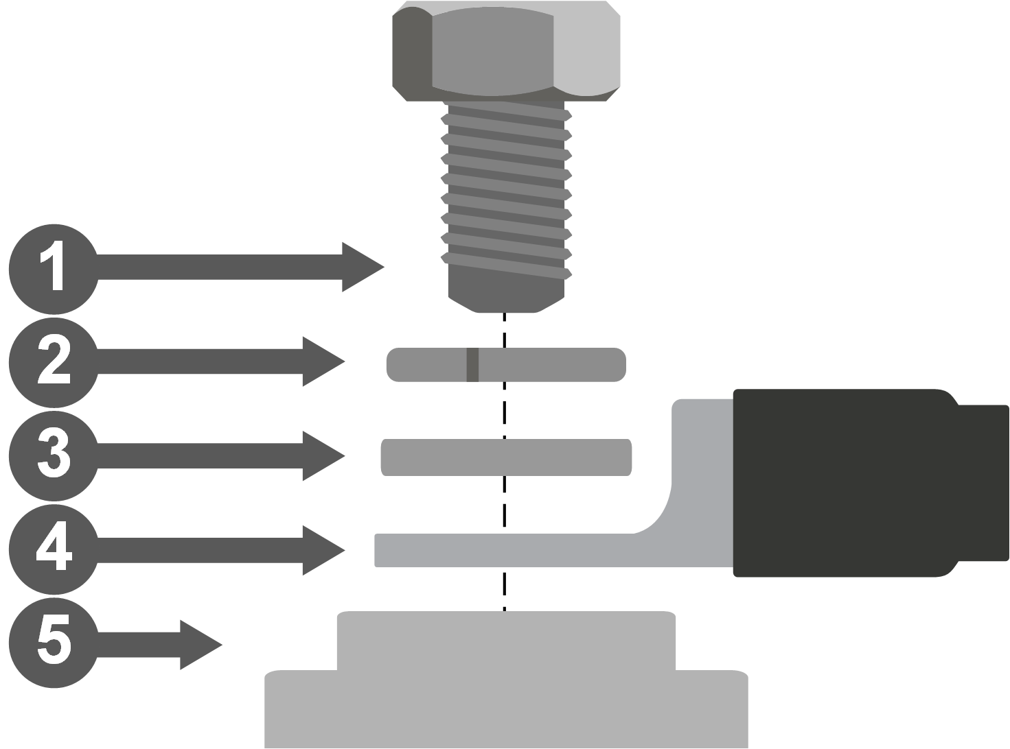 |
Important
Ensure all electrical connections are correctly installed and tightened to the specified torque. Loose or high-resistance connections can cause excessive heat build-up, increasing the risk of damage or fire. Always inspect connections during installation and as part of regular maintenance.
Connection sequence
Connect the positive (+) cable first.
Connect the negative (-) cable last.
When disconnecting, reverse the order.
Consider connecting the External Feedback Signal (EFS) - see External Feedback Signal (EFS) – Function and Wiring.
Important
Note: This battery incorporates an internal negative switch. In OFF status or during a protection event, the negative terminal may be electronically disconnected.
3.5.1. Connecting multiple batteries in parallel
The number of batteries that can be connected in parallel is limited only by the system power. While a maximum system current applies, there is no limitation on total energy expansion. Capacity can therefore be increased without limit, whereas power expansion is restricted by the maximum system current (refer to the Battery Specification.
|  |
Warning
The total system current drawn from a parallel battery pack must never exceed the maximum interruptible current that a single SuperPack NG can safely interrupt (800 A). The main fuse of the battery pack must therefore not be rated above 800 A.
This ensures that, in the event of a system overcurrent, a cascading protection sequence cannot result in a situation where the final battery E-switch is required to interrupt a fault current beyond its specified capability.
Energy expansion (capacity and autonomy) can be increased by adding batteries in parallel. Power expansion, however, must be realised using multiple independent and redundantly protected battery packs.
3.6. External Feedback Signal (EFS) – Function and Wiring
The SuperPack NG battery features a M12 single-pole connector on the top panel that provides the External Feedback Signal (EFS).
The EFS connector can be associated with two functions:
External Disconnection Signal (EDS)
External Charging Signal (ECS)
Although both functions share the same physical EFS output, their signal behaviour and intended use are different.
General EFS characteristics
During normal operation, the EFS output is free-floating (0 V). When active, it outputs a battery-positive voltage (+Vbatt) referenced to battery negative and can supply up to 250 mA.
Warning
Do not connect the EFS output directly to inductive, capacitive, or high-current loads. When using inductive devices such as relays or buzzers without an internal driver circuit, always fit a flyback diode across the coil (cathode to Vbatt+).
Capacitive loads with large inrush currents should be avoided or suitably limited.
Always use the battery negative as the common reference for external devices connected to the EFS output. If multiple devices are connected, ensure that the total current remains within the output capability.
External Charging Signal (ECS)
ECS can be enabled in the VictronConnect app. When active, the EFS output is continuously high at battery-positive voltage (+Vbatt).
ECS is triggered when the configured Low SoC warning threshold is reached. The signal remains active as long as the SoC is below the threshold or a charging current is detected. Whenever SoC is above the Low SoC threshold and no charging current is detected the ECS is deactivated.
Because ECS provides a steady ON/OFF signal, it can be used directly to:
energise a relay coil,
drive a visual or audible alarm,
control devices with a remote on/off input such as a BatteryProtect, Solar Charger, or Orion XS.
External Disconnection Signal (EDS)
EDS is always enabled and provides an additional layer of system protection. When current flow is detected while ATC (Allow To Charge) or ATD (Allow To Discharge) is inactive, the EFS output generates an alternating square-wave signal.
This condition can only occur in rare fault scenarios, such as a fail-short of electronic switching devices. The internal flags allow detection of such malfunctions and enables timely intervention.
EDS is a diagnostic signal and is not intended to directly drive relays, lamps, or buzzers. When using EDS, external logic or signal conditioning is required to detect the square-wave signal and convert it into a stable control or alarm output.
EFS functional wiring examples (ECS)
Indicator light (visible alarm) An indicator light can be connected to provide a visible alarm during ECS operation. Connect the positive lead of the light to the EFS signal pin and the negative lead to the battery negative terminal. The light illuminates continuously while the ECS signal is active. |  |
Audible alarm An audible alarm, such as a buzzer or speaker, can be connected in the same way. The alarm sounds continuously while the ECS signal is active. |  |
Relay-based control – alarm contact A relay with NO/NC contacts can be driven directly by the ECS signal, as ECS provides a continuous battery-positive output. Connect the relay coil positive terminal to the EFS signal pin and the negative terminal to battery negative. When ECS is active, the relay energises and the contact can be used to switch an external alarm or signalling circuit. |  |
Direct control of a Victron product's remote on/off input The ECS function can be used to control Victron products that provide a remote on/off input. It provides an automatic control signal that can be used to enable or disable external equipment based on the Low SoC threshold. Connect the ECS output (EFS signal pin) to either the remote on/off L or H input of the device, depending on the required control behaviour for the application. Use the battery negative as the common reference (GND). When ECS becomes active, the EFS signal goes high (+Vbatt). This activates or deactivates the device via the selected remote on/off L or H input, depending on the application. When ECS is cleared, the EFS signal returns to 0 V (free-floating) and the device reverts to its default state. Refer to the product manual for the correct Remote on/off wiring and input requirements. |  |
Relay-based control of a charger's remote on/off input A relay with NO/NC contacts can be driven directly by the ECS signal. Connect the relay coil positive terminal to the EFS signal pin and the negative terminal to battery negative. When ECS is active, the relay energises and the contact can be used to control a charger or other device with a remote on/off input. |  |
Battery bank solutions (ECS)
Parallel battery bank – ECS outputs connected in parallel In systems with multiple Lithium SuperPack NG batteries connected in parallel, the EFS outputs of all batteries can also be connected in parallel. This ensures that when any battery triggers its EFS signal, the combined output activates, allowing connected devices or alarms to respond to a protection event from any unit in the system. |  |
Parallel battery bank – ECS relay contacts in series In systems with multiple Lithium SuperPack NG batteries connected in parallel, each battery can use its ECS output to drive its own relay. The relay contacts are connected in series, forming a single control path to the external device (for example, the AUX input of a MultiPlus-II). If any battery activates its ECS signal, its relay opens and interrupts the control circuit, ensuring that the system responds immediately to a protection or warning condition from any battery. |  |
EFS functional wiring example (EDS)
The EDS output provides a square-wave diagnostic signal when an internal fault condition is detected while charging or discharging is not allowed. This signal must be connected to external logic capable of detecting the square wave and converting it into a stable alarm or shutdown signal. The EDS output must not be used to directly drive relays. |  |