3. Installation
3.1. Location of the Inverter RS Smart Solar
 | To ensure a trouble free operation of the Inverter RS Smart Solar, it must be used in locations that meet the following requirements: a) Avoid any contact with water. Do not expose the product to rain or moisture. b) Install the Inverter RS Smart Solar upright and vertical. Ensure 30cm clearance above and below it. c) The Inverter RS Smart Solar must be installed on a non-flammable surface and the construction materials surrounding the installation should also be non-flammable. d) Do not place the unit in direct sunlight. Ambient air temperature should be between -40°C and 60°C (humidity < 95% non-condensing). e) Do not install the Inverter RS Smart Solar in an environment where the air could be contaminated with particulate matter such as soot, dust or salt. For example conductive soot from the exhaust of a diesel generator could be drawn into the unit and cause short circuits inside it. f) Do not install the Inverter RS Smart Solar where flammable or corrosive gases or vapours could come near the installation. g) Do not obstruct the airflow around the Inverter RS Smart Solar. h) If the Inverter RS Smart Solar is installed in an area used for general storage, ensure that no flammable materials such a cardboard boxes are stored close to the installation. Ensure that the end user is aware of these requirements. | |
| This product contains potentially dangerous voltages. It should only be installed under the supervision of a suitable qualified installer with the appropriate training, and subject to local requirements. Please contact Victron Energy for further information or necessary training. | |
| Excessively high ambient temperature will result in the following: · Reduced service life. · Reduced charging current. · Reduced peak capacity, or shutdown of the inverter. Never position the appliance directly above lead-acid batteries. The unit is suitable for wall mounting. For mounting purposes, a hook and two holes are provided at the back of the casing. The device must be fitted vertically for optimal cooling. | |
| For safety purposes, this product should be installed in a heat-resistant environment. You should prevent the presence of e.g. chemicals, synthetic components, curtains or other textiles, etc., in the immediate vicinity. | |
| Never connect batteries directly to the Inverter RS Smart Solar without adequate circuit protection. Always ensure that adequate circuit protection is installed between the batteries and the solar inverter. | |
| Batteries shall have a flammability class of HB or better. | |
| Each system requires a method of disconnecting the AC and DC circuits. If the overcurrent protection device is a circuit breaker, it can also serve as the disconnect switch. If fuses are used, separate disconnect switches are required between the source and the fuses. |
Try and keep the distance between the product and the battery to a minimum in order to minimise cable voltage losses
3.2. MPPT grounding, detection of PV array insulation faults & Earth fault alarm notification
The Inverter RS Smart Solar will test for sufficient resistive isolation between PV+ and GND, and PV- and GND.
In the event of a resistance below the threshold (indicating an earth fault), the inverter shuts down and disables the ac outputs (mppt keeps charging the battery as this has no impact on safety due the isolation to the battery side).
If an audible alarm and/or email notification of this fault is required, then you must also connect a GX device (such as the Cerbo GX). Email notifications require an internet connection to the GX device and a VRM account to be configured.
The positive and negative conductors of the PV array must be isolated from ground.
Ground the frame of the PV array to local requirements. The ground lug on the chassis should be connected to the common earth.
The conductor from the ground lug on the chassis of the unit to earth should have at least the cross-section of the conductors used for the PV array.
When a PV resistance isolation fault is indicated, do not touch any metal parts and immediately contact a suitably qualified technician to inspect the system for faults.
The battery terminals are galvanically isolated from the PV array. This ensures that PV array voltages cannot leak to the battery side of the system in a fault condition.
3.3. Battery and battery lead requirements
In order to utilize the full capacity of the product, batteries with sufficient capacity and battery cables with sufficient cross section should be used. The use of undersized batteries or battery cables will lead to:
Reduction in system efficiency.
Unwanted system alarms or shutdowns.
Permanent damage to system.
See table for MINIMUM battery and cable requirements.
Battery capacity | Lead acid | 200 Ah |
Lithium | 50 Ah | |
Recommended DC fuse | 35 mm2 cable | 125 A |
70 mm2 cable | 200 A | |
Minimum cross section (mm2) per + and - connection terminal | 0 - 2 m | 35 mm 2 |
2 - 5 m | 70 mm 2 |
Warning
Consult battery manufacture recommendations to ensure the batteries can take the total charge current of the system. Decision on battery sizing should be made in consultation with your system designer.
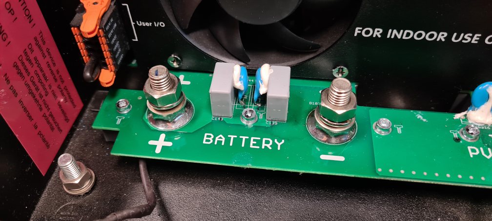
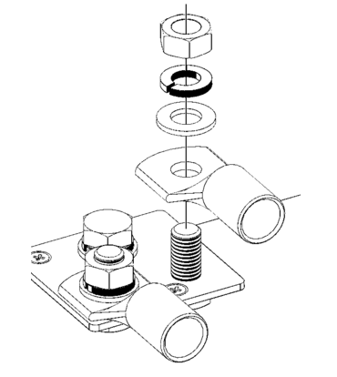
 | Use a torque wrench with insulated box spanner in order to avoid shorting the battery. Maximum torque: 14 Nm Avoid shorting the battery cables. |
To access the battery terminals, undo the two screws at the bottom of the enclosure and remove the cover to expose the service compartment.
|
|
|
|
3.4. Solar array configuration
The Inverter RS Solar single tracker model contains multiple PV input connectors. However these are internally connected to one single Maximum Power Point Tracker. It is strongly recommended that the connected strings are made with the same number and type of panels.
Warning
Always use genuine Staubli MC4 connectors for the PV connections to the Inverter RS Smart Solar.
Connectors from other brands may not be fully compatible with the Staubli connectors on the Inverter RS Smart Solar.
The Inverter RS Smart Solar is built using Staubli MC4 connectors. There are many other brands available, but some manufacturing variations mean that they may make poor contact and cause excessive heat. There are also inferior brands on the market which will likely cause problems.
Warning
The maximum rated voltage of the solar charger is 450 V. A PV overvoltage event will damage the solar charger. This damage is not covered by warranty.
In case the PV array is located in colder climates the PV array can output more than its rated Voc. Use the MPPT sizing calculator on the solar charger product page to calculate this variable. As a rule of thumb, keep an additional 10% safety margin.
The maximum operational input current for each tracker is 12 A.
MPPT PV inputs are protected against reverse polarity, to a maximum short circuit current of 16 A for each tracker.
Connecting PV arrays with a higher short circuit current is possible, up to an absolute maximum of 30A, as long as connected with correct polarity. This outside of specification potential allows for system designers to connect larger arrays, and can be useful to understand in case a certain panel configuration results in a short circuit current just slightly above the maximum of the reverse polarity protection circuit.
Warning
BEWARE that the product warranty will be void if a PV array with a short circuit current larger than 16 A array is connected in reverse polarity.
When the MPPT switches to float stage it reduces battery charge current by increasing the PV Power Point voltage.
The maximum open circuit voltage of the PV array must be less than 8 times the minimum battery voltage when at float.
For example, where a battery has a float voltage of 54.0 volts, the maximum open circuit voltage of the connected array cannot exceed 432 volts.
Where the array voltage exceeds this parameter the system will give a "Over-charge Protection" error and shut down.
To correct this, either increase the battery float voltage, or reduce PV voltage by removing PV panels from the string to bring the voltage back within specification.
3.5. Cable connection sequence
First: Confirm correct battery polarity, connect the battery.
Second: if required, connect the remote on-off, and programmable relay, and communications cables
Third: Confirm correct PV polarity, and then connect the solar array (if incorrectly connected with reverse polarity, the PV voltage will drop, the controller will heat up but will not charge the battery).
3.6. Connection to the load
Never connect the output of the inverter to another AC supply, such as a household AC wall outlet or AC wave forming petrol generator. Wave synchronising PV solar inverters can be connected to the AC output, see section on Frequency Shift Function for more information.
Follow the local national wiring standards, regulations and installation instructions for electrical work.
A Type A RCD can be used.
| The Inverter RS Smart Solar is a safety class I product (supplied with a ground terminal for safety purposes). Its AC output terminals and/or grounding point on the outside of the product must be provided with an uninterruptible grounding point for safety purposes. The Inverter RS Smart Solar is provided with a ground relay that automatically connects the Neutral output to the chassis. This ensures the correct operation of the internal earth leakage switch and an earth leakage circuit breaker that is connected to the output. ─ In a fixed installation, an uninterruptable grounding can be secured by means of the grounding wire of the AC input. Otherwise the casing must be grounded. ─ In a mobile installation (for example, with a shore current plug), interrupting the shore connection will simultaneously disconnect the grounding connection. In that case, the casing must be connected to the chassis (of the vehicle) or to the hull or grounding plate (of the boat). Torque: 1.2 Nm |
3.7. VE.Direct
This can be used to connect a PC/laptop to configure the inverter with a VE.Direct to USB accessory. Can also be used to connect a Victron GlobalLink 520 to allow for remote data monitoring.
Note
The VE.Direct port on the Inverter RS Smart Solar cannot be used to connect to a GX device, and the VE.Can connection must be used instead.
3.8. VE.Can
Used to connect to a GX Device, and/or daisy-chain communications to other VE.Can compatible products such as the VE.Can MPPT range.
3.9. Bluetooth
Used to connect to the device via VictronConnect for configuration.
3.10. User I/O
3.10.1. Remote on/off connector
The remote on/off connector has two terminals, the “Remote L” and the “Remote H” terminal.
The Inverter RS Smart Solar ships with the remote on/off connector terminals connected to each other via a wire link.
Note that for the remote connector to be operational, the main on/off switch on the solar inverter needs to be switched to “on”
The remote on/off connector has two different operational modes:
On/off mode (default):
The default function of the remote on/off connector is to remotely switch the unit on or off.
The unit will switch on if “Remote L” and the “Remote H” are connected to each other (via a remote switch, relay or the wire link).
The unit will switch off if “Remote L” and the “Remote H” are not connected to each other and are free floating.
The unit will switch on if “Remote H” is connected to battery positive (Vcc).
The unit will switch on if “Remote L” is connected to battery negative (GND).
2-wire BMS mode:
This feature can be enabled via VictronConnect. Go to the Battery settings page, and then to “Remote mode”.
Set the remote mode from “on/off” to “2-wire BMS”.
In this mode, the “load”, “load disconnect” or “allowed to discharge” signal and the “charger”, “charger disconnect” or “allowed to charge” signals from a Victron lithium battery BMS are used to control the unit. They respectively turn the inverter off in case discharge is not allowed, and turn the solar charger off if charging is not allowed by the battery.
Connect the BMS “load”, “load disconnect” or “allowed to discharge” terminal to the Inverter RS Smart “Remote H” terminal.
Connect the BMS “charger”, “charge disconnect” or “allowed to charge” to the unit Inverter RS Smart “Remote L” terminal.
3.10.2. Programmable relay
Programmable relay which can be set for general alarm, DC under voltage or genset start/stop function. DC rating: 4A up to 35VDC and 1A up to 70VDC
3.10.3. Voltage sense
For compensating possible cable losses during charging, two sense wires can be connected directly to the battery or to the positive and negative distribution points. Use wire with a cross-section of 0,75mm².
During battery charging, the charger will compensate the voltage drop over the DC cables up to a maximum of 1 Volt (i.e. 1V over the positive connection and 1V over the negative connection). If the voltage drop threatens to become larger than 1V, the charging current is limited in such a way that the voltage drop remains limited to 1V.
3.10.4. Temperature sensor
For temperature-compensated charging, the temperature sensor (supplied with the unit) can be connected. The sensor is isolated and must be fitted to the negative terminal of the battery. The temperature sensor can also be used for low temperature cut-off when charging lithium batteries (configured in VictronConnect).
3.10.5. Programmable analog/digital input ports
The product is equipped with 2 analog/digital input ports, they are labelled AUX_IN1+ and AUX_IN2+ on the removable User I/O terminal block.
The digital inputs are 0-5v, and when a input is pulled to 0v it is registered as 'closed'
These ports can be configured in VictronConnect.
Unused: the aux input has no function.
Safety switch: the device is on when the aux input is active.
You can assign different functions to each aux input. In case the same function is assigned to both aux inputs then they will be treated as an AND function, so both will need to active for the device to recognise the input.
3.10.6. User I/O terminal diagram

User I/O Connector is located on bottom left side of connection area, diagram shows 3 perspectives. Left Side - Top - Right Side
3.10.7. User I/O functions
Number | Connection | Description |
|---|---|---|
1 | Relay_NO | Programmable relay Normally Open connection |
2 | AUX_IN - | Common negative for programmable auxiliary inputs |
3 | AUX_IN1+ | Programmable auxiliary input 1 positive connection |
4 | AUX_IN2+ | Programmable auxiliary input 2 positive connection |
5 | REMOTE_L | Remote on/off connector Low |
6 | REMOTE_H | Remote on/off connector High |
7 | RELAY_NC | Programmable relay Normally Closed connection |
8 | RELAY_COM | Programmable relay common negative |
9 | TSENSE - | Temperature Sensor negative |
10 | TSENSE + | Temperature Sensor positive |
11 | VSENSE - | Voltage Sensor negative |
12 | VSENSE + | Voltage Sensor positive |
3.11. Large systems - Parallel and 3 phase
Warning
Parallel and 3 phase systems are complex. We do not support or recommend that untrained and/or inexperienced installers work on these size systems.
If you are new to Victron, please start with small system designs, so that you become familiar with the necessary training, equipment and software required.
It is also recommended to hire an installer that has experience with these more complex Victron systems, for both the design and the commissioning.
Victron is able to provide specific training for these systems to distributors via their regional sales manager.
Note
VE.Can parallel and 3 phase networking differs from VE.Bus. Please read the documentation in full, even if you have experience with large VE.Bus systems.
Mixing different models of Inverter RS (ie. the model with Solar and without Solar) is possible. However mixing Inverter RS with Multi RS is not currently supported.
DC and AC wiring
Each unit needs to be fused individually on the AC and DC side. Make sure to use the same type of fuse on each unit.
The complete system must be wired to a single battery bank. We do not currently support multiple different battery banks for one connected 3 phase and/or parallel system.
Communication wiring
All units must be daisy chained with a VE.Can cable (RJ45 cat5, cat5e, or cat6). The sequence for this is not important.
Terminators must be used at either ends of the VE.Can network.
The temperature sensor can be wired to any unit in the system. For a large battery bank it is possible to wire multiple temperature sensors. The system will use the one with the highest temperature to determine the temperature compensation.
Programming
All settings need to be set manually by changing the settings in each device, one by one. For now synchronising settings to all devices is not supported by VictronConnect.
There is a partial exception to this - changing the AC output voltage will temporarily be pushed to other synchronised devices (to prevent undesired power flow imbalance via the AC output). However this is not a permanent settings change and still needs to be manually set on all devices if you wish to change the AC output voltage.
Charger settings (voltage and current limits) are overridden if DVCC is configured and if a BMS-Can BMS is active in the system.
System Monitoring
It is strongly recommended that a GX Family Product is used in conjunction with these larger systems. They provide highly valuable information on the history and performance of the system.
System notifications are clearly presented and many additional functions are enabled. Data from VRM will greatly speed support if it is required.
3.12. Parallel installation
It is possible to install up to 12 units in a parallel system via a VE.Can network.
Connecting units in parallel provides several key benefits:
Increased power available for inverter output and battery charging
Increased redundancy, allowing for continuous uninterrupted operation when a single unit (or more) is offline.
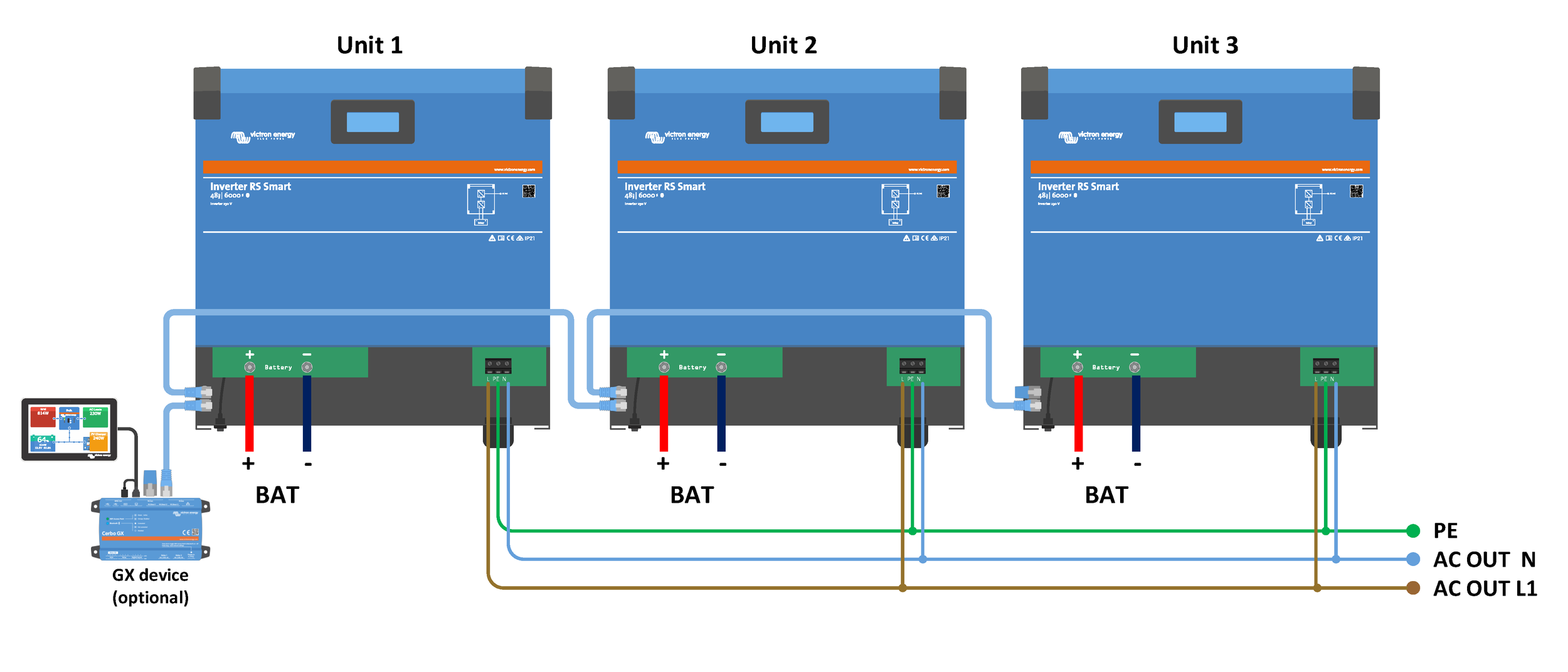
For parallel systems it is not necessary that DC wiring be symmetrical between units.
AC wiring needs to be symmetrical from the inverters to the common AC output connection. Variations in this can result in a voltage drop and different units will not share equal output power to the load.
Inverters must be configured to be synchronised before operation.
3.13. 3 phase installation
The Inverter RS Smart Solar supports single phase, and three phase configurations. It does not currently support split phase.
The factory default is for stand alone, single unit operation.
If you wish to program for three phase operation, it requires at least 3 units.
The maximum supported system size is 12 units in total.
Each phase should have the same number of units each, with a maximum of four units per phase in a three phase system.
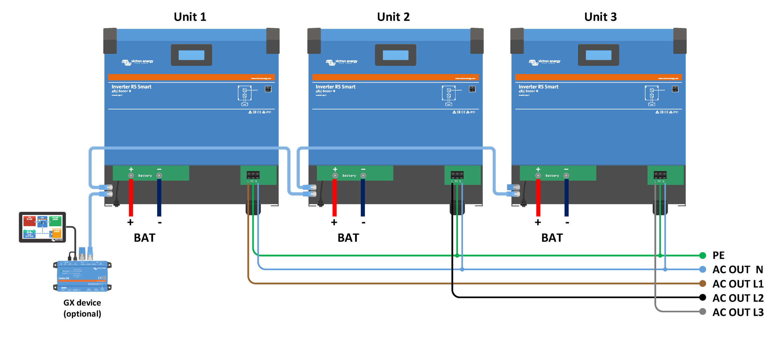
They must be connected to each other via VE.Can connections, with a VE.Can terminator at the start and the end of the bus.
Once the units are connected to the battery and via VE.Can they will need to be configured.
Delta configurations not supported
For units in 3 phase configuration: Our products have been designed for a star (Y) type three phase configuration. In a star configuration all neutrals are connected, a so called: “distributed neutral”.
We do not support a delta (Δ) configuration. A delta configuration does not have a distributed neutral and will lead to certain inverter features not operating as expected.