3. Installation
3.1. Installing and wiring the split-core current transformers
Note the following when installing the split-core current transformers :
It is not allowed to use the current clamps on bare wires.
As the current transformers are quite delicate, the following procedure should be followed when installing the current transformers:
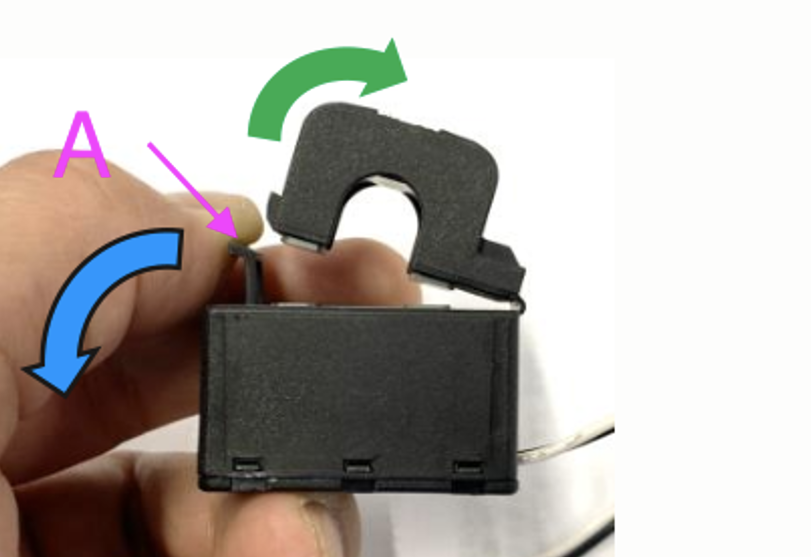
First, open Section A. Be careful not to twist the head.
The head part of the product will naturally lift off.
Clamp the head part by hand.
Make sure the current transformers are connected to the correct phase wire and input terminal. The transformers are marked with an indicator showing which input port they belong to. The devices are calibrated at the factory, and accuracy will decrease if the current transformers are not matched to the correct input.
There is an arrow printed on the CT labelled L ← K. Ensure the arrow points towards loads.

Make sure the correct wires are connected to the voltage terminals. The device could be damaged if two phase wires are connected to the neutral and L1 input.
Extending the wires of the split-core current transformers
The wires of the current transformers can be extended if necessary, but note that this will increase the measurement noise slightly.
In general: The longer the cables, the higher the noise floor. However, if the length is doubled, the additional error is still low (almost 0A).
To minimise induced noise, it is recommended to twist the wires like the wires supplied with the device.
Note
Should a split-core transformer become damaged, you can order a replacement from your Victron dealer or via this link.
3.2. Power wiring and overcurrent protection
The VM-3P75CT includes a built-in, non-replaceable fuse that protects its internal circuitry. When the same wire gauge is used to connect the VM-3P75CT as for the rest of the circuit downstream of the main breaker, no additional circuit breaker is required. In most European installations, 2.5 mm² wiring protected by a 16 A breaker is used, which is also suitable for the VM-3P75CT.
If a different wire gauge is used, a separate circuit breaker must be installed in accordance with applicable national wiring regulations. This requirement ensures that the overcurrent protection device, typically a circuit breaker, corresponds to the smallest wire gauge in the circuit [1].

VM-3P75CT circuit protection
3.3. Wiring examples by application
General AC wiring examples
 VM-3P75CT 3-phase wiring when used as a grid meter |  VM-3P75CT 1-phase wiring when used as a grid meter |  VM-3P75CT split-phase wiring when used as a grid meter |
Specific AC wiring examples depending on application and role

VM-3P75CT 3-phase wiring - Role is set to measure AC loads

VM-3P75CT 3-phase wiring - Role is set to measure a PV Inverter (or Generator)
3.4. Ethernet and VE.Can wiring
The VM-3P75CT can be connected to the GX device either via VE.Can or Ethernet.
Suppose there is a local network with an Ethernet connection (via a router) to which the GX device is connected via Ethernet or WiFi. In that case, connecting the energy meter to the same network via Ethernet is reasonable.
Alternatively, you can connect the energy meter directly to the GX device via its VE.Can connectors. Ensure that the VE.Can network is properly terminated at both ends with the supplied VE.Can terminators.
For both applications, use a good quality Ethernet cable such as the Victron RJ45 UTP Cable, which can also be purchased from your Victron dealer in different lengths.
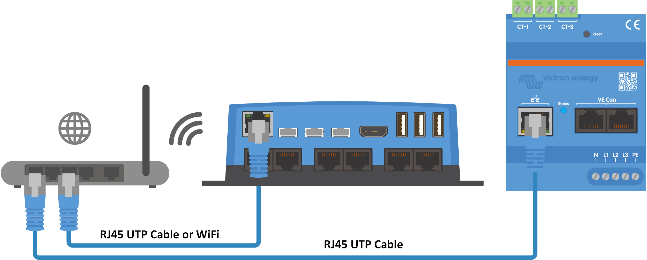
The VM-3P75CT connected to the GX device via Ethernet
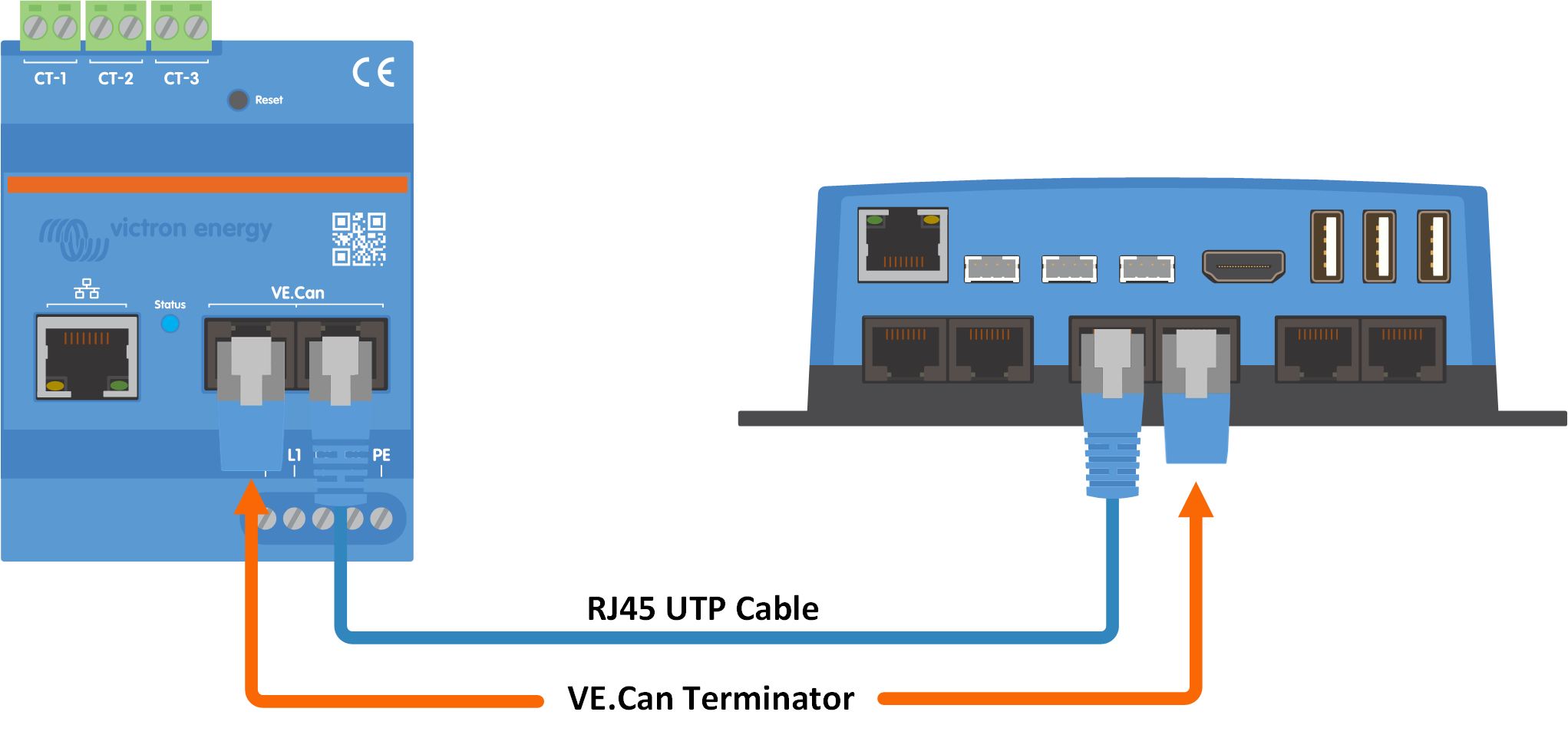
The VM-3P75CT connected to the GX device via VE.Can