4. The User Interface
4.1. User interface introduction
To follow this manual, ensure the "New UI" user interface is enabled on your GX device: Settings → General → Display & Appearance → User interface.
The user interface offers a clean and intuitive layout that simplifies navigation and improves data visibility.
Features
Remote Console: Remote Console: Runs locally in your browser (via LAN or VRM) and communicates directly with the GX device.
Light and dark modes: Optimised for varying light conditions. Dark mode is enabled by default.
4.2. The Brief Page
The Brief page provides a clear overview of key system data via a customisable ring-style widget.
Configuration options are available in Settings → General → Display & Appearance → Brief page:
To adjust data units for temperature, volume, or electrical power, go to Settings → General → Display & Appearance → Data units. For details, refer to the next section. |    |
4.3. The Overview Page
The layout provides a comprehensive view of your system in a single location, enabling easy monitoring, control and management.
The Overview Page is divided into three sections:
A button at the top left (accessible from any page) opens the control panel, providing quick access to:
All items with a blue outline are tappable and open a detailed view. |  |
4.4. The Settings menu
The Settings menu is organised into high-level categories for easier navigation. Breadcrumbs are displayed at the top of the screen, showing the current location within the menu. With a single tap, you can return to any level in the menu structure.
For example, if the path shown is Settings > General > Date & Time, tapping General will return to the General menu, while tapping Settings will return to the main Settings menu. |   |
4.5. Data units
The Data units submenu allows configuration of the units and display formats used throughout the GX device interface.
Temperature: Select the unit used for temperature values:
|  |
Volume: Select the unit used for volume measurements:
|  |
Electrical power display: Select how electrical values are displayed:
|  |
Format: Select the coordinate format used for GPS data:
|  |
Speed unit: Select the unit used for speed values:
|  |
4.6. The Switch pane
The Switch pane is a quick-access control panel, available via touchscreen, Remote Console, Marine MFD HTML5 App, or VRM, for managing switching functions in vehicles, boats, or stationary systems.
When using the Marine MFD HTML5 app, the Switch pane is available on the MFD display. This allows control of GX onboard relays, supported Shelly devices and Node-RED virtual switches.
Supported devices
GX internal relays: Relay connections
Safiery STAR-Power, STAR-Light, and STAR-Rover digital switching controllers
A button in the top-left corner of the UI opens this pane, providing control over digital outputs, relays, and other systems on supported devices. This button is only visible when a supported device is connected. |  |
The layout of the Switch pane is determined by the configuration set in the Setup menu of each connected device. Outputs can be grouped to simplify the interface, especially useful when managing multiple outputs. |  |
Supported devices for the Switch pane are configured through the device’s Setup menu. The following options are available:
|  |
Supported control elements: Most of the control elements listed below are only available when using the Virtual Switch (Node-RED) integration. Hardware-based switching devices typically provide only the first three basic output controls.
|   |
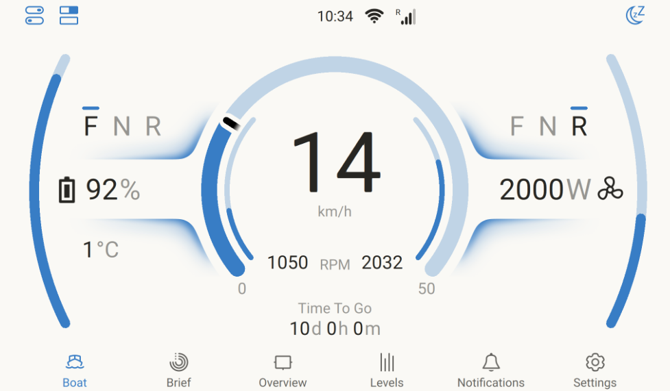
4.7. The Boat Page
The Boat page is designed for electric and hybrid boats, combining battery status, engine RPM, GPS data and electric drive information on a single display.
Data can be received via NMEA 2000 or CANopen (VE.Can) for compatible electric propulsion systems, from a Victron SmartShunt configured as a DC Energy Meter – Electric Drive, or via custom Node-RED integration. Multihull vessels and dual-engine setups are supported, including configurable port and starboard electric drives.
The Boat page appears in the menu alongside the Brief and Overview pages, and can also be accessed remotely via VRM or on a GX display.
For a short introduction to the Boat page and its features, see the video below:
4.7.1. Compatible systems
NMEA 2000 compatible systems
FischerPanda - Communication Interface Electric Drive - NMEA 2000®
Vetus - Vetus CANverter
Combi - CAN Converter NMEA
WaterWorld - WaterWorld NMEA-Connect
CANopen compatible systems and controllers
Compatible E-drive systems:
Oceanvolt
Kräutler
Törkmar
Compatible plug-and play motor controllers:
Sevcon Gen4 AC
Curtis F series
Curtis 123X E/ES series
4.7.2. How to integrate
The Boat page can combine data from different sources, such as GPS and electric propulsion systems. Integration is possible through Victron devices, NMEA 2000 networks, CANopen, or custom solutions. The following options show how to connect GPS and propulsion data to the GX device.
GPS
Electric Propulsion
|   |
4.7.3. Integration examples
Example 1: SmartShunt
For boats with only a SmartShunt measuring an electric drive, the Boat page shows:
|  |
Example 2: SmartShunt plus GPS
Same as Example 1, plus GPS. The Boat page shows:
|  |
Example 3: NMEA2000-integrated propulsion engine
For propulsion integrated via NMEA 2000, the Boat page shows:
|  |
Example 4: NMEA2000-integrated propulsion engine with GPS
Same as Example 3, plus GPS. The Boat page shows:
|  |
4.7.4. Configuration & GX device monitoring
The Boat page can be customised to suit your preferences. Select the data units that best match your application, while gauge scaling for power, speed, and RPM is set automatically or can be adjusted manually if required.
To enable the Boat page, go to
|  |
Configure your preferred data units via
The minimum and maximum values for the power, speed and RPM gauges can be configured via
|   |
GX device monitoring
A connected E-drive or motor controller appears in the Devices list and provides information such as:
|  |
The Device menu provides additional information for the connected E-Drive or motor controller and allows a custom name to be set for clear identification. |  |
4.7.5. CANopen integration for electric propulsion systems
Venus OS supports the CANopen profile for integration with electric propulsion systems and Sevcon and Curtis motor controllers, enabling monitoring on the GX Boat page and in VRM.
|  |
4.7.6. Multihull / dual engine setup support
Venus OS supports multihull / dual engine setups.
For dual electric drive systems, the following parameters are supported:
|  |
When dual engines are connected, the Boat page configuration (Settings → General → Display & Appearance → Boat page) provides additional options and allows the E-drive to be assigned to the left and right side respectively. |   |
4.7.7. VRM Monitoring
The data relevant to the electric propulsion system is made available on VRM, including detailed data in the Advanced section of VRM. |  |
4.8. The Support status (modification checks) page
The Modification checks page is available under Settings → General. It provides a clear indication of whether the GX device is running in its standard configuration or has been modified.
This page helps users, installers, and distributors recognise system modifications quickly and, if required, restore the device to its standard configuration. This reduces time spent on support and troubleshooting.
To check the support status:
Note: Items shown in orange are supported and provided by Victron Energy. However, incorrect use can affect system stability. During troubleshooting, disable these items first. The GX device also monitors the free space in the data partition and raises an alarm when the available space drops below 10%. ImportantA full data partition is only a concern on GX devices running the Venus OS Large image image, or on systems that have been modified for advanced usage. To increase free space, follow the instructions in the Victron Node-RED/Signal K documentation. |  |
4.9. Network security profile
The Network security profile setting allows you to control how data is exchanged locally (via Ethernet or WiFi) and remotely (via VRM).
You can choose from three profiles:
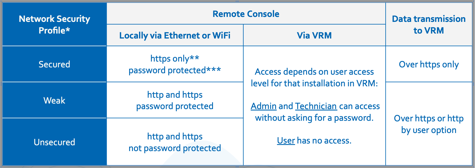
* When upgrading from a version prior to v3.50, the profile is automatically set to match the previously configured network and Remote Console settings. New devices shipped with v3.50 or later default to Secured.
** Any access on http will be redirected to the https equivalent.
*** On new units shipped with v3.50 or later, the default device password is the same six-digit random PIN used for Bluetooth, printed on the enclosure on the GX device. When upgrading an existing GX device, the security profile is automatically configured to match the current user-defined settings, such as whether Remote Console over LAN is enabled and password protected.
Changes to the security profile can be made under Settings → General → Access & Security → Local network security profile in the Settings menu. |  |
Network security profile details
The Network security profile setting applies exclusively to local network access. It does not affect physical device access or the on-screen access level setting (User / User & Installer), which are configured separately.
When accessing the Remote Console over LAN via HTTPS, your browser will display a certificate warning. This must be accepted to proceed.
Once logged in to the Remote Console over LAN or WiFi, the browser session remains active for 365 days before requiring a new login.
Recovering a lost network access password
If the network access password is lost, it can be reset using one of the following methods, depending on the GX device model:
Press and hold the physical push-button to reset all passwords, including the network access password. After reboot, the password is reset to the default (if the device was shipped with one). For devices without a factory-installed password, this action will disable the network access password.
Insert a USB stick configured as a "Reset to factory defaults" stick and reboot the device. Refer to Reset to factory defaults procedure for instructions on creating the USB stick.
Notes:
The device password can be changed and must be at least 8 characters long.
The Bluetooth PIN remains fixed at six digits, as per Bluetooth standards.