Douglas Edmond Steinman, Chris Wallace-Tarry • 12 Sept 2026
How to size an RV battery bank
Learn more
How to wire your RV battery connection
Once you’ve chosen your leisure battery type and sized it to your usage, it’s time to tackle the installation. Besides the batteries themselves, you’re likely looking at a pile of lugs, cables, and fuses, wondering how it all goes together. This article will cover your RV battery connection, starting with terminal hardware and stack order, how to wire batteries in parallel and in series and how to ensure batteries are balanced, BMS integration, battery fuses, and battery busbars.
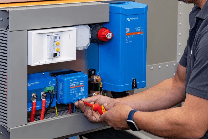
If short circuited, leisure batteries can deliver dangerously high currents; enough to weld a spanner to a terminal, burn through cable insulation, or start a fire. Flooded lead-acid batteries carry an extra risk, because they give off hydrogen while charging and a spark can ignite it. Advice around battery connection order seeks to prevent short circuits, but it’s also important to isolate the batteries entirely before getting to work. Turn off all battery chargers (solar charge controller, DC-DC charger, battery charger) and loads, and remove the fuses. This is where a battery isolator switch is handy, as it allows you to isolate the batteries from a single point. Remove all metal jewelry, and use insulated tools whilst working on your batteries.
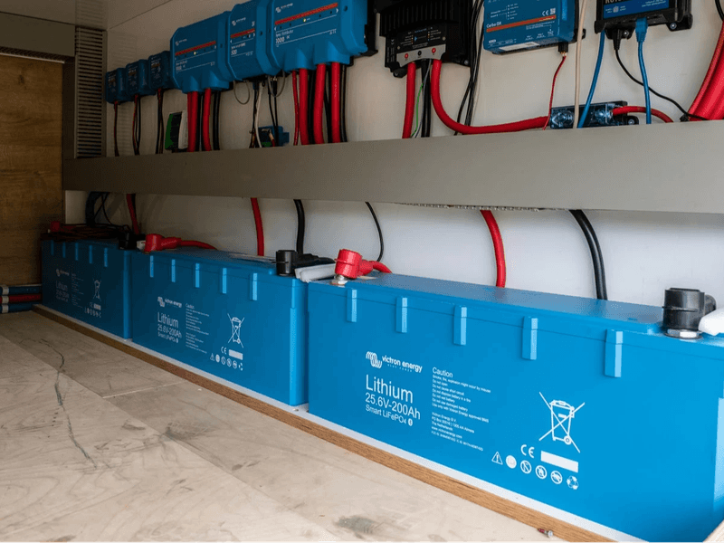
If you’re making a battery bank out of multiple smaller batteries (in a series or parallel-connected bank), it’s best to use batteries of the same model, capacity, age, and chemistry.
Batteries rarely arrive at the same state of charge. Lithium batteries leave the factory around half charged for transport safety, and storage and shipping change that further. In a parallel bank the batteries even out on their own, but in a series bank they can’t: cell balancing inside each battery can only correct small differences between batteries. Before building a series or series-parallel bank, charge each battery fully on its own. For lithium batteries, use a BMS-controlled charger and check that each battery’s cells show as balanced before connecting it into the bank. Charge lead-acid batteries individually with the correct charge profile. Your battery manual describes the full procedure.
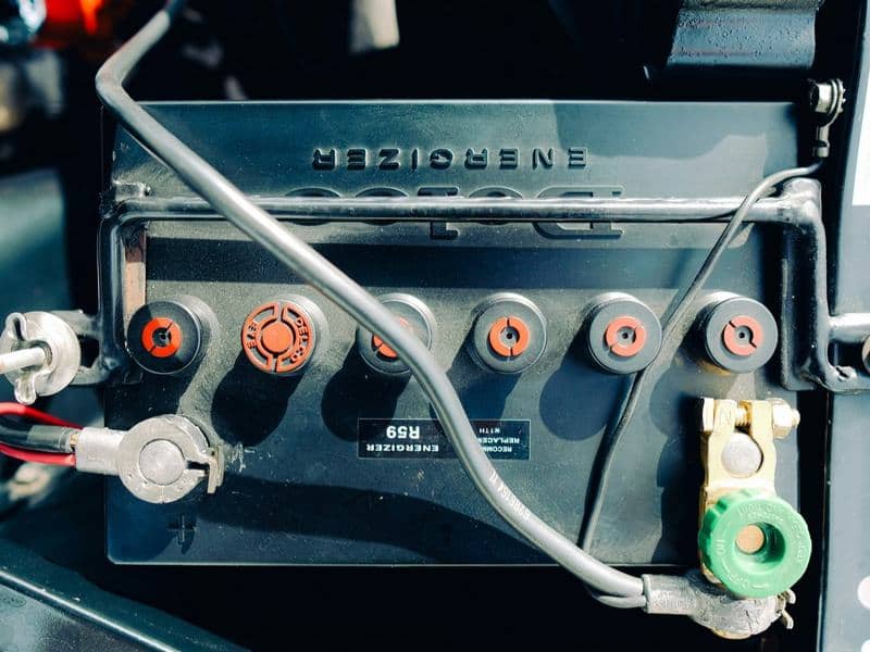
The battery terminals are where wires connect to your batteries. Lithium batteries and most AGM and gel batteries use threaded inserts, receive either M8 or M10 bolts (usually included with the battery); check the product manual for your battery for confirmation. Flooded lead-acid batteries may use tapered posts.
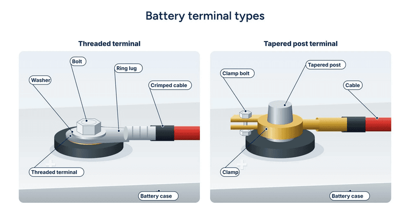
Crimp-on ring lugs should be used to connect to bolt terminals. These lugs should be sized correctly to both your battery cable and the bolt, crimped to the cable with an appropriate crimping tool, and finished with heat-shrink tubing.
Clamp terminals should be used to connect to tapered posts. These must also be sized appropriately for the cable and the post. It’s also possible to use stud clamps (also called post-to-stud adapters) to attach a threaded stud to a tapered post. This effectively turns it into a bolt terminal.
Battery terminal clamp polarity
Battery terminal clamps are polarity-specific. The positive post is larger than the negative, so clamps are not interchangeable. Use a positive clamp on the positive post, and a negative clamp on the negative post.
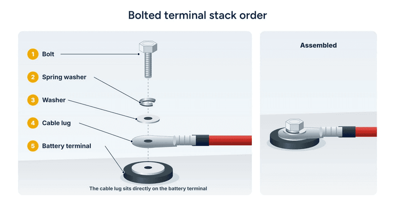
When connecting to bolt terminals, washers must be used to ensure uniform clamping force on the ring lug. The correct RV battery terminal stack order, from the top down, is:
Because you isolated the battery, short circuits through other electrical components can’t happen. However, it’s still possible to short the battery by touching both terminals or the van chassis with the spanner you’re using. Always use an insulated spanner to tighten your terminal bolt, and connect positive cables first, then negative cables. When disconnecting batteries, reverse this order.
Battery terminal bolt tightness
An overly loose terminal bolt creates a local hotspot which can damage the battery or start a fire. An overly tight terminal bolt can strip the threaded insert and damage the terminal. Tighten all terminal connections to the torque specified in the product manual using a torque wrench.
When connecting to post terminals, ensure full contact between the terminal clamp and the terminal. Loosen the pinch bolt on the clamp until it slides onto the terminal post freely. Push it down by hand until it sits against the terminal at the bottom of the post. Torque the pinch bolt to the clamp manufacturer’s specified figure, and check that the clamp won’t turn on the post. For a stud clamp, now follow the same procedure as for bolt terminals.
For both bolt and post terminals, make sure every positive terminal is fitted with a terminal cover.
When planning your RV battery connection wiring, remember that a series setup raises voltage, a parallel setup raises capacity, and a series-parallel setup raises both voltage and capacity. Read all about these setups in our article on series vs. parallel battery wiring. Each of these setups requires different fusing, covered in a later section.
When wiring RV batteries in parallel, the positives of each battery are connected together, and the whole positive chain is connected to the positive battery bank output (either a positive busbar or post). The negatives of each battery are then all connected together, and the negative chain is connected to the bank output.
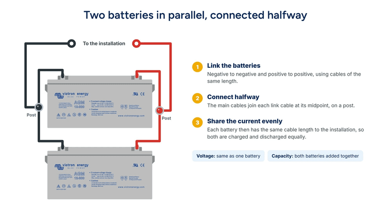
A common mistake is to connect all the batteries together, then to simply connect the last battery in the chain straight to the bank output. As discussed in our series vs. parallel article, this creates an unequal load across the batteries in the parallel bank. The battery closest to the bank output is overworked and overcharged, whilst the battery furthest up the chain is undercharged.
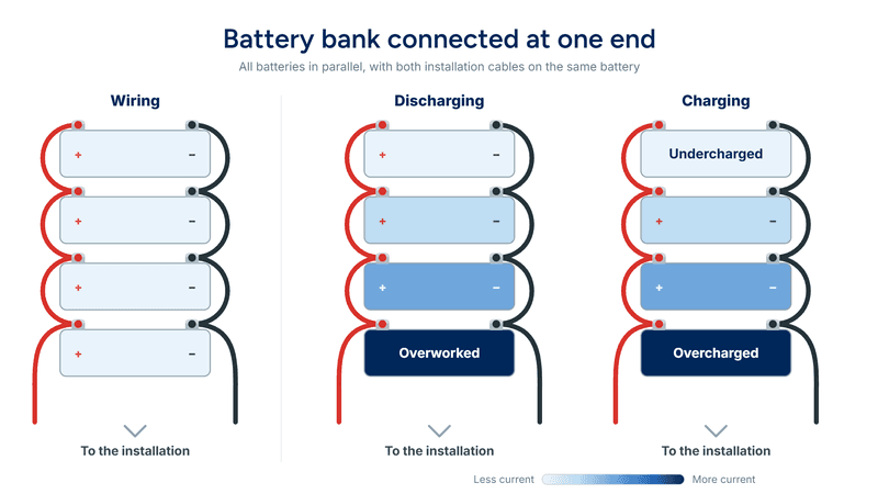
The solution is to equalise cable lengths for each battery. For a two-battery bank, a ‘diagonal’ connection is simple and acceptable. The positive terminal of battery A is connected closest to the bank output, then connected to the positive terminal of battery B. The negative terminal of battery B is connected closest to the bank output, then connected to the negative terminal of battery A. Note that the total cable lengths of the positive and negative chains should be identical.

For parallel battery banks of three or more batteries, other solutions are preferable. Cable runs should be equalised using busbars, posts, or a halfway connection. For the busbar and post solutions, make sure the runs between the busbar/post and battery terminals are all the same length.
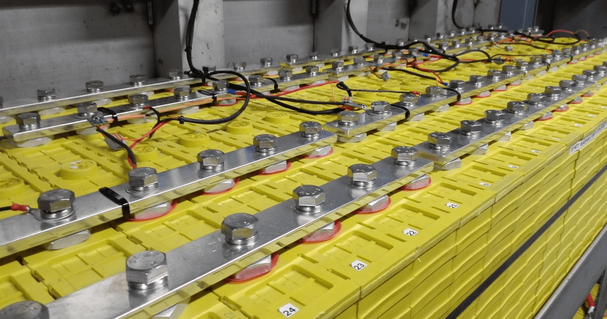
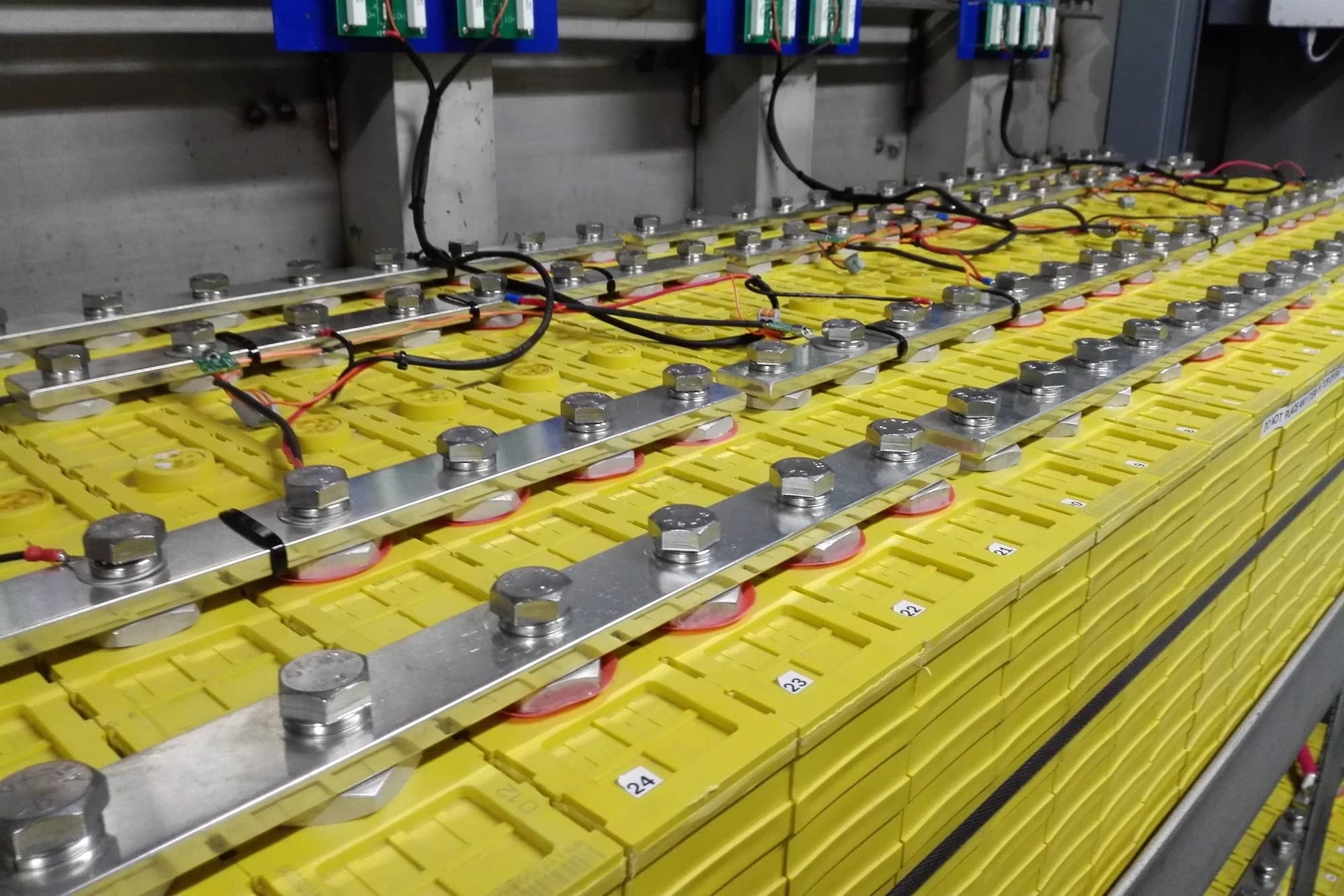
When wiring batteries in series, each battery’s positive terminal is connected to the next battery’s negative terminal with a short link. The negative terminal of the first battery and the positive terminal of the last battery are then connected to the bank outputs. Size the links between batteries like the main cables and keep them short to minimise overall voltage drop. A series-connected battery bank must be properly balanced; we’ll cover that in the next section.
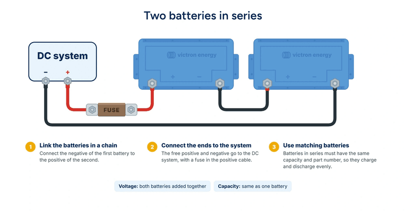
A series-parallel RV battery connection allows you to increase both voltage and capacity. For example, four 12V 100Ah batteries wired as two series strings of two, with the strings connected in parallel, make a 24V, 200Ah bank.
Series-parallel notation
For simplicity, series-parallel notation is used to describe banks wired in this way. A 2S2P bank consists of two batteries in series per string with two strings in parallel. A 3S2P bank consists of three batteries in series per string with two strings in parallel. This useful shorthand is also used when discussing solar arrays.
Wiring batteries in series-parallel involves first building each series string, then connecting the strings in parallel. As with pure parallel wiring, it’s best to use busbars or posts to equalise connections to the positive and negative terminals.
A final decision is whether or not to connect the midpoints of each parallelled string together:
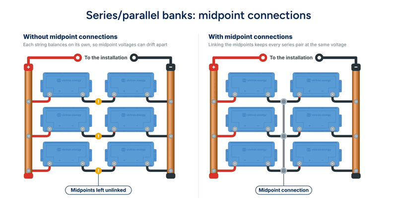
No need to join the midpoints of Victron lithium batteries
Victron lithium batteries cannot be set up in series-parallel banks with midpoints joined. Battery balancers are not needed for Victron lithium banks, so the benefit of this setup doesn’t apply.
The internal voltage of batteries wired in series can drift apart over time because, unlike with a parallel setup, each battery acts independently. The same current flows through every battery in a series string, but small differences in capacity and self-discharge mean they don’t reach full or empty at quite the same time. Each cycle widens the gap, because the battery that’s ahead is pushed further ahead. Unbalanced batteries cause problems like:
Victron lithium batteries do not require external balancing as they contain cell-balancing electronics that balance each cell individually. They do, however, require regular charging to full, as it’s during the charge phase that cell-level balancing happens. Check your battery manual for more details.
All lead-acid batteries and some non-Victron lithium batteries wired in series require external balancing (check your battery manual for confirmation). This is achieved with a battery balancer. A simple series setup requires a single battery balancer in the string, whilst a series-parallel setup requires one balancer if the midpoints of all strings are joined, or a balancer per string if the midpoints are separate. The battery balancer’s ‘COMMON’ input should be connected to the midpoint between the batteries in series. Refer to the product manual for full wiring details.
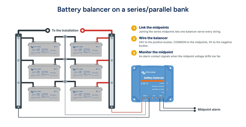
Remember that parallel banks only self-balance if the cable runs between all individual batteries are equal; this is why it’s important to use one of the balanced wiring setups discussed in the previous section for parallel setups.
A battery management system (BMS) is required for lithium battery banks, whether single batteries, or series, parallel, or series-parallel setups. A BMS protects lithium batteries against cell over-voltage, under-voltage, and temperature, all of which can quickly disable lithium batteries.
The Lithium SuperPack and Lithium SuperPack NG incorporate an integrated BMS, and don't need an external one. Smart and NG batteries must be wired with an external BMS.
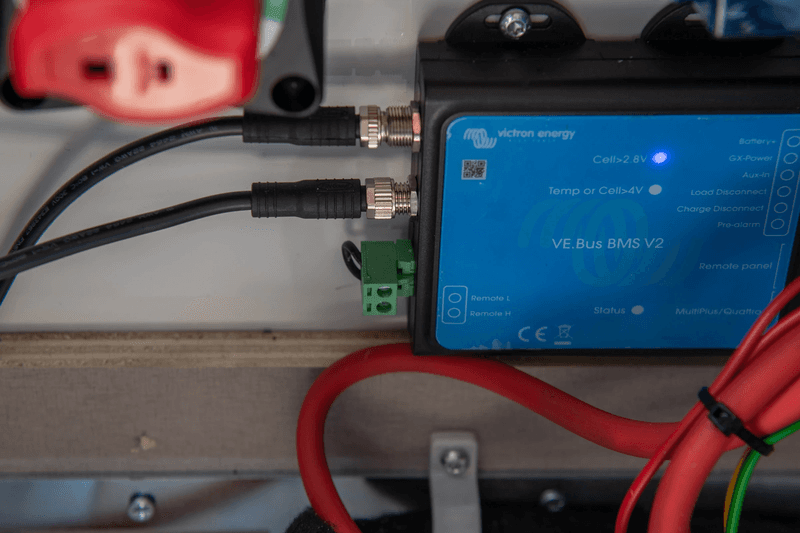
Matching the BMS to the battery
NG-series BMSs are required for NG batteries, and will not work with Smart batteries. Smart batteries must be used with compatible, non-NG BMSs.
Detailed guidance on wiring up a BMS to your batteries is provided in the battery manual; reference this document for all the information you need during your installation. In brief, each battery includes two BMS cables, corresponding to inputs on the BMS. For a single battery, connect both cables directly to the BMS. For a bank consisting of multiple batteries, connect the BMS cables of all the batteries together, and connect the remaining male and female leads to the BMS. The battery BMS cables can be interconnected in any order.
Among the NG series of BMSs, you have three options. Each is suited to a particular class of system:
Types of BMS by system
With your batteries connected together and a BMS or balancer installed, it’s time to connect your battery to the distribution points which link them into the rest of your system. We recommend using a positive and a negative busbar as main distribution points for your RV battery connection.
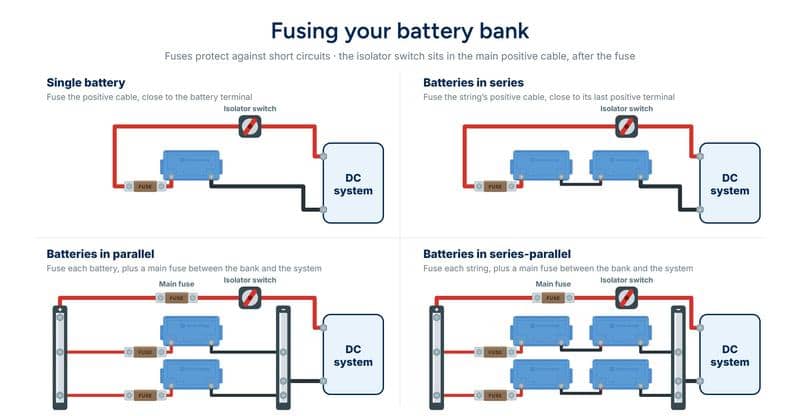
Your batteries must be fused appropriately; this is an essential safety measure which protects you, your electrical system, and your RV against short circuits. Each battery bank setup needs to be fused slightly differently:
We also recommend installing an isolator switch in the main positive connection; this allows you to easily and safely disconnect the battery bank from the system for maintenance purposes. The isolator switch should be connected into the main positive connection, after the fuse.
Sizing connections
Busbars, fuses, and isolator switches must be sized correctly, the same as wires. Consult our Wiring Unlimited ebook or speak to a certified installer for guidance.
A shunt or BMV should be installed in lead-acid banks to provide basic battery status monitoring. The shunt is connected into the main battery negative connection, close to the terminal. Every system negative connection must then also connect to the shunt’s system side.
The Lynx distribution system is a modular system that integrates busbars, battery input terminals, fuse holders, and a ground connection point, all protected by removable covers. The Lynx system can be paired with a Lynx Smart BMS NG, which provides battery monitoring and essential lithium battery management.
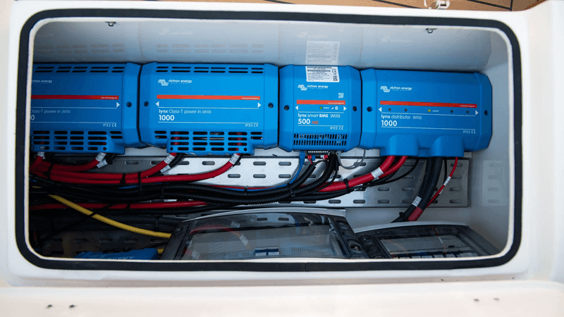
The Lynx system is useful for medium to large systems which include multiple large charging and discharging inputs, AC loads via inverter/chargers, and digital integration to the GX system. Simpler systems with single or dual-battery banks, one or two inputs and small inverters with no digital ecosystem integration would be equally well served by simple busbar pairs and a smallBMS NG or VE.Bus BMS NG.
The battery negative DC busbar is one of the points in your electrical system which must be grounded. Grounding and fusing are critical safety components that work together to protect you and your RV from short circuits. Make sure you consult our Victron Toolkit app and the Wiring Unlimited ebook for much more information. Remember, there’s no harm in seeking advice from one of our authorised distributors and installers.
The process of planning and wiring your RV battery bank should go as follows:
Setting up your RV battery connection should involve a detailed reading of the product manuals of every component in the system. Reference Wiring Unlimited and the Victron Toolkit app for technical guidance and much more information. Remember, our authorised distributors and installers are there to answer questions and make sure your system is set up correctly and safely.
Need advice? Our highly trained dealers are happy to help with questions, small or large.
Find a dealer near you
Check our support resources or contact your original dealer for dedicated support, repairs or warranty requests.
Support
Read more about our industry-leading 5-year standard warranty and global repair service.
Warranty


©Victron Energy 2026