![]()
Introduction
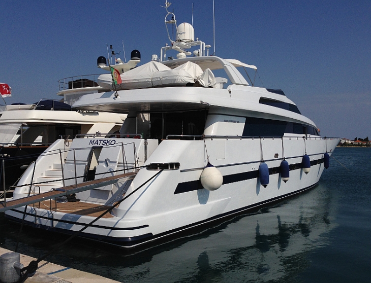
We were recently contacted by Josip Zdenković, a Director of SCHRACK TECHNIK Ltd in Croatia, who submitted a comprehensive technical article concerning the use of Victron Energy equipment on-board the vessel Matsko, shown in the headline image above.
Here then in Josip’s s own words (translated from Croatian) is his detailed article about their project. Project assistance was provided by Josip Radin, also from SCHRACK TECHNIK, who was a co-worker on the project.
Design brief: Quiet energy onboard with fuel savings
The aim of Matsko’s investment company (Fuego Ltd.) was to have an AC power supply on-board, without using a generator or shore supply. The project was assisted by the fact that Fuego had all the necessary skills to wire the installation. Based on this information SCHRACK TECHNIK were able to develop a solution and supply the system components. All of the new essential components were manufactured and supplied by Victron Energy.
Originally the vessel’s electricity was supplied by the on-board generators or shore supply. This resulted in the generators having to be used in quiet places in nature when anchored, as obviously no shore supply was available. This was particularly unwelcome at night when trying to enjoy a peaceful evening in some quiet hidden bay. Whilst no air conditioning was required throughout the evening and night, the generator was required to cover refrigerators and some lighting. Although electricity consumption was relatively small, there was always the irritation of the generator ‘muttering’ all night. Furthermore it is known that when a generator is operating in this way it is substantially under loaded, i.e. well below rated load, so unfortunately it is not running in a fuel efficient way.
Generator fuel consumption was around 4 l/h at idle, i.e. with a light load, and 6 l/h at full load. The idea was therefore to completely shut down the generator in the evening and the morning and use ‘quiet energy’ to power the refrigerator and lighting. Then if the vessel were to sail during the day, the main engines would run, with both generators working which you can then load for any additional battery charging.
This can achieve two objectives: when the generators are operating, they are working in the area of higher loads, so the better efficiency in terms of the number of litres of fuel with energy being produced more efficiently. Now any persons on-board can enjoy a peaceful sleep with ‘quiet energy’ being supplied for the night maintenance of the vessel, when at anchor. But it is also clear that by paying attention to the energy consumption at sea and when berthing in a marina connected to the shore supply, that instead of using the generators such an approach can reduce overall power consumption even further by using the silent low-cost shore energy to charge batteries, in order to be ready for sailing the following day.
All of these goals can be achieved by adding a suitable battery bank to store energy which can then be used later. This desire for tranquillity on-board also decreases the overall operating costs of the system too.
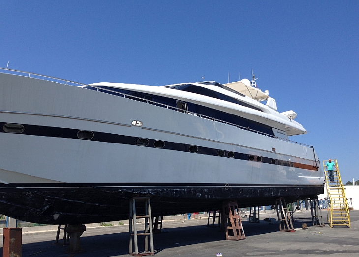
Motor Yacht Matsko
Initial equipment state
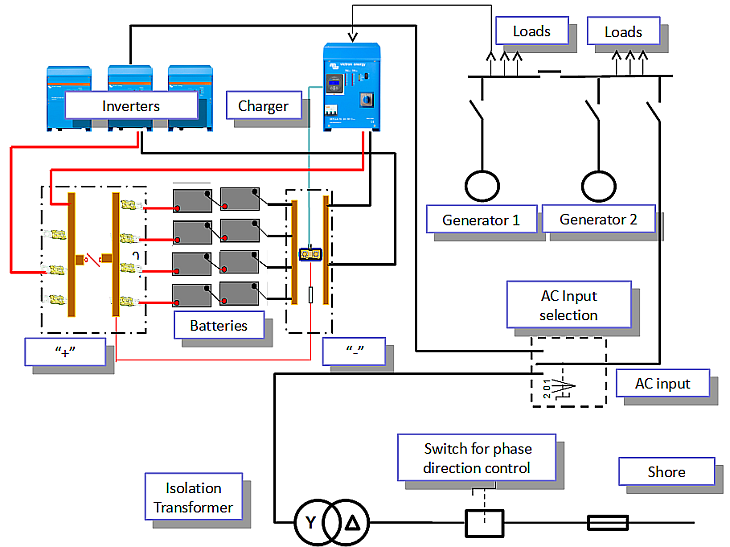
Figure 2 below is a representation of the pre-existing installation of the boat. The vessel installation is connected to shore via an isolation transformer, switch and main fuse.
Loads on vessel are supplied from generators or from shore network. In the project the power system for safety critical ship systems is not shown at all because it must stay totally independent system. The red arrow marks the insertion point for the new part of the installation discussed in this article.
Figure 2 – Simplified electrical installation of the vessel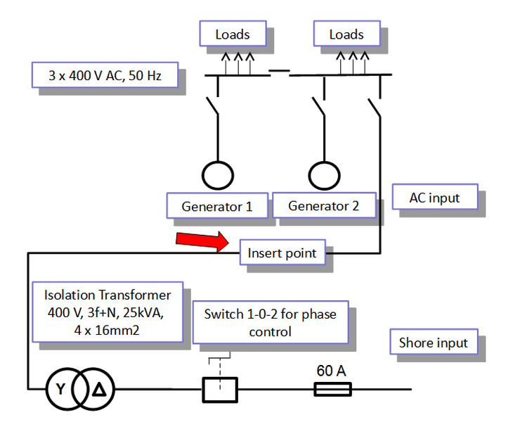
Technical solution for auxiliary power
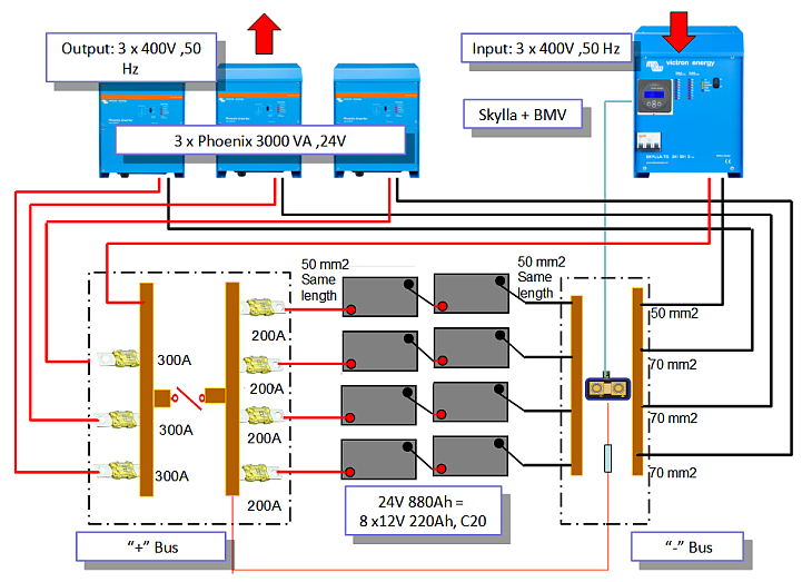
The new system has a 24 V DC battery bank , 880 Ah, C20 rated, using 8 interconnected batteries. See Figure 3.
The cable connection from the battery to the busbars must all be the same length to balance the resistance of the individual parallel branches of the batteries. At the minus pole in the distribution box the measuring shunt of the BMV battery monitor is installed. The BMV battery monitor display is supplied from the minus terminals of the battery itself connected to the measuring shunt and from the positive pole of the battery bank, as shown in Figure 3. All plus poles of parallel branches of the battery bank are connected via ‘melting fuse’ on the plus busbar. The positive busbar is connected to the main battery switch. With this switch, all systems can be disconnected from the battery (except the battery monitor which s always powered on). The batteries are recharged via a three-phase Skylla charger; charging current is 100 A. The battery charger itself is concerned that the condition of the batteries can achieve optimum charging current for the current state of charge of the battery. From the battery through three autonomous inverters of the Phoenix type, a three-phase system is obtained. This inverter system can provide 3 x 3000 VA, 400V, 50 Hz rated. And the inverter system and battery charger have control inputs managing their work. The red arrows below show the direction of energy, from input to the battery bank via the charger and from the battery bank through the inverters to the output.
Figure 3 – Auxiliary power system of the motor boat
System Description: AC part
Figure 4 below shows the wiring of the AC part, that is how the system is inserted into an AC installation. Switch S 1-0-2; the power switch, is used for the selection of the AC input of the vessel which can be powered by the shore supply or through the inverter system. The positions of switches S1-0-2 are explained in Figure 4. The charger is connected for normal loads in the vessel installation. The charger has its own input fuse so in such an installation it is not necessary to fit a new one. Inverters have overload protection built in, so in considering the point of connection and the existing protective/breaking devices in the vessel installation, there was no need for any additional special protection switches/circuit breakers.
Figure 4 – Wiring AC part of the auxiliary power system for motor boat Matsko
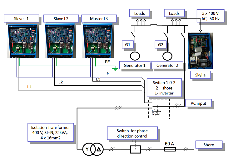
Figure 4a – Phoenix connections
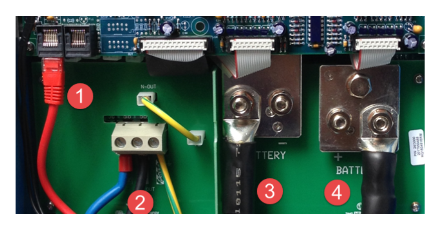
- Control terminal for the realization of the three-phase system (see Figure 7)
- AC output: phases, zero and earth
- Battery connection
- Battery connection
System Description: DC part
Figures 5 and 6 below show the wiring and detail of the DC part of the battery bank.
Figure 5 – Details of the battery bank and fuse boxes
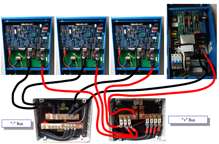
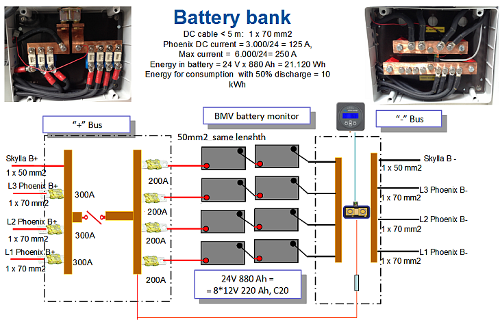 Figure 6 – Details of connecting the battery bank – connection inverters and chargers to the distribution boxes.
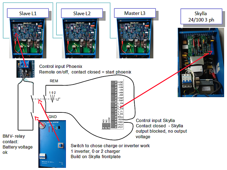
Description of the system-control unit
Figure 7 below shows the wiring for the control part.
Inverters are connected to each other via a control connection in order to achieve a three-phase system (blue cable in Figure 7).
Autonomous Phoenix inverters and charger do not operate simultaneously. When the inverter control input is in the closed condition, the inverters are supplying the voltage at the output. When this control input is in the open state, the inverters do not give the output voltage. Control input on the L1 Master unit controls the operation of all 3 inverters in this three phase system.
When the charger Skylla control input is in the closed state, then the battery is not charging. When this control input is in the open position, the charger is charging. The charger can have all the time AC power at the power input, but only when the charger control input allows, the output voltage and therefore the power for charging batteries is released.
Control switch 1-0-2, which is added on the charger housing, can choose whether inverters are working (then no charger), or the charger is working only (do not operate the inverters). Additional, inverter can only work if the relay contact from battery monitor is in the closed condition. Switched state of the relay is about the battery charge. If the battery is in good condition then inverters are operating normally. Should there be an excessive discharge of the battery, then the battery monitor relay contact is opened and that disables the inverters too. In this way, the battery bank is protected from deep discharge which enhances life expectancy. The charger is set to start charging always towards the maximum possible for the current state of charge of the battery.
Inverters have one programmable relay output each that can be used for alarm/pre-alarm conditions like that the system will soon reach the voltage level when the battery master switch off inverter operation. This contact can be used for signalling required to switch the ship again to work through the generators before inverters system does battery self-protection shut down.
Figure 7 – Management work chargers and inverters
System Description – location of components
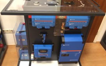
Figure 8 shows the location of the main components.
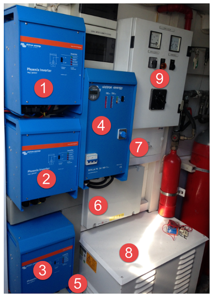
1: Inverter first phase L1
2: 2nd inverter phase L2
3: 3rd inverter phase L3 (Master unit)
4: Battery charger Skylla
5: DC “-” Busbar box
6: DC “+” Busbar box
7: Power switch 1-0-2
8: Isolating transformer
9: Existing input box to control the power supply from the shore and checking phase sequence
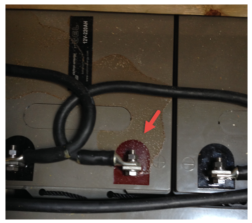
The batteries are located under the floor in the area where the equipment is located. The space is ventilated, as well as protected from dripping water. The red arrow shows how through a lack of care the water can spill onto the batteries. In this case the problem was tackled immediately so no damage was caused. It is clear than that the location choice of the batteries is extremely important. The same care must be carried out for proper inverter and charger ventilation.
Figure 9. Detail installing batteries (choose location carefully to prevent overhead drips)
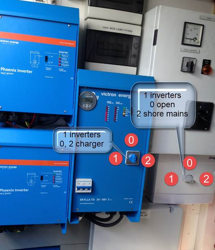
Operating system
Figure 10 below shows the location of the main components for management: power switch and control switch. Energy switch selects whether the shore network or inverters on board will supply the AC voltage to the board loads. Control switch is for selecting whether the inverters or chargers are in operation.
Listed below are characteristic situations.
The ship at sea under navigation: The energy switch is set to “2-network” or “0-opened.” Existing installation is ensuring that when on board generators are working, there cannot be shore mains voltage connection (which of course does not exist when navigating). The control switch must be 0 or 2, so that the battery charger operates and charges the battery with energy produced by generators.
The ship at sea at rest: Energy switch in position 1- inverters in operation, control switch in position 1 inverters in operation. The whole ship’s installation draws its power from “quiet” sources, the boat is powered by batteries.
The ship in the harbour with the presence of the shore supply: The energy switch is set to 2-shore supply, the control switch is set to 0 or 2, the battery charger operates and recharges the battery.
Figure 10 .: Two main elements.
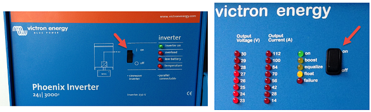
The small black switches on the inverters and on the charger faceplates (red arrows shown in Figure 11) to ensure they work must be in the “on” position. It is not necessary to alter this whilst the ship is at sea or in the harbour, so they can be permanently in the on position.
Figure 11 – Location of the switch to the exchangers, and the charger
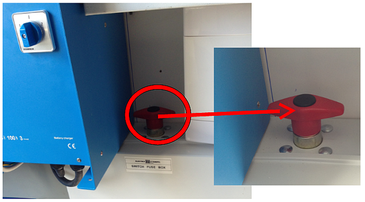
If the vessel is laid up over winter you need to turn off all devices. It is therefore recommended to disconnect the main battery switch on the “plus” side, and move the small black switches on the faceplates to off, as shown in Figure 11 above.
Figure 12 -Location of battery switch on the “+” side
In winter be sure that the main battery switch is turned off after the battery bank has been full charged first. This is important to maintain battery life. Also it is necessary at least once every two months to fully charge the batteries in order to provide the intended service life. Batteries require no maintenance other than once every two months providing a full charge! A full charge state shows the control voltage across the battery monitor. It is always on! After charging and without discharging any energy from the battery bank it must have 26V. It is especially important to emphasize that the maintenance of the battery contacts is very important too. If due to sea water, which is conductive, there is a short-circuiting of the battery the poles, that may cause irreversible destruction of the battery. Any corrosion on the terminals must be treated by regular maintenance, smearing with Vaseline grease. It is recommended to regularly check the condition of the overall battery bank, especially once every six months to look at all the electrical connections of the system and if necessary tighten them.
Figure 13 below shows the complete ship’s auxiliary power system integration in the existing installation. In this diagram you can see clearly the differences in relation to Figure 2, which shows the initial state.
Figure 13. Display systems integration auxiliary supply ship to ship existing installation.
Conclusion
We hope we have piqued your interest, and this simple yet complete depiction of this three-phase solution has demonstrated what can be achieved by “surgical” intervention to an existing installation. Of course, this system may not be fully applicable to your own case, but hopefully this may set you off on the path of emerging new ideas and thinking.
In writing this article we also felt the need to explain what an isolating transformer is in order to ground the installation on-board, what an RCD does, what galvanic and electrolytic corrosion is – well that will need wait until another time where we may cover those topics separately and more comprehensively, as such factors are an important consideration too in an installation like this.
Josip Zdenković
Credits
Josip Zdenković – article content, images and translation assistance to Victron Energy.
Josip Radin – project assistance.
Fuego Ltd. – Motor Yacht Matsko owners & investment company.
SCHRACK TECHNIK Ltd of Croatia.


