10. Description of Settings
10.1. General
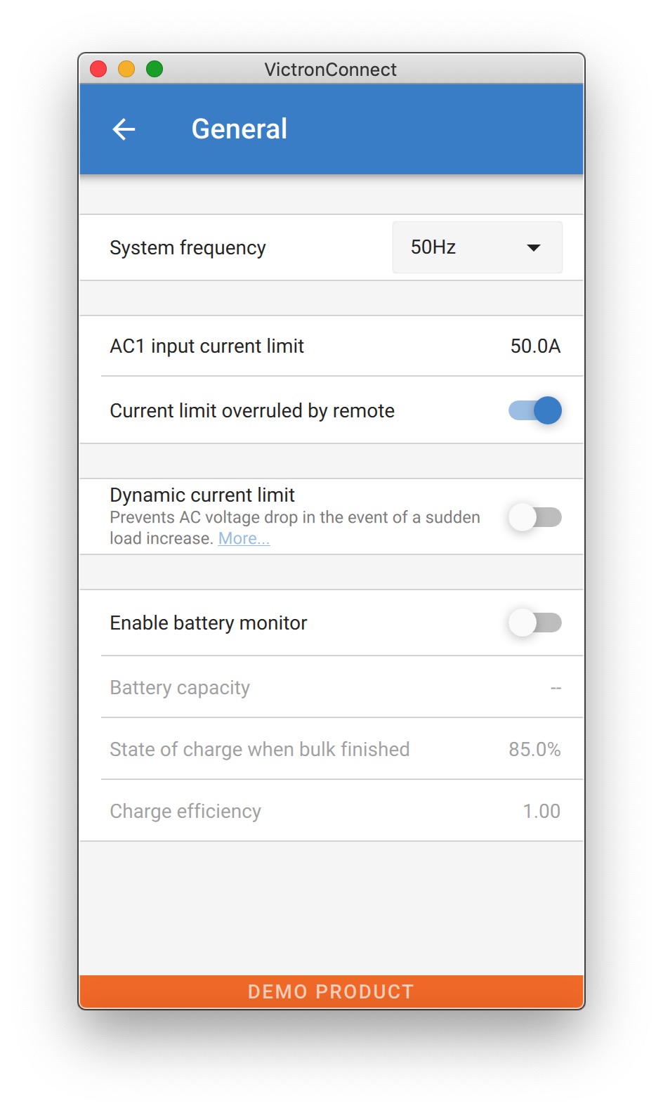 |
10.1.1. System frequency setting
Alters the output frequency setting for the inverter.
10.1.2. AC1 input current limit
This setting is only active if no system panel is installed (is overruled by the remote panel if connected).
10.1.3. Current limit overruled by remote
If Overruled by remote is enabled, the input current limit can be set remotely by a GX Device or a Digital Multi Control. If not enabled, it cannot be changed.
The use case is to typically leave it unchecked in stationary applications, as well as inputs connected to a generator, since for them the input current limit is a static value and defined during installation.
For shore connections (boat and vehicle use) you check the box, so that the user of the system can change the input current limit to match the shore connection they are currently using.
10.1.4. Dynamic current limit
Setting for use with ‘small’ generator - If an inverter-generator is used, such as the HONDA EU series, the shore current setting will be dynamically reduced (following a period of low current consumption) to compensate for the engine reaction time when higher loads are activated.
10.1.5. Enable Battery Monitor
Enabling the VE.Bus battery monitor, this also enables many features that can use a state of charge (SoC).
10.1.6. Battery capacity
In order for the battery monitor to be able to correctly calculate the "state of charge" the battery capacity of the connected batteries must be known. Use this setting to specify the connected battery capacity in Ah.
10.1.7. State of charge when bulk finished
Use this setting to specify what the "state of charge" is set to when the Bulk phase is finished. This helps to calibrate "state of charge" value due to inevitable measurement errors that accumulate over several charge/discharge cycles.
10.1.8. Charge efficiency
Setting the charge efficiency takes into account losses that occur when charging to improve the accuracy of the State of charge reading. If you find the state of charge accuracy is drifting over time, try adjusting this setting.
10.2. Grid
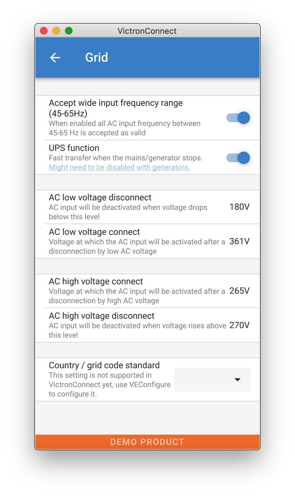 |
10.2.1. Accept wide frequency range
Set the sensitivity of frequency measurement. This setting is used to indicate whether it is necessary for the input frequency to be exactly 50 or 60 Hz. This is a setting that is primarily used in conjunction with generators (speed may not always be stable) to prevent the Multi from rejecting the input supply.
10.2.2. UPS Function
Determines whether the Multi should be critical of the distortion in the supply waveform.
If UPS Function is deselected, this automatically activates the function preventing the lower voltage limit from being exceeded with heavy start-up loads! (previously labeled ‘Allow inrush current’)
10.2.3. AC Voltage Connection and Disconnection
Voltage limits at which feedback relay opens/closes.
These are the limits at which the unit will accept or reject the supply. If the input voltage drops below the set value of the lower limit, the charger output will be reduced to the minimum to prevent further reduction of the voltage.
10.2.4. Country / grid code standard
Grid code setting is not yet available in VictronConnect. Depending on the installation and regional requirements you may need to need to use VEConfigure to adjust additional settings.
10.3. Inverter
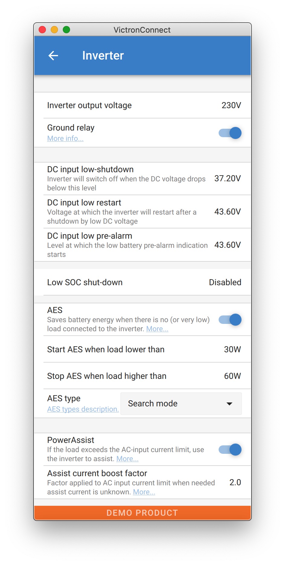 |
10.3.1. Inverter output voltage
This is normally 120/230 Vac.
10.3.2. Ground Relay
Used to enable/disable the internal ground relay functionality. Connection between N and PE during inverter operation.
The ground relay is useful when an earth-leakage circuit-breaker is part of the installation. When the internal transfer switch is open (inverter mode) the Neutral of the inverter is connected to PE. When the transfer switch closes (AC input is transferred to the output) the Neutral is first disconnected from PE. Warning: Disabling the ground relay on "120/240V" models (split phase models) will disconnect the L2 output from the inverter.
10.3.3. DC input low-shutdown
To set the low battery voltage level at which the inverter shuts off. To ensure long battery life, this value should be set according to your battery manufacturer specification.
10.3.4. DC input low restart
To set the voltage at which the inverter restarts after low voltage shut-down. To prevent rapid fluctuation between shut-down and start up, it is recommended that this value be set at least one volt higher than the low battery shut-down voltage.
10.3.5. DC input low pre-alarm
DC input low pre-alarm With this setting one can determine the level at which the Low batter pre-alarm indication starts. Note that in fact the parameter which is changed is an offset voltage relative to the DC input low restart level which in its turn is relative to the DC input low shut-down level. The result of this is that, when changing either one of DC input low restart and DC input low shut-down, this "DC input low pre-alarm" level changes also!
10.3.6. Low SOC shut-down
If the Multi is set to have State of Charge enabled, you can use this feature to shut it down when it reaches the set level. This can be useful on systems where battery voltage does not give a good indication of battery level.#
10.3.7. AES
Energy saving setting to conserve power if there is no significant load drawn from the inverter.
If the system has consumers with high inrush characteristics (such as microwave ovens and air-conditioning) deactivate AES to prevent them from switching on too slowly and causing overload
10.3.8. PowerAssist
Use PowerAssist to prevent an external AC input circuit breaker to trip due to excessive load. If the load exceeds the AC input current limit the Multi will start inverting in parallel with the external AC supply and will provide the extra current needed. Note: When PowerAssist is enabled there is a minimum AC input current limit depending on the device type. Setting a lower limit than this minimum will result in the minimum limit. Note that in a parallel system this limit is per device!
10.3.9. Assist current boost factor
This value is normally set to 2. This is a safe value because any small peak will be compensated by the inverter and the excessive power will not overload the input circuit protection. Be very careful with this setting and change it only once you have carefully considered the possible negative aspects of doing so!
10.4. Charger
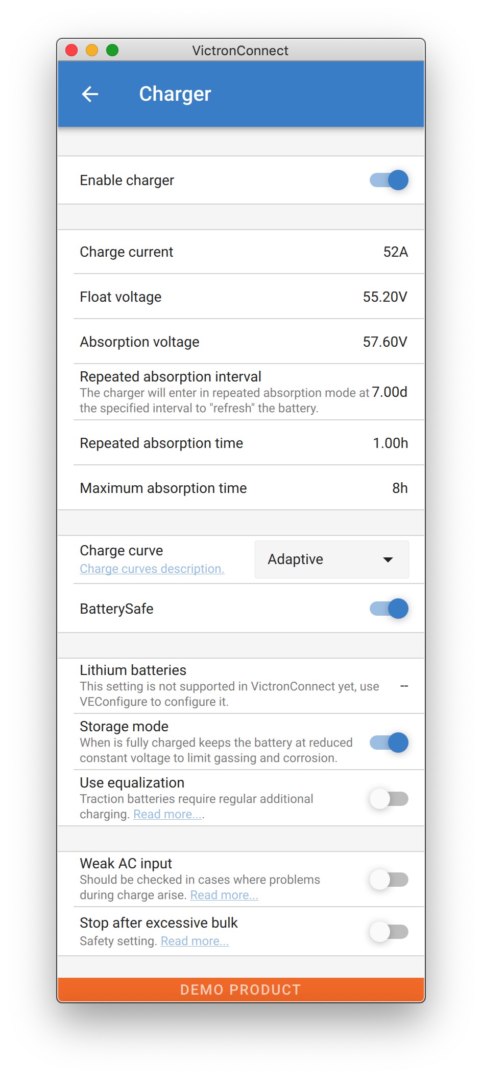 |
10.4.1. Enable charger
When the 'Enable charger' switch is turned off, the Multi's inverter and assist functions will continue to operate, but it will no longer charge; the charging current will be zero.
Disabling charge functionality will mean 100% self-consumption; you may wish to do this when a large enough solar array is connected, and it is expensive to charge the batteries from the grid.
Lead-acid batteries have a low charge efficiency. About 20% of the energy used to charge them is lost in the form of heat. Some installers therefore prefer to disable the Multi's charger functionality and only charge with solar.
When the charger functionality is disabled and the Multi is accepting the grid, it will supply the loads with grid power, but will not charge the batteries. The batteries will only receive charge from the MPPT charge controllers.
In this type of system it is very important to have a large enough solar array. It is also important that the 'Connect when battery voltage drops below' setting in the AC input control menu of VictronConnect is set high enough to ensure that the battery has some extra charge left should there be a blackout.
Warning
Incorrect system design can cause battery damage. Disabling the charger is only recommended in systems that have excess solar power. If the batteries get empty during the night, the system cannot be recovered unless you connect an external battery charger.
10.4.2. Charge current
Use this setting to specify the current with which the battery is charged during the bulk phase. Note that the actual charge current depends on other conditions also. Therefore it is possible that the actual charge current is lower than this setting. This can, among others, be due to a low AC input current limit in combination with a high load; high environmental temperature; too high ripple voltage due to improper cabling. For lead batteries, the charging current should be approximately 10 to 20% of the battery capacity. Also keep in mind the DC consumption that is expected in the system.
10.4.3. Float voltage
Use this setting to specify the Float voltage. Float stage is reduced voltage from absorption, used to trickle in current to finish battery charge without creating excess heat or gassing.
10.4.4. Absorption voltage
Use this setting to specify the Absorption voltage. Absorption is the charge phase where the battery is held at continuous target voltage with variable current.
10.4.5. Repeated absorption interval
Use this setting to specify the interval between repeated absorptions.
10.4.6. Repeated absorption time
Specify the duration of the repeated absorption "pulses".
10.4.7. Maximum absorption time
If the charge curve is fixed then this setting is used to determine the absorption time. In all other cases this setting determines the maximum absorption time.
10.4.8. Charge curve
Under normal circumstances always select the adaptive mode. If the balance between the charger and battery is not ideal, it may be better to choose fixed mode otherwise the voltage will rise too quickly or too slowly and the battery may be over or under charged as a result.
10.4.9. BatterySafe
BatterySafe curve has a special regulation in the absorption phase. The absorption phase will start when the voltage reaches 14.4V (for a 12V battery) regardless of the specified absorption voltage. During the absorption phase the voltage will increase with a fixed ramp until the voltage reaches the absorption voltage or until the calculated absorption time is over. In the latter case the absorption phase will end before the absorption voltage is reached.
In a lead acid battery the charge process isn't always perfectly spread throughout the battery so therefore it can happen that when charging fast (at the limit of what the battery can handle voltage wise), a part of the battery is already "charged" while other parts still have the ability to absorb energy. When the charger is going "full power" to the setpoint voltage to enter absorption the change is quite realistic that a part of the battery is getting overcharged.
BatterySafe reduces the charge current when the voltage is approaching the setpoint to enter absorption. Therefore the battery gets a longer lifetime.
Same as for Adaptive (when the absorption period is calculated from the time the charger is in the Bulk phase), it helps extend the lifespan of the battery.
In general, beware that the wish to charge "as fast as possible" often results in a shorter lifespan of the (lead acid) battery. Taking it a bit slower will indeed cost fuel/time but will pay itself back in battery lifetime. Charging the battery with the generator is most efficient in the 50-80% SOC range. So have this done daily and only go to 100% weekly as then the battery monitor is synced and the battery gets a needed full charge.
10.4.10. Lithium battery mode
Checkbox function
The table below shows the effect of Enabling or Disabling Lithium battery mode:
Feature | Lithium mode Disabled (default) | Lithium mode Enabled |
|---|---|---|
Temperature compensation | Lead algorithm | No temperature compensation |
Re-bulk voltage | 1.3V less than Float-voltage, to a maximum of 12.9V | 0.2V less than Float-voltage, to a maximum of 13.5V |
Note: All mentioned voltages and thresholds are for a 12V system. For 24 multiply by two; and for 48V, multiply by four. So for example at 48V, the re-bulk mechanism for a lithium battery will use Vfloat - 0.8V with a maximum of 54V.
Temperature compensation Charge voltage are not increased or decreased within normal temperature ranges (5°C - 40°C) for lithium batteries. Enabling Lithium mode will disable the normal built-in temperature compensation features that are used for lead acid batteries.
Re-bulk voltage The Re-bulk voltage is the point that the charger returns to the bulk charging stage. It depends upon the float voltage. Lithium batteries tend to have a more stable voltage output and a narrower voltage range than lead acid batteries, so in lithium mode the value between float and re-bulking is reduced.
Required setting per lithium type
A) Batteries with built-in BMS
Batteries with built-in BMS, including charge and discharge interruptors, such as the Victron Superpack, Battleborn or Simplify battery brands. Also known as 'drop-in replacement' type batteries. For these types, enable the lithium battery mode; and set the charging voltages as per the battery manual. There is no need for Assistants or other configuration.
B) Victron V12.8 and 25.6V batteries, requiring a VE.Bus BMS
These require additional configuration that is not currently supported by VictronConnect. Please use VEConfigure instead and install the VE.Bus BMS Assistant, as well as check the Lithium battery checkbox.
C) Intelligent batteries, connected to a GX-device with DVCC enabled:
Checking or not checking the box doesn’t matter; it has no effect. In systems with such a battery, all charger settings are overridden by parameters coming from the CAN-bus.
Examples are Victron 24V Lithiums with a Lynx BMS, BYD, Pylontech, MG Energy Systems, Freedomwon, Redflow, and others.
10.4.11. Storage mode
With this feature active, after 24 hours in float charge, the charging voltage will be reduced below the float voltage to provide optimum protection of the battery against overcharging; charging current will continue to be applied regularly to compensate for self-discharge. This is the rest voltage if the battery is fully charged.#
10.4.12. Use equalisation
For optimum charging, special traction batteries require a fixed charging current phase in addition to a voltage curve. Beware that this often results in a higher charging voltage that can be damaging to DC loads!
10.4.13. Weak AC input
If the quality of the supply waveform is less than the charger expects, it will reduce its output to ensure that the COS phi (difference between current/voltage phases) remains acceptable. This protection can be deactivated for low capacity or poorly regulated power supplies.
10.4.14. Stop after excessive bulk
If the absorption voltage has not been reached after 10 hours, the battery may be faulty and the charger will switch off for safety reasons. This setting will trigger the lithium battery options and wizard, depending on the configuration of your lithium battery and manufacturers advice you may need to adjust additional settings as well.
10.5. AC Input Control
The AC Input Control can be set up in numerous ways, for example, the Multi will disconnect from the grid when the batteries are full enough and/or the AC load is not too big. The Multi will disconnect from the grid most of the time. It will only let the grid in when the batteries are empty or when you are running a big AC load. You now can use the grid like you would use a backup generator.
The mechanism behind the AC Input Control is the opening or closing the Multi’s internal AC input relay.
This feature in not enabled by default.
The normal function of this relay is to open as soon as the grid or generator is not there. For example, during a blackout or when a generator is off. This is a safety action. The relay prevents energy feeding into the grid during a blackout or when the generator is off.
This relay can also be setup to purposefully ignore the grid. It will still perform its normal safety action but it can open and disconnect from the grid under more situations. It can ignore the grid when the batteries are still full enough. Now DC solar power can be prioritized and the grid will be used like a backup generator
10.5.1. When can the grid be controlled?
The AC input relay can be programmed to selectively ignore the grid, while looking at two parameters: It can look at battery voltage and/or at AC load parameters.
The grid is ignored when the batteries are full enough. The grid is let in when the batteries are empty:
This setting can be used to charge the batteries from the grid should the batteries get too empty. This can occur, for example, at night or during a long period of bad weather.
In this scenario the Multi will look at the battery voltage. It will let the grid in when the battery voltage is too low, for a certain amount of time. It will ignore the grid as soon as the battery voltage has increased above a certain level, for a certain amount of time.
The multi can also disconnect the grid on battery state of charge.
The grid is ignored when the AC loads are low. The grid is let in when the AC loads are high:
This setting can be used to allow grid in when the AC load is higher than the Multi rating. This will prevent the Multi going into overload. This setting can also be used for large loads that you do not want to run from the battery.
In this scenario the Multi will look at the AC load. As soon as it sees that the load is above a certain level, for a certain amount of time, the Multi will let the grid in. The Multi will stop letting the grid in as soon as it sees that the AC load has dropped below a certain level, for a certain amount of time.
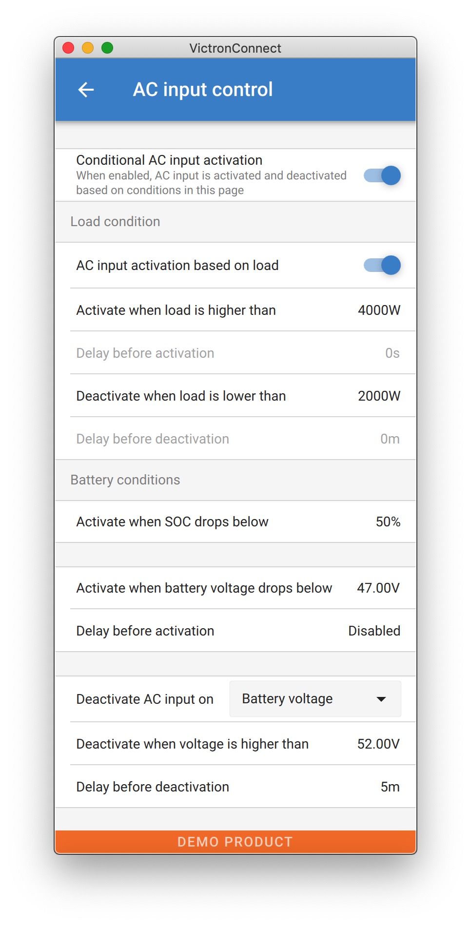 |
10.5.2. Conditional AC input activation
Enables the use of AC Input Control to modify the operation of the feedback relay.
10.5.3. Load Conditions
This setting can be used to allow grid in when the AC load is higher than the Multi rating. This will prevent the Multi going into overload. This setting can also be used for large loads that you do not want to run from the battery.
In this example the grid will not be ignored when the load exceeds 4000 Watts, with no delay.
Do not ignore AC input means that the grid is accepted because the AC input relay is closed. The grid will be ignored when the load drops below 2000 W.
Ignore AC means that the grid is ignored because the AC input relay is open.
Depending on your load, if the AC input relay is opening and closing frequently, add a time delay before activation and deactivation.
AC input activation based on load
Activate when load is higher than W
Delay before activation T
Deactive when load is lower than W
Delay before deactivation T
10.5.4. Battery Conditions
This setting can be used to charge the batteries from the grid should the batteries get too empty. This can occur, for example, at night or during a long period of bad weather.
In this example, the grid is not ignored when the battery voltage is less than 47 Volt. Do not ignore AC input means that the grid is accepted because the AC input relay is closed.
The grid will be ignored again when the battery voltage exceeds 52 Volts for more than 5 minutes.
Ignore AC means that the grid is ignored because the AC input relay is open. Apart from “battery voltage”, there are two other options to choose from: “bulk finished” or “absorption finished”.
Choosing “absorption finished” is a good way to ensure the batteries are getting a full charge every now and then. But it can lead to a higher electricity bill. The absorption charge stage of a lead-acid battery is much less efficient than the bulk stage.
This could be a reason to choose the “bulk finished” option. At the end of the bulk charge stage a lead-acid battery is about 85% full.
For more information about bulk and absorption please see the Victron Energy book “Energy Unlimited”, page 25. Follow this link: https://www.victronenergy.com.au/orderbook
It is also possible to let grid in when the batteries fall below a certain state of charge.
Important
In a system that contains additional charge sources external to the Multi, or DC loads, the “state of charge” option should only be used if you also have a GX device in the system. And the GX device is connected to both the Multi and the external MPPT solar charger(s) and/or a BMV battery monitor. See this link for more information: https://www.victronenergy.com/media/pg/CCGX/en/configuration.html#UUID-3d1bea6f-30a0-7d84-8ba6-dab25033ba16