3. Operation
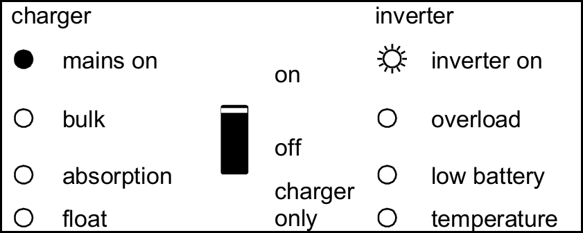
3.1. On/Off/Charger Only Switch
Start procedure:
Before switching the Quattro on, ensure that all AC connections, battery connections, and grounding connections are correctly installed and secured.
The Quattro can be switched on by moving the On/Off switch to the “ON” position.
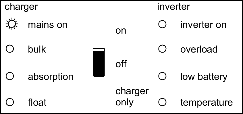
When switched to “on”, the product is fully functional. The inverter will come into operation and the LED “inverter on” will light up.
An AC voltage connected to the “AC in” terminal will be switched through to the “AC out” terminal, if within specifications. The inverter will switch off, the “mains on” LED will light up and the charger commences charging. The “bulk”, “absorption” or “float” LED’s will light up, depending on the charger state.
If the voltage at the “AC-in” terminal is rejected, the inverter will switch on.
When the switch is switched to “charger only”, only the battery charger of the Quattro will operate (if mains voltage is present). In this mode input voltage also is switched through to the “AC out” terminal.
Note
When only the charger function is required, ensure that the switch is switched to “charger only”. This prevents the inverter from being switched on if the mains voltage is lost, thus preventing your batteries from running flat.
Switch-off procedure:
To switch the inverter off, move the On/Off switch to the “OFF” position.
When switched off, the inverter will stop all internal functions.
Warning
Even after the switch is turned OFF, hazardous AC voltage may still be present at the AC-IN terminals if an external AC source is connected. Do not touch the AC-IN terminals unless the external AC supply has been fully isolated and verified as de-energised.
3.2. Remote control
Remote control is possible with a 3-way switch or with a Multi Control panel.
The Multi Control panel has a simple rotary knob with which the maximum current of the AC input can be set: see PowerControl and PowerAssist in Section 2.
3.3. Equalisation and forced absorption
3.3.1. Equalisation
Traction batteries require regular additional charging. In the equalisation mode, the Quattro will charge with increased voltage for one hour (1 V above the absorption voltage for a 12 V battery, 2 V for a 24 V battery), and with charging current limited to 1/4 of the set value.
The “bulk” and “absorption” LED’s flash alternately.
Warning
Equalisation mode supplies a higher charging voltage than most DC consuming devices can cope with. These devices must be disconnected before additional charging takes place.
3.3.2. Forced absorption
Under certain circumstances, it can be desirable to charge the battery for a fixed time at absorption voltage level. In Forced Absorption mode, the Quattro will charge at the normal absorption voltage level during the set maximum absorption time.
The “absorption” LED lights.
3.3.3. Activating equalisation or forced absorption
The Quattro can be put into both these states from the remote panel as well as with the front panel switch, provided that all switches (front, remote and panel) are set to “on” and no switches are set to “charger only”. In order to put the Quattro in this state, the procedure below should be followed.
If the switch is not in the required position after following this procedure, it can be switched over quickly once. This will not change the charging state.
Note
Switching from “on” to “charger only” and back, as described below, must be done quickly. The switch must be toggled such that the intermediate position is 'skipped', as it were. If the switch remains in the “off” position even for a short time, the device may be turned off. In that case, the procedure must be restarted at step 1. A certain degree of familiarisation is required when using the front switch on the Compact in particular. When using the remote panel, this is less critical.
Procedure:
Check whether all switches (i.e. front switch, remote switch or remote panel switch if present) are in the “on” position.
Activating equalisation or forced absorption is only meaningful if the normal charging cycle is completed (charger is in 'Float').
To activate:
Switch rapidly from “on” to “charger only” and leave the switch in this position for ½ to 2 seconds.
Switch rapidly back from “charger only” to “on” and leave the switch in this position for ½ to 2 seconds.
Switch once more rapidly from “on” to “charger only” and leave the switch in this position.
On the Quattro (and, if connected, on the MultiControl panel) the three LED’s “Bulk”, “Absorption” and “Float” will now flash 5 times.
Subsequently, the LED’s “Bulk”, “Absorption” and “Float” will each light during 2 seconds.
a. If the switch is set to “on” while the “Bulk” LED lights, the charger will switch to equalisation.
b. If the switch is set to “on” while the “Absorption” LED lights, the charger will switch to forced absorption.
c. If the switch is set to “on” after the three LED sequence has finished, the charger will switch to “Float”.
d. If the switch has not been moved, the Quattro will remain in “charger only’ mode and switch to “Float”.
3.4. LED indications and their meaning
For the latest and most up to date information about the blink codes, please refer to the Victron Toolkit app.
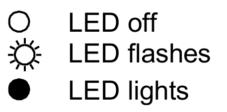
Key to LED states:
 |
Inverter
The inverter is on, and supplies power to the load. |
|
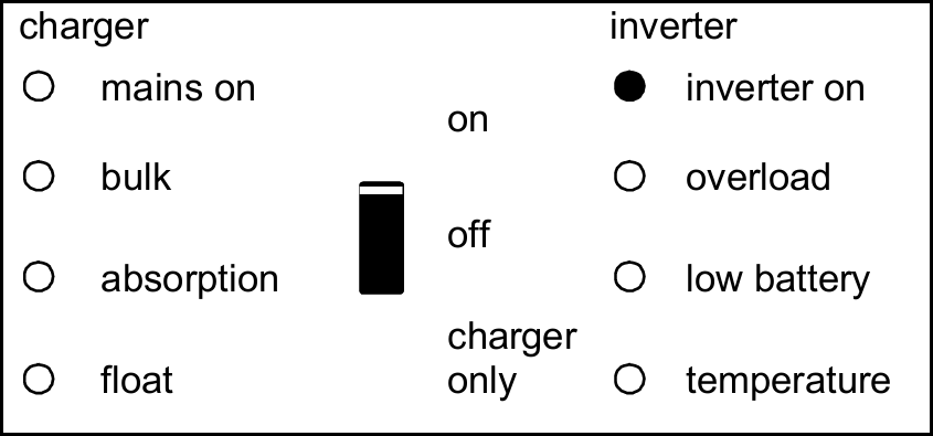
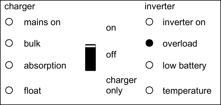
The nominal power of the inverter is exceeded. The “overload” LED flashes. |
|
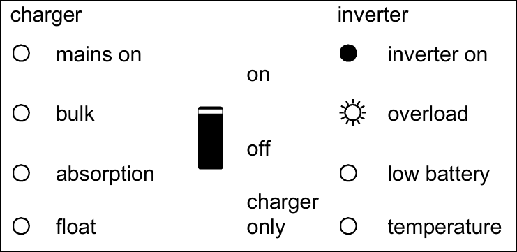
The inverter is switched off due to overload or short circuit. |
|
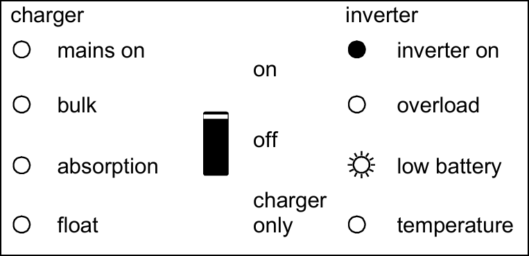
The battery is almost empty. |
|
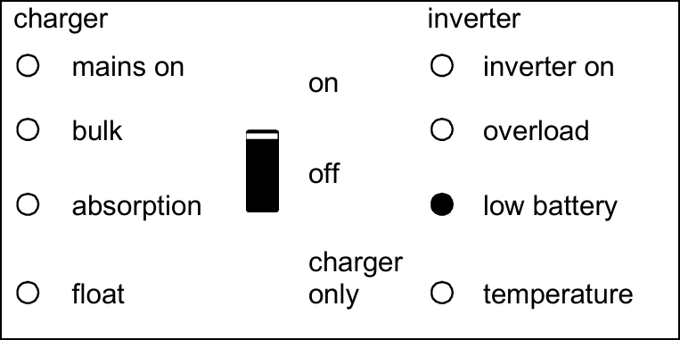
The inverter is switched off due to low battery voltage. |
|
The internal temperature is reaching a critical level. |
|
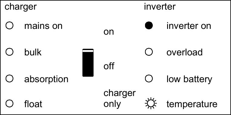
The inverter is switched off due to excessively high internal temperature. |
|
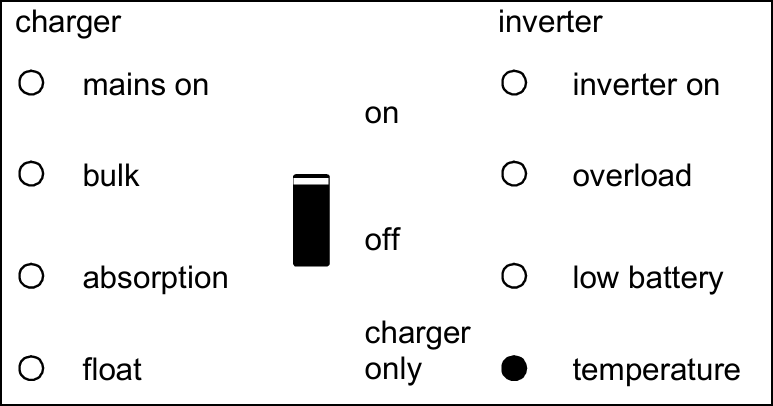
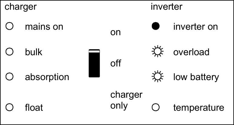
If these LEDs flash alternately, the battery almost empty and nominal power is exceeded. If these flash simultaneously, there is an excessively high ripple voltage at the battery connection. |
|
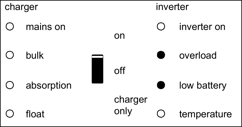
The inverter is switched off due to an excessively high ripple voltage on the battery connection. |
|
Battery charger
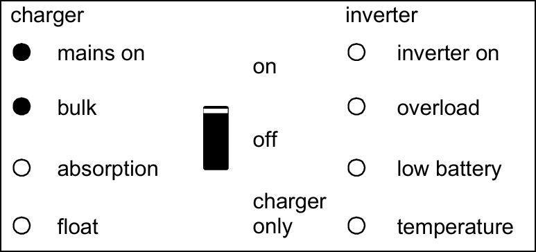
The AC voltage on AC-in-1 or AC-in-2 is switched through, and the charger operates in bulk phase. |
|
The AC voltage on AC-in-1 or AC-in-2 is switched through and the charger operates, but the set absorption voltage has not yet been reached (battery protection mode). |
|
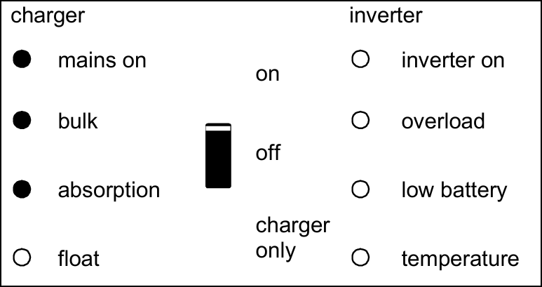
The AC voltage on AC-in-1 or AC-in-2 is switched through, and the charger operates in absorption phase. |
|
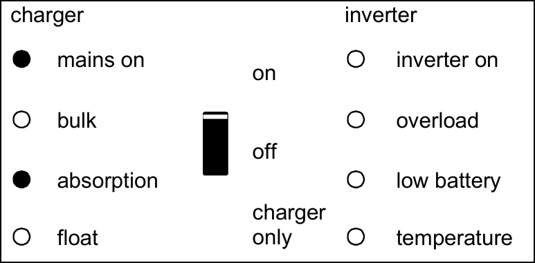
The AC voltage on AC-in-1 or AC-in-2 is switched through, and the charger operates in float or storage phase. |
|
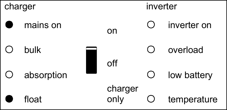
The AC voltage on AC-in-1 or AC-in-2 is switched through, and the charger operates in equalisation mode. |
|
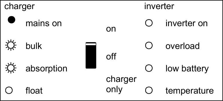
Special indications
Set with limited input current. Occurs only if PowerAssist is disabled. The AC voltage on AC1-in-1 or AC-in-2 is switched through. The AC-input current is equal to the load current. The charger is down-controlled to 0A. |
|
Set to supply additional current. The AC voltage on AC-in-1 or AC-in-2 is switched through, but the load demands more current than the mains can supply. The inverter is now switched on to supply additional current. |
|