11. Appendix
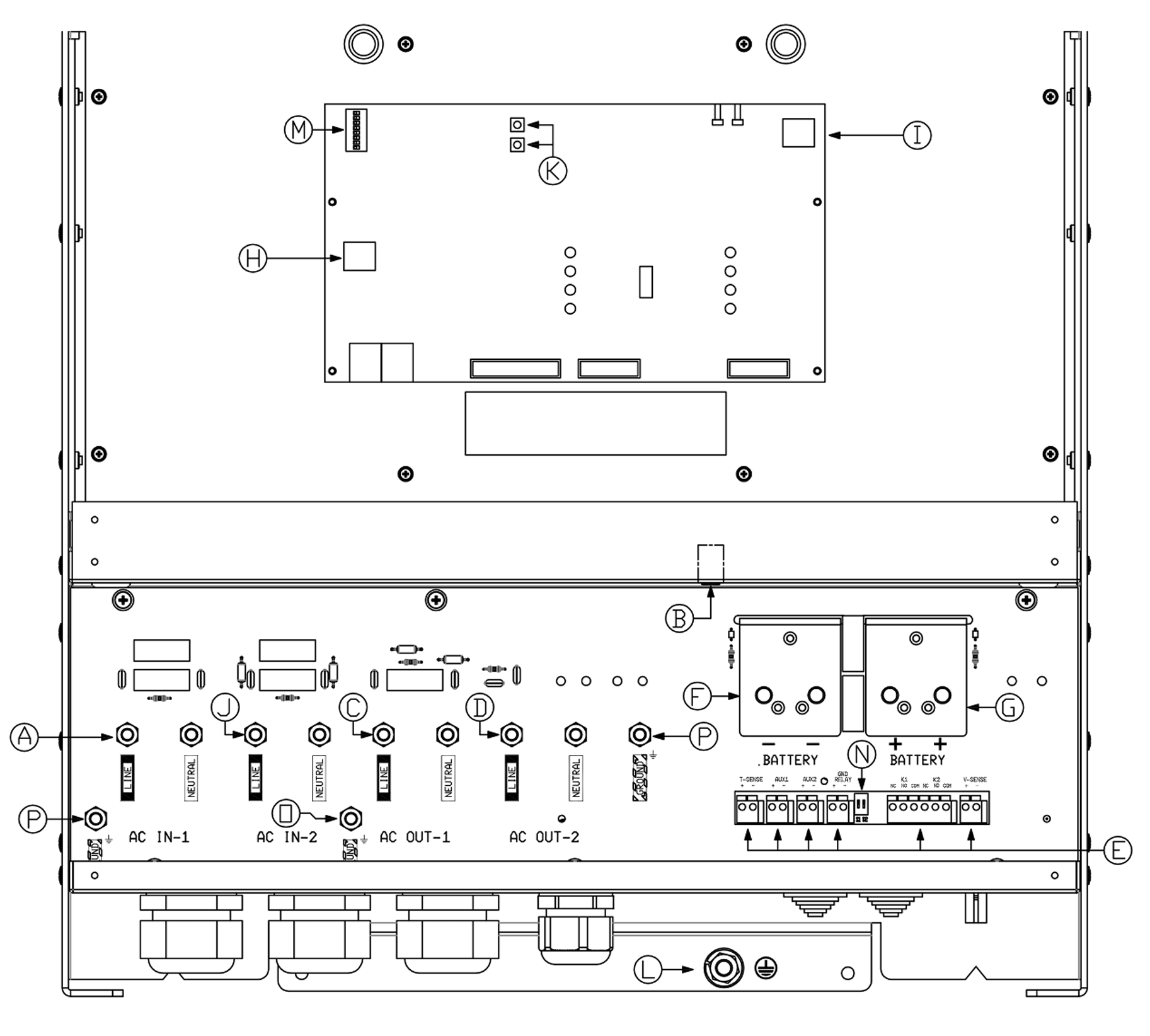
11.1. A: Connection overview
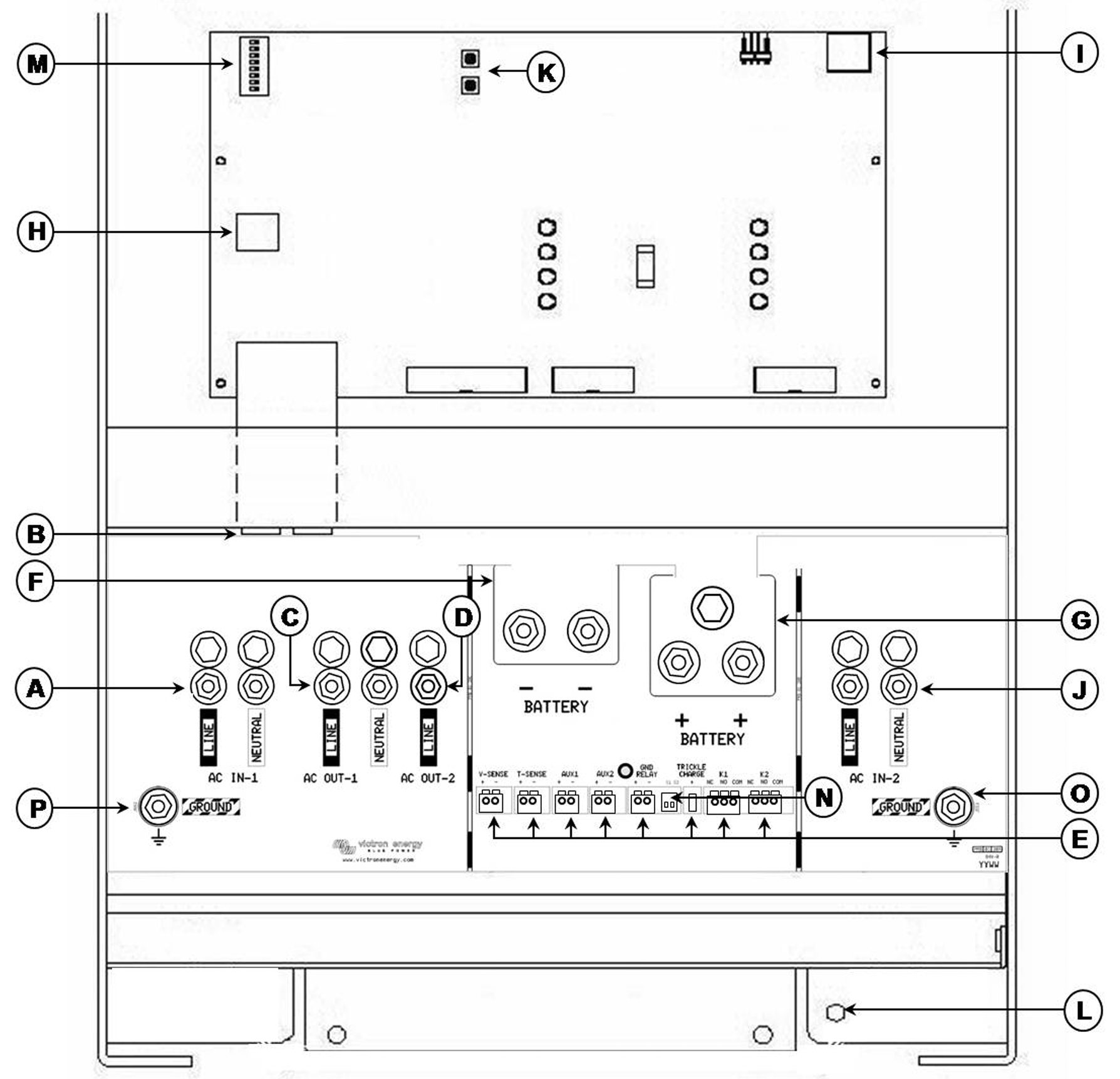
A | AC input M6 (generator input) AC IN-1. Left to right: L (phase), N (neutral). |
B | 2x RJ45 connector for remote panel and/or parallel and 3-phase operation. |
C | AC output M6 AC OUT-1. Left to right: L (phase), N (neutral). |
D | AC output M6 AC OUT-2. Left to right: N (neutral), L (phase). |
E | Terminals for: (left to right) Voltage sense Temperature sensor (can be programmed for a two-signal BMS) Aux input 1 (can be programmed for a two-signal BMS) Aux input 2 (can be programmed for a two-signal BMS) GND-relay Starter battery plus + (starter battery minus must be connected to service battery minus) Programmable relay contacts K1 Programmable relay contacts K2 |
F | Double M8 battery minus connection. |
G | Double M8 battery positive connection. |
H | Connector for remote switch: Short left and middle terminal to switch “on”. Short right and middle terminal to switch to “charger only”. |
I | Alarm contact: Left to right: NC, NO, COM. |
J | AC input M6 (shore/grid supply) AC IN-2. Left to right: L (phase), N (neutral). |
K | Push buttons for set-up mode |
L | Primary ground connection M8 (PE). |
M | DIP switches for set-up mode. |
N | Slide switches, factory setting SW1= off position, SW2 = off position. SW1: Off = internal GND relay selected, On = external GND relay selected (to connect ext GND relay: see E). SW2: No application. To be used for future features. |
O | AC IN-2 M6 common earth connection (ground). |
P | AC IN-1 and AC OUT-1 M6 earth connection (ground). |
5 - 10kVA models
15kVA models
11.2. B: Block diagram
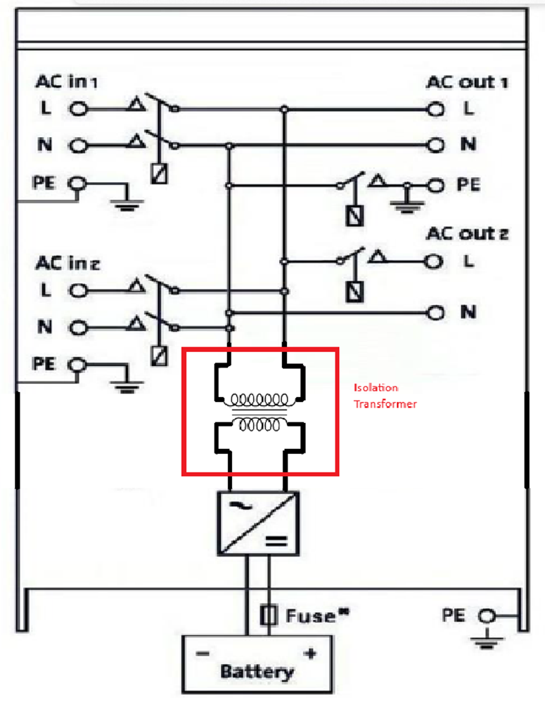 |
* See table in Chapter 4.2 for "Recommended DC fuse".
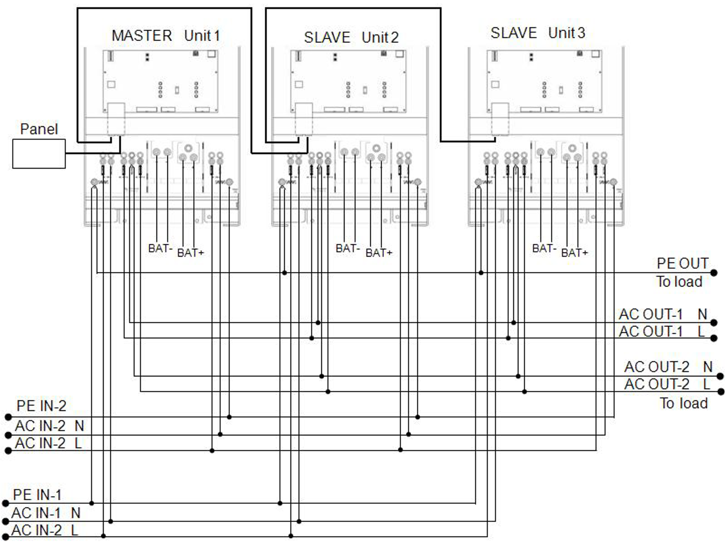
11.3. C: Parallel connection
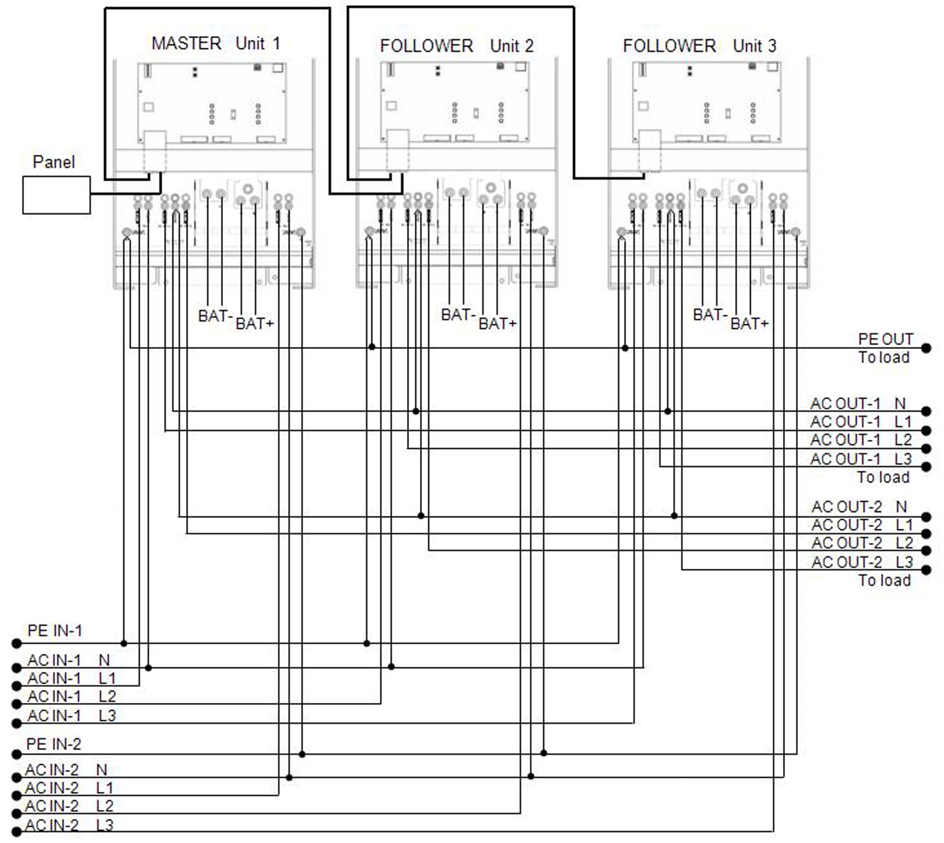
11.4. D: Three phase connection
11.5. E: Charge characteristic
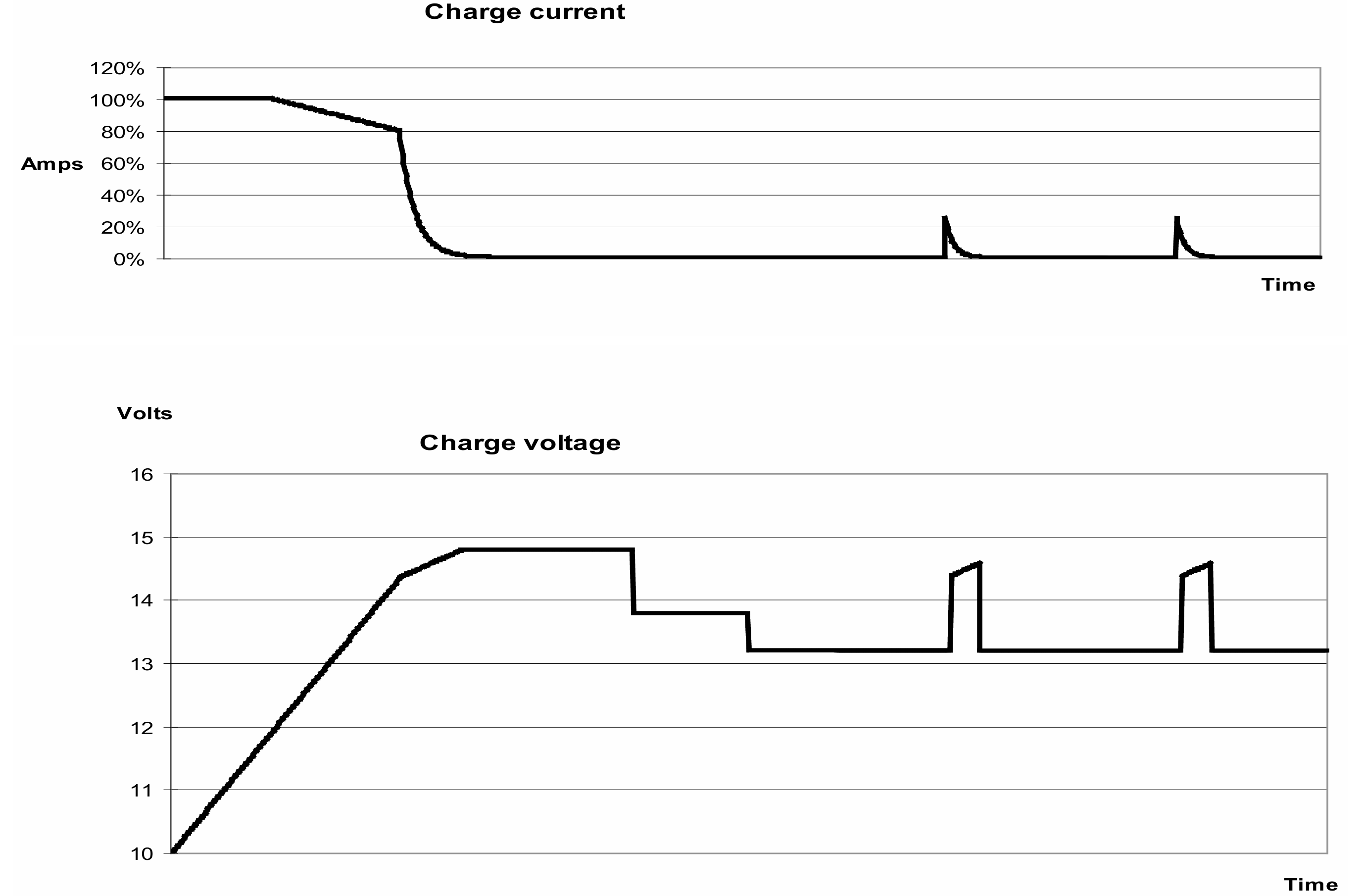
4-stage charging:
Bulk
Entered when charger is started. Constant current is applied until nominal battery voltage is reached, depending on temperature and input voltage, after which constant power is applied up to the point where excessive gassing is starting (14.4 V resp. 28.8 V, temperature-compensated).
Battery Safe
The applied voltage to the battery is raised gradually until the set Absorption voltage is reached. The Battery Safe Mode is part of the calculated absorption time.
Absorption
The absorption period is dependent on the bulk period. The maximum absorption time is the set Maximum Absorption time.
Float
Float voltage is applied to keep the battery fully charged.
Storage
After one day of float charge the output voltage is reduced to storage level. This is 13,2 V resp. 26,4 V (for 12 V and 24 V charger). This will limit water loss to a minimum when the battery is stored for the winter season. After an adjustable time (default = 7 days) the charger will enter Repeated Absorption mode for an adjustable time (default = one hour) to ’refresh’ the battery.
11.6. F: Temperature compensation
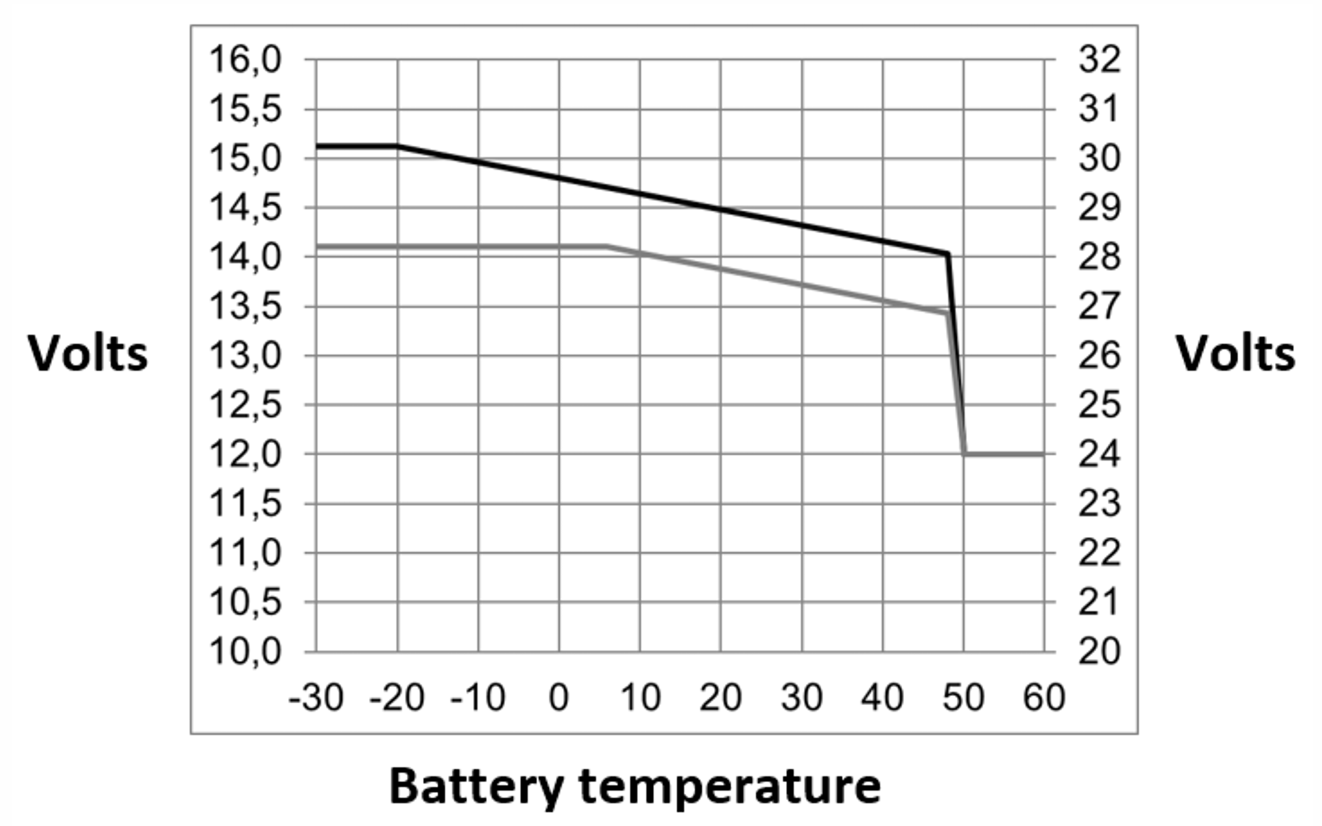
Default output voltages for Float and Absorption are at 25 °C.
Reduced Float voltage follows Float voltage and Raised Absorption voltage follows Absorption voltage.
In adjust mode temperature compensation does not apply.
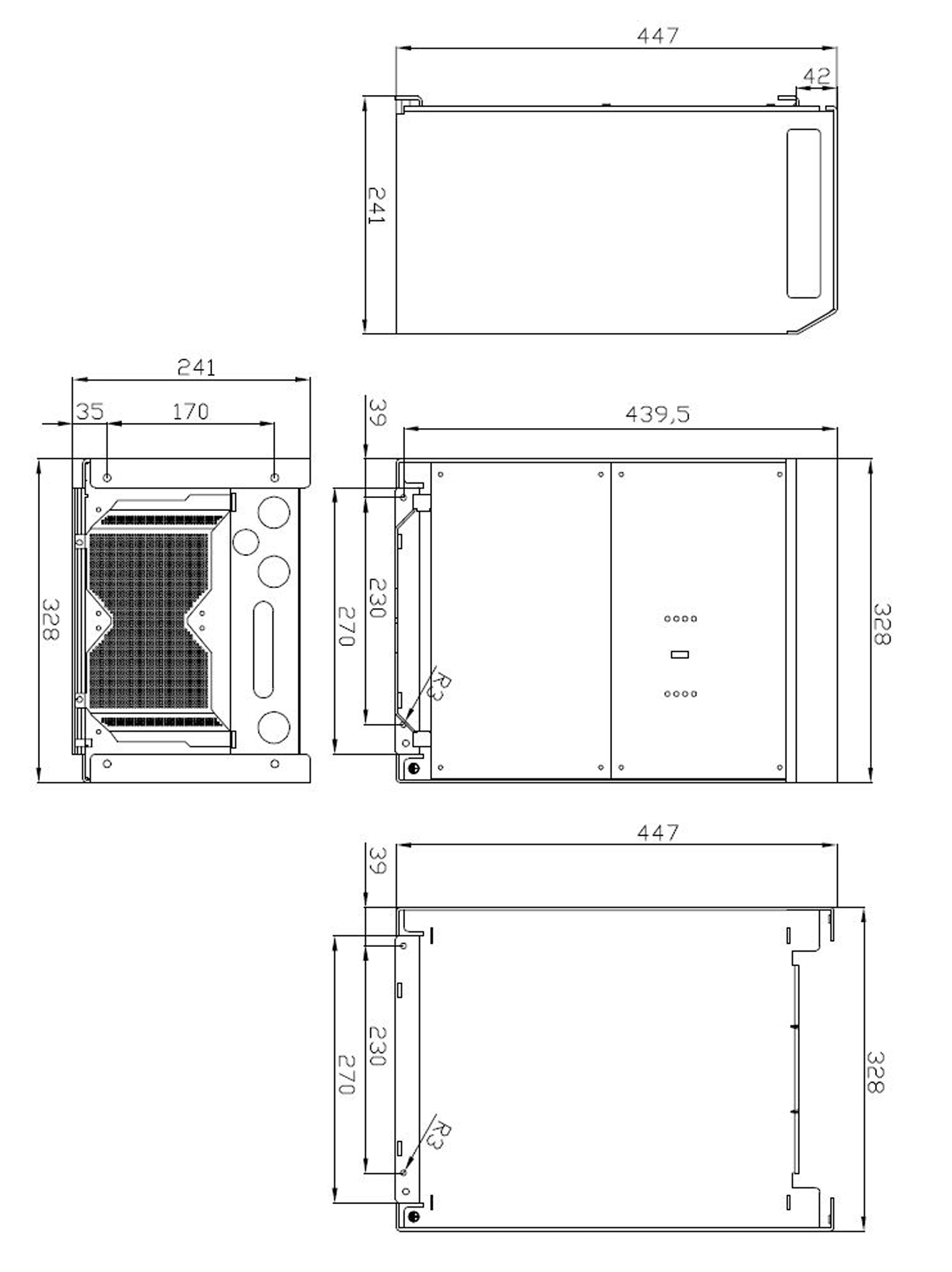
11.7. G: Dimensions
11.7.1. G: Dimensions 12V 5kVA, 24V 8kVA, 48V 8kVA / 10kVA
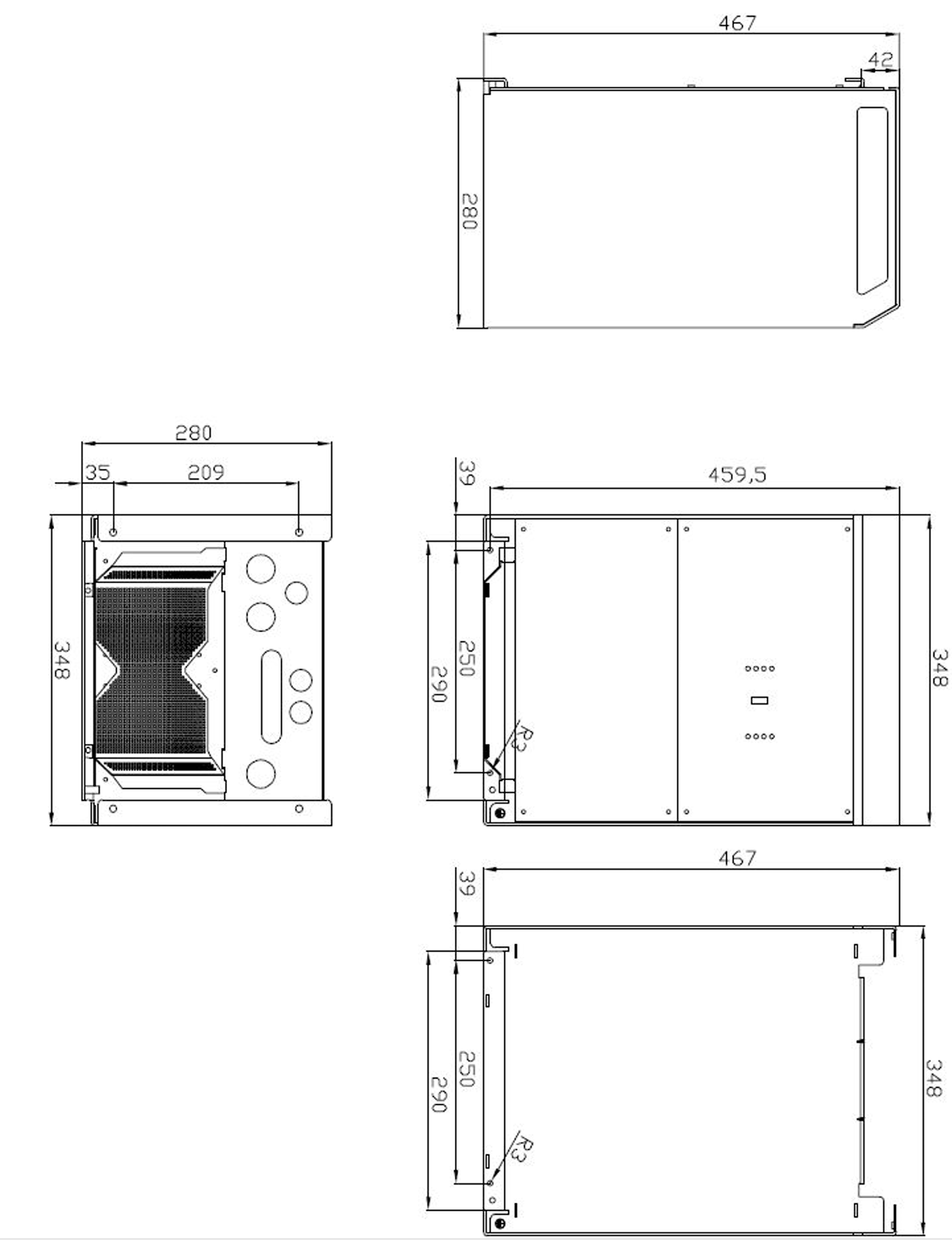
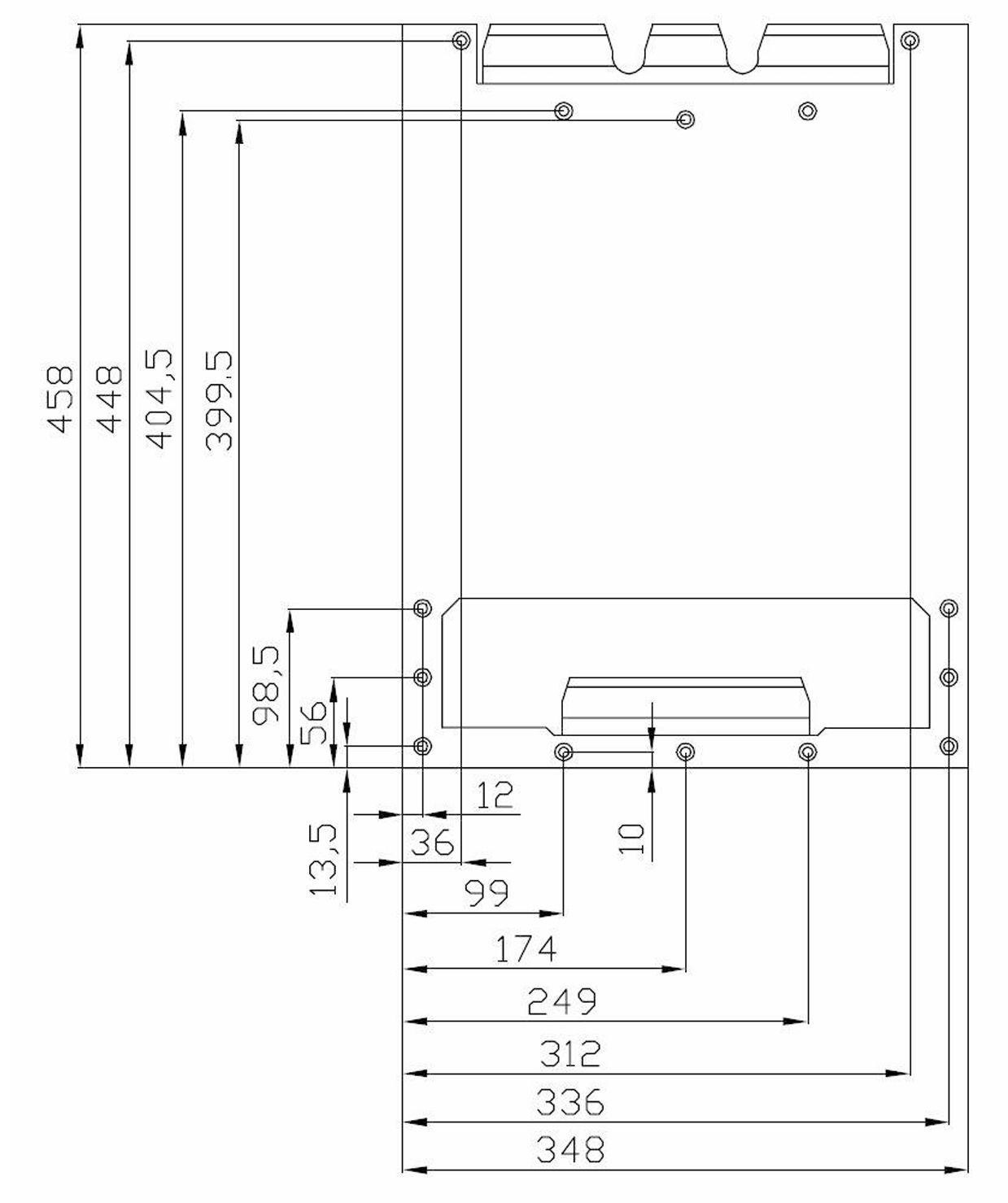
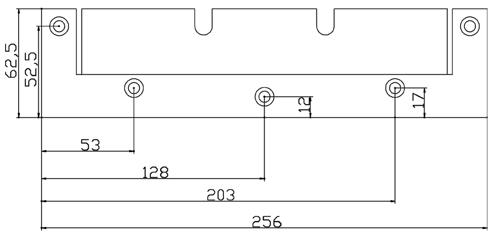
Wall plate
11.7.2. G: Dimensions 24V 5kVA, 48V 5kVA
Wall plate
11.7.3. G: Dimensions 48V 5kVA-S
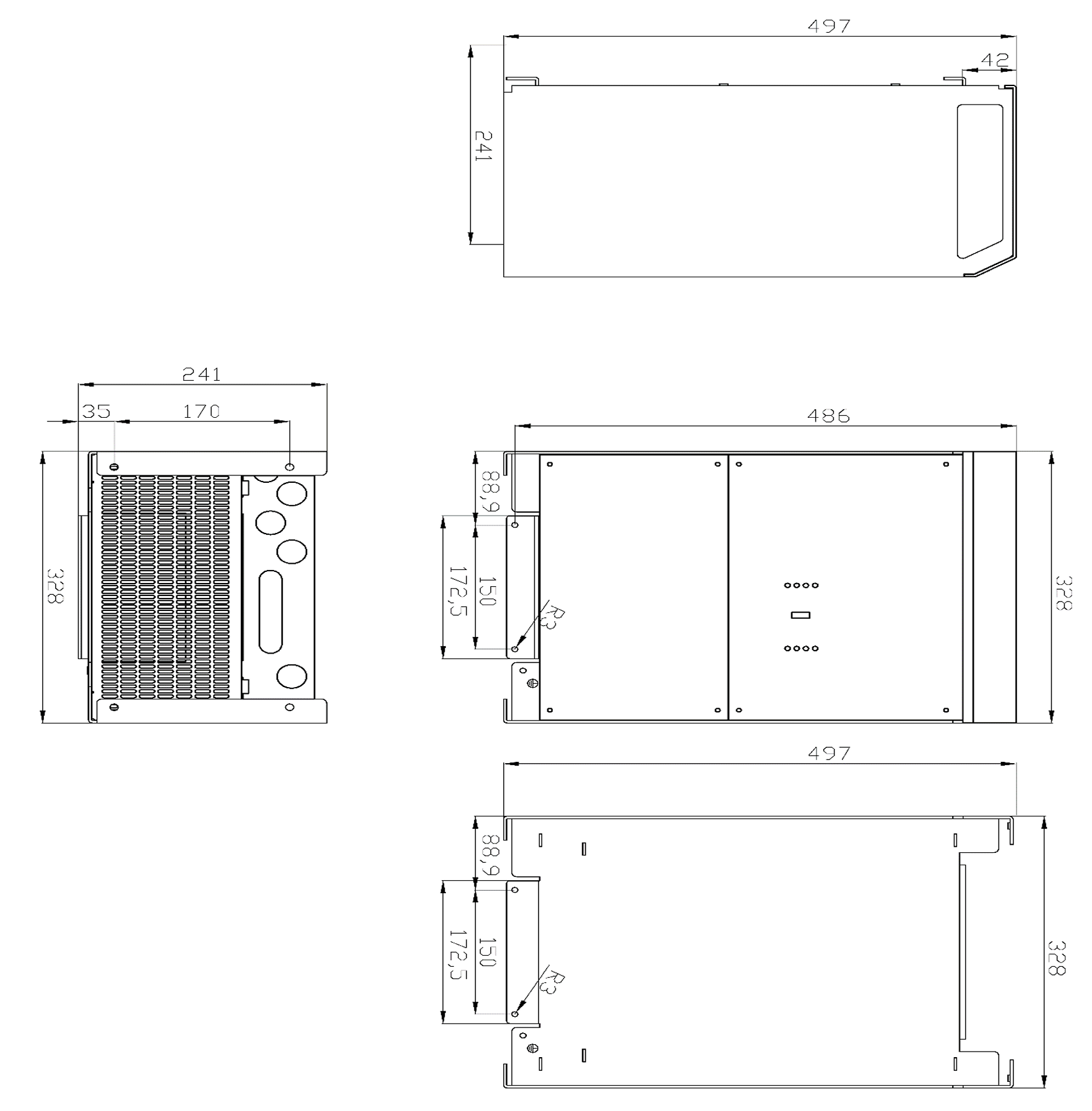
11.7.4. G: Dimensions 15kVA
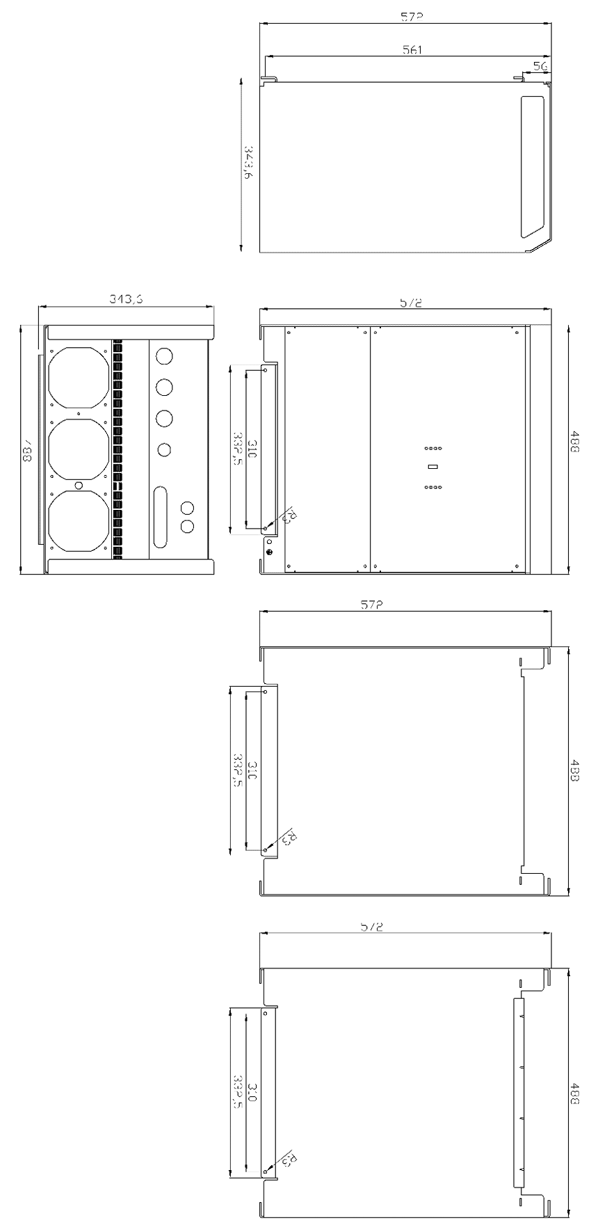 |
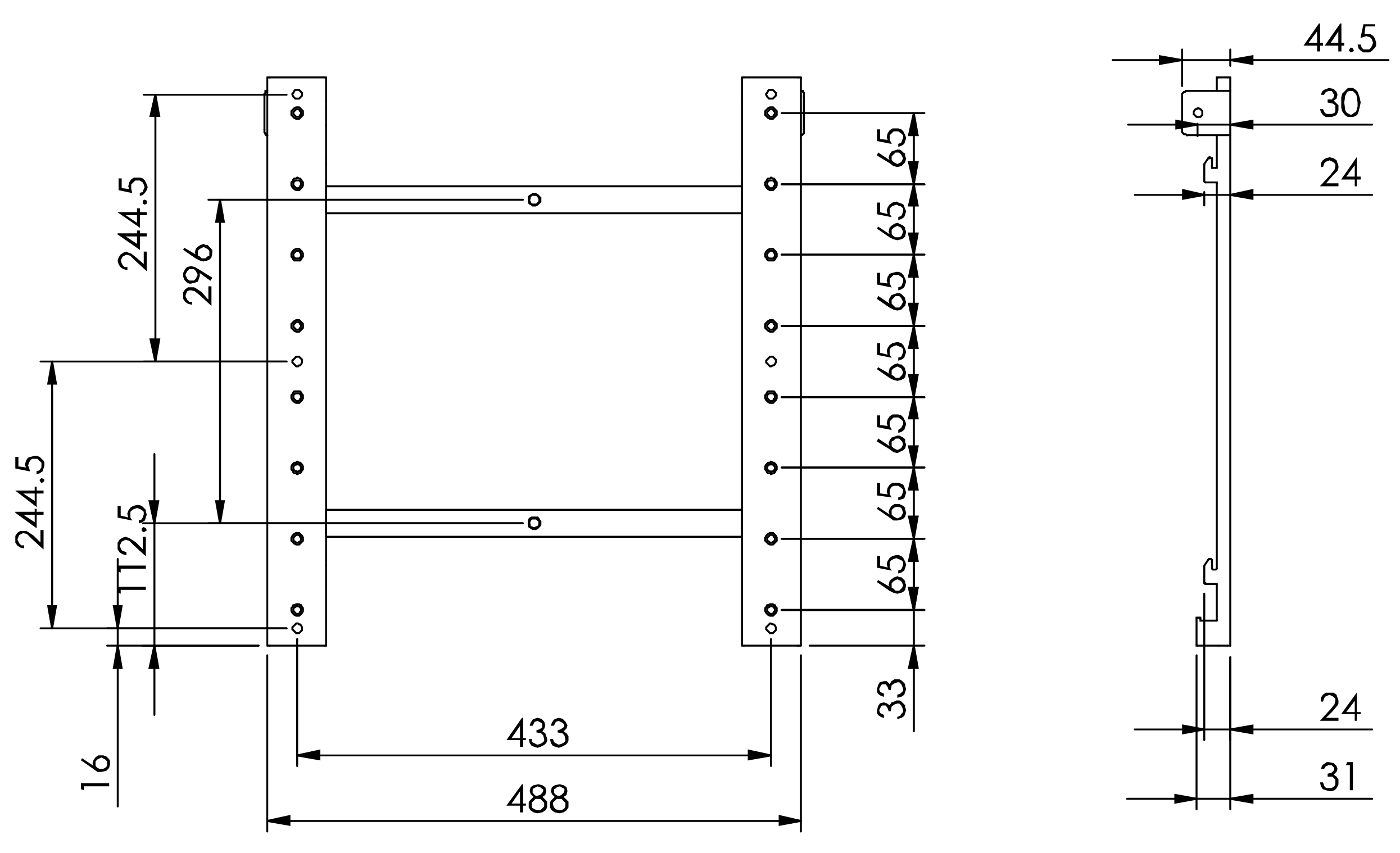
Wall plate
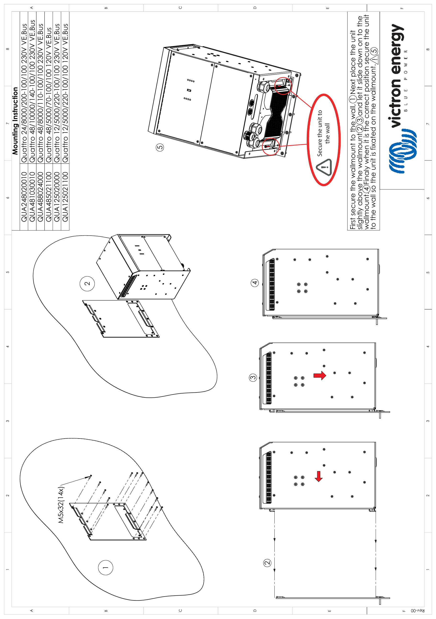
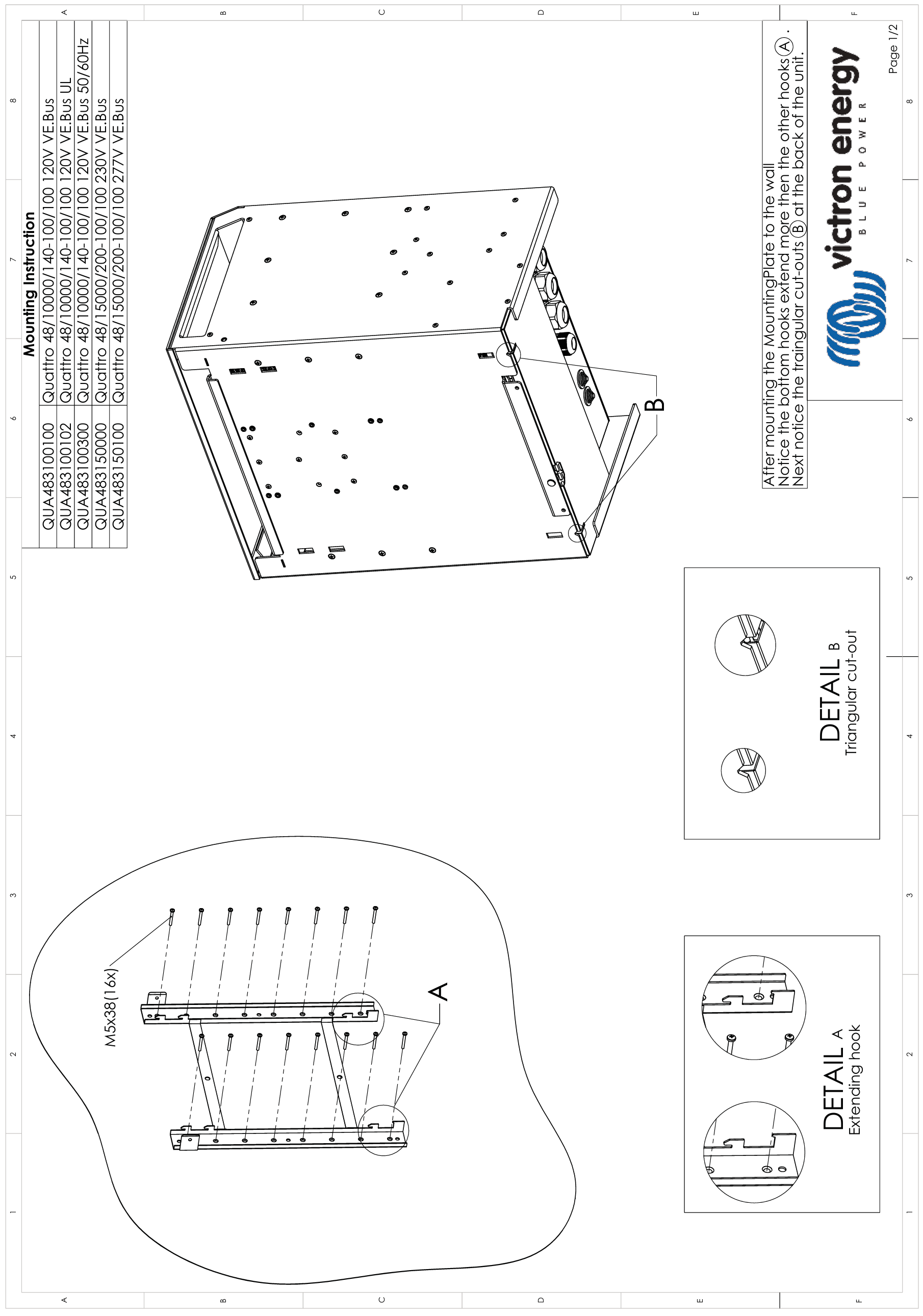
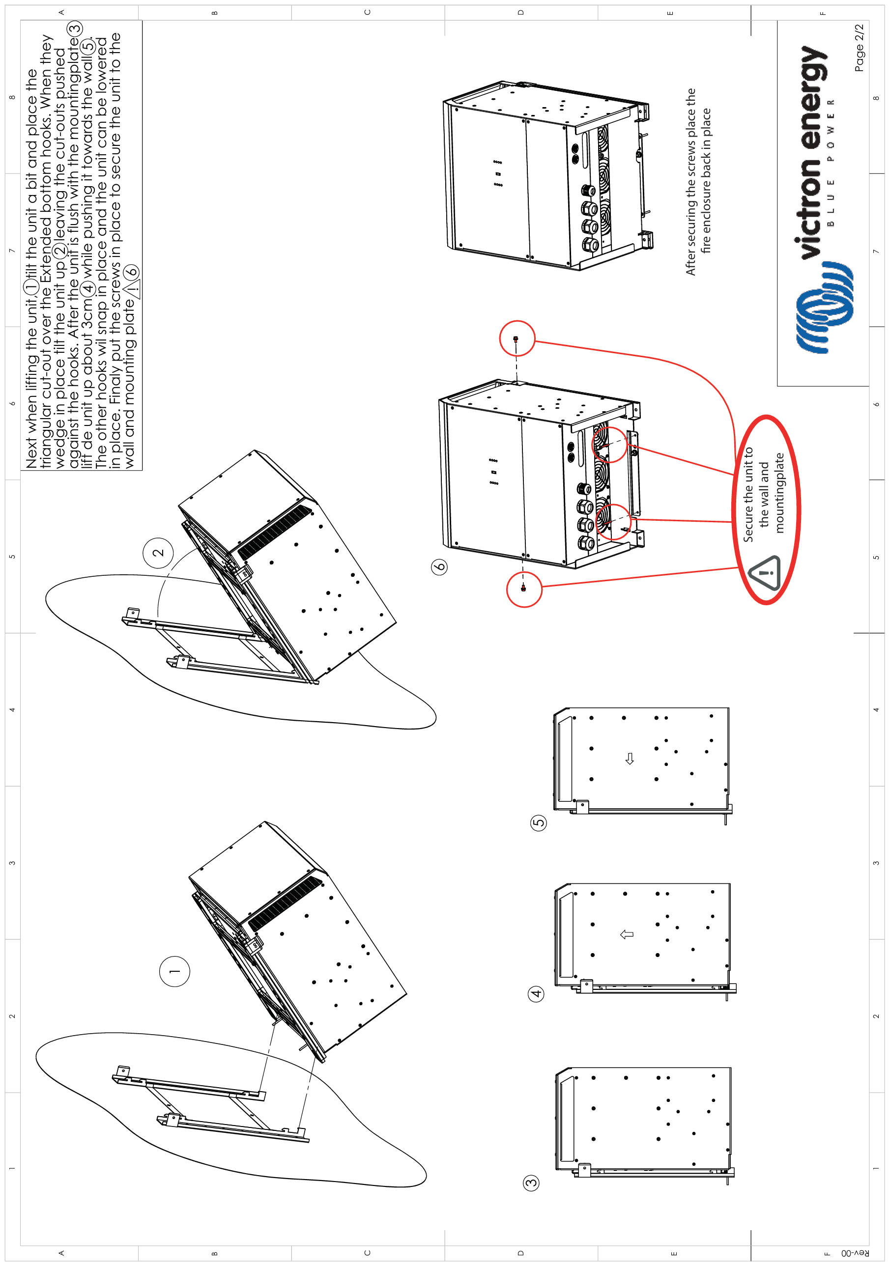
11.8. H: Wall Plate Mounting