4. Installation
Warning
This product may only be installed by a qualified electrician.
Warning
To reduce the risk of injury, charge only Lead Acid or LiFePO4-type rechargeable batteries. Other types of batteries may burst, causing personal injury and damage. Do not try to recharge non-rechargeable batteries.
4.1. Location
The Quattro should be installed in a dry, well-ventilated location, as close as possible to the batteries. The device should be surrounded by a free space of at least 10 cm for cooling purposes.
Warning
The Quattro is rated IP20. Therefore, It must be installed indoors.
Warning
An excessively high environmental temperature has the following consequences:
- shorter lifecycle.
- lower charging current.
- lower peak power or full inverter shut off.
Warning
Never place the device directly above the batteries.
The Quattro is suitable for wall mounting. A solid surface, suitable for the weight and dimensions of the product must be available (e.g., concrete, or masonry). For mounting purposes, a hook and two holes are provided at the back of the casing (see appendix G). The device can be fitted either horizontally or vertically. For optimal cooling, vertical fitting is preferred.
See appendix H for wall plate mounting instructions.
Warning
When integrating inverter/chargers with generators in a single enclosure (hybrid generators), using shock mounts is mandatory. They mitigate damage risk to the inverter/charger by absorbing the generator's operational energy, thus extending component lifespan.
Key criteria for selecting shock mounts include:
Selection is based on the specific generator vibration frequency ranges to be isolated.
The shock mounts must bear the equipment's weight without impairing functionality.
Warning
The inner part of the device should remain well accessible after installation.
The distance between the Quattro and the battery should be as short as possible to reduce voltage loss across the battery leads to a minimum.
Warning
Install the product in a heatproof environment. Ensure therefore that there are no chemicals, plastic parts, curtains or other textiles, etc. in the direct vicinity.
Warning
The Quattro has no internal DC fuse. The DC fuse should be installed outside the Quattro.
4.2. Connecting the battery cables
In order to use the full potential of the Quattro, batteries of sufficient capacity and battery cables with the correct cross-section should be used. To isolate the batteries from the Quattro a disconnect device adequate for the rating should be used.
Model | Battery capacity | DC fuse | Cross-section per positive and negative terminal connection for cables between 0 and 5m *, **, *** | Cross-section per positive and negative terminal connection for cables between 5 and 10m *, **, *** |
|---|---|---|---|---|
12/5000/200 | 800–2400 | 800 A | 2x 120 mm2 | |
24/5000/120 | 400–1400 | 400 A | 2x 50mm2 | 2x 95mm2 |
48/5000/70 | 200–800 | 200 A | 1x 70mm2 | 2x 70mm2 |
24/8000/200 | 400–1400 | 500 A | 2x 70mm2 | 2x 120mm2 |
48/8000/110 | 200–800 | 300 A | 2x 50mm2 | 2x 95mm2 |
48/10000/140 | 250 - 1000 | 400 A | 2x 50mm2 | 2x 95mm2 |
48/15000/200 | 400 - 1500 | 600 A | 2x 95mm2 | 2x 150mm2 |
* Follow local installation rules.
** Do not locate battery cables in a closed conduit.
*** “2x” means two positive and two negative cables.
Connection procedure
Onsite wiring is required.
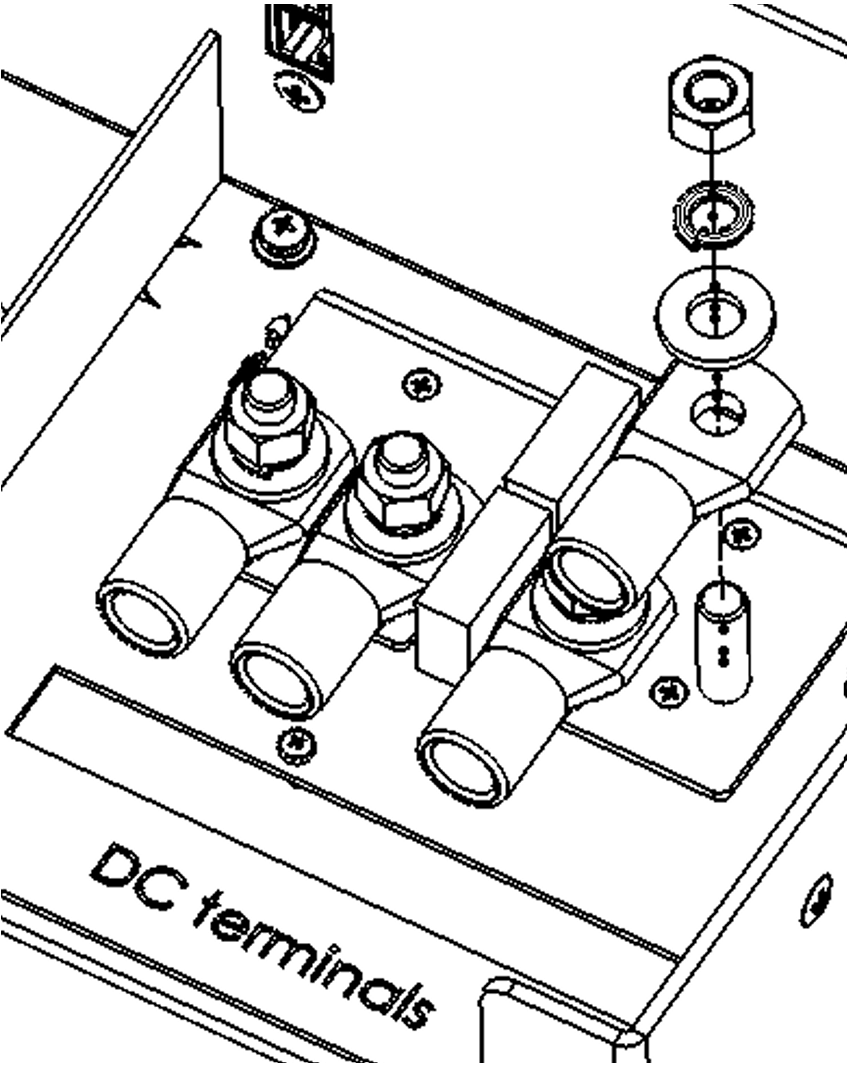
To connect the battery cables, follow the procedure below:
Warning
Use a torque wrench with an insulated box spanner in order to avoid shorting the battery.
Maximum torque: 14Nm
Avoid shorting the battery cables.
Connect battery cables as follows:
|
|
4.3. Connecting AC cables
Warning
The Quattro is a safety class I product (supplied with an ground terminal for safety purposes), only a TN-S grounding system is allowed). Its AC input and/or output terminals and/or grounding point on the outside of the product must be provided with an uninterruptable grounding point for safety purposes. See the following instructions in this regard.
The Quattro is provided with a ground relay (see block diagram appendix B) that automatically connects the N output to the casing if no external AC supply is available. If an external AC supply is provided, the ground relay will open before the input safety relay closes (relay H in appendix B). This ensures the correct operation of an earth leakage circuit breaker that is connected to the output.
In a fixed installation, an uninterruptable grounding can be secured by means of the grounding wire of the AC input. Otherwise the casing must be grounded.
In a mobile installation (for example, with a shore current plug), interrupting the shore connection will simultaneously disconnect the grounding connection. In that case, the casing must be connected to the chassis (of the vehicle) or to the hull or grounding plate (of the boat).
For all AC connections use M6 cable lugs.
In general, the connection described above to shore connection grounding is not recommended for boats because of galvanic corrosion. The solution to this is using an isolating transformer.
The inverter does incorporate a mains frequency isolating transformer. This precludes the possibility of DC current at any AC port. Therefore type A RCD’s can be used. The RCD must comply to IEC 61008-1 or IEC 61009-1 or to AS/NZS 61008.1 and AS/NZS 61009.1
Special notes regarding AS 4777.2 (Australia/New Zealand):
In installations where the continuity of the neutral to the load may not be interrupted, the installer must place a wire between AC-in N and AC-out N. Additionally, grid code “Australia X: AS/NZS 4777.2:2020 stand alone app. M (with N-bypass)” must be chosen. In this case the Earth relay (ground relay) remains open and in pass through mode the internal neutral relay will not be operated.
AC-in-1 (see appendix A, maximum torque: 7 Nm)
If AC voltage is present on these terminals, the Quattro will use this connection. Generally a generator will be connected to AC-in-1. An appropriate and readily accessible disconnect device shall be incorporated in the fixed wiring.
The AC-in-1 input must be protected by a fuse or magnetic circuit breaker rated at 100 A or less, and cable cross-section must be sized accordingly. If the input AC supply is rated at a lower value, the fuse or magnetic circuit breaker should be down sized accordingly.
AC-in-2 (see appendix A, maximum torque: 7 Nm)
If AC voltage is present on these terminals, the Quattro will use this connection, unless voltage is also present on AC-in-1. The Quattro will then automatically select AC-in-1. Generally the mains supply or shore voltage will be connected to AC-in-2.
The AC-in-2 input must be protected by a fuse or magnetic circuit breaker rated at 100 A or less, and cable cross-section must be sized accordingly. If the input AC supply is rated at a lower value, the fuse or magnetic circuit breaker should be down sized accordingly.
Note
The Quattro may not start when AC is present only on AC-in-2, and DC battery voltage is 10 % or more below nominal (less than 11 Volt in case of a 12 Volt battery).
Solution: connect AC power to AC-in-1, or recharge the battery.
AC-out-1 (see appendix A, maximum torque: 7 Nm)
The AC output cable can be connected directly to the terminal block “AC-out”.
With its PowerAssist feature the Quattro can add up to 5, 8, 10 or 15 kVA (forexample 10.000 / 230 = 43 A) to the output during periods of peak power requirement.
Together with a maximum input current of 100 A this means that the output can supply up to 100 + 21 = 121 A (5 kVA models), 100 + 35 = 135 A (8 kVA models), 100 + 43 = 143 A (10 kVA model) and 100 + 65 = 165 A (15 kVA model).
An earth leakage circuit breaker (30mA type A) and a fuse or circuit breaker rated to support the expected load must be included in series with the output, and cable cross-section must be sized accordingly. The maximum rating of the RCD is 30mA type A. The fuse or circuit breaker is 125 A (5 kVA models), 135 A (8 kVA), 143 A (10 kVA) resp. 165 A (15 kVA).
AC-out-2 (see appendix A, maximum torque: 7 Nm)
A second output is available that disconnects its load in the event of battery operation. On these terminals, equipment is connected that should operate only if AC voltage is available on AC-in-1 or AC-in-2, e.g. an electric boiler or an air conditioner. The load on AC-out-2 is disconnected immediately when the Quattro switches to battery operation. After AC power becomes available on AC-in-1 or AC-in-2, the load on AC-out-2 will be reconnected with a delay of approximately 2 minutes. This to allow a genset to stabilise.
AC-out-2 can support loads of up to 50 A. An earth leakage circuit breaker (30mA Type A) and fuse rated at max. 50 A must be connected in series with AC-out-2.
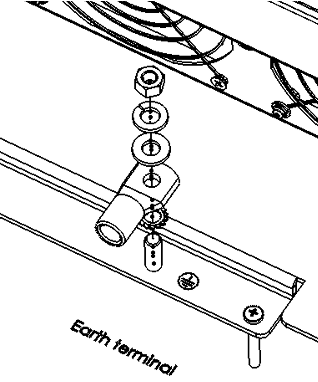
Earthing cable connection procedure Onsite wiring is required. M8 terminal. Use an appropriate ring lug to connect the earth cable to the terminal. Earth cable minimum cross sectional area: 16mm2 WarningEarth terminal maximum torque: 12Nm
|  |
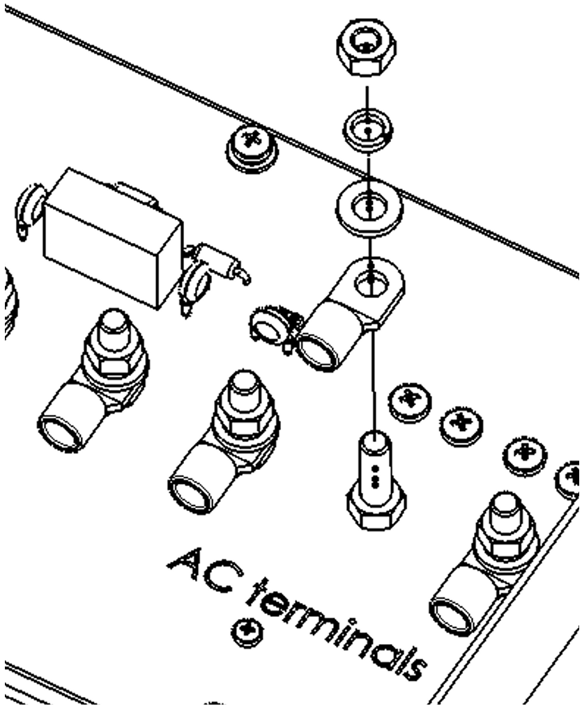
AC cable connection procedure Onsite wiring is required. M6 terminal. Use an appropriate ring lug to connect three core cable. WarningAC terminal maximum torque: 7Nm
|  |
4.4. Connection options
4.4.1. Starter battery
Connection terminal E, see appendix A
The Quattro has a connection for charging a starter battery. Output current is limited to 4 A.
(not available on 48 V models).
4.4.2. Voltage sense
Connection terminal E, see appendix A
For compensating possible cable losses during charging, two sense wires can be connected with which the voltage direct on the battery or on the positive and negative distribution points can be measured. Use at least wire with a cross-section of 0,75 mm2.
During battery charging, the Quattro will compensate the voltage drop over the DC cables to a maximum of 1 Volt (i.e. 1 V over the positive connection and 1 V over the negative connection). If the voltage drop threatens to become larger than 1 V, the charging current is limited in such a way that the voltage drop remains limited to 1 V.
4.4.3. Temperature sensor
Connection terminal E, see appendix A
For temperature-compensated charging, the temperature sensor can be connected. The sensor is isolated and must be fitted to the negative terminal of the battery.
Note
The temperature sensor is not supplied with 48V models.
It can be ordered separately. Order number: ASS000001000
4.4.4. Remote control
The Quattro can be remotely controlled in two ways:
With an external switch (connection terminal H, see appendix A). Operates only if the switch on the Quattro is set to “on”.
With a remote control panel (connected to one of the two RJ48 sockets B, see appendix A). Operates only if the switch on the Quattro is set to “on”.
Using the remote control panel, only the current limit for AC-in-2 can be set (in regard to PowerControl and PowerAssist).
The current limit for AC-in-1 can be set with DIP switches or by means of software.
Note
Only one remote control can be connected, i.e. either a switch or a remote control panel.
4.4.5. Programmable relays
Connection terminal I and E (K1 and K2), see appendix A
The Quattro is equipped with 3 programmable relays. The relay that controls terminal I is set as an alarm relay (default setting). The relays can be programmed for all kinds of other applications, for example to start a generator (VEConfigure software needed).
4.4.6. Auxiliary AC output (AC-out-2)
Besides the usual uninterruptable output (AC-out-1), a second output (AC-out-2) is available that disconnects its load in the event of battery operation. Example: an electric boiler or air conditioner that is allowed to operate only if the genset is running or shore power is available.
In case of battery operation, AC-out-2 is switched off immediately. After the AC supply has become available, AC-out-2 is reconnected with a delay of 2 minutes, this allow a genset to stabilise prior to connecting a heavy load.
4.4.7. Connecting Quattro units in parallel
See appendix C
The Quattro can be connected in parallel with several identical devices. To this end, a connection is established between the devices by means of standard RJ45 UTP cables. The system (one or more Quattro units plus optional control panel) will require subsequent configuration (see Section 5).
In the event of connecting Quattro units in parallel, the following requirements must be met:
A maximum of 6 units connected in parallel.
Only identical devices with the same power ratings may be connected in parallel.
Battery capacity should be sufficient.
The DC connection cables to the devices must be of equal length and cross-section.
If a positive and a negative DC distribution point is used, the cross-section of the connection between the batteries and the DC distribution point must at least equal the sum of the required cross-sections of the connections between the distribution point and the Quattro units.
Place the Quattro units close to each other, but allow at least 10 cm for ventilation purposes under, above and beside the units.
UTP cables must be connected directly from one unit to the other (and to the remote panel). Connection/splitter boxes are not permitted.
A battery-temperature sensor need only be connected to one unit in the system. If the temperature of several batteries is to be measured, you can also connect the sensors of other Quattro units in the system (with a maximum of one sensor per Quattro).
Temperature compensation during battery charging responds to the sensor indicating the highest temperature.
Voltage sensing must be connected to the master (see Section 5.5.1.4).
Only one remote control means (panel or switch) can be connected to the system.
4.4.8. Three-phase configuration
See appendix D
Quattro units can also be used in 3-phase wye (Y) configuration. To this end, a connection between the devices is made by means of standard RJ45 UTP cables (the same as for parallel operation). The system (Quattro units plus an optional control panel) will require subsequent configuration (see Section 5).
Pre-requisites: see Section 4.4.7.
Note
Tthe Quattro is not suitable for 3-phase delta (Δ) configuration.