1. Introduction
This document is primarily intended for Victron distributors. It is shared publicly for the benefit of professional installers and others who are comfortable with, and are able to, safely carry out the described tests themselves.
In case you are not, this is not a problem. It is not at all required to perform these tests yourself before sending a product to a dealer or distributor for checking or repair.
Before submitting a warranty claim, repair request or replacement request (RMA), Victron Energy requires that the unit in question is bench tested by our direct customer (the Victron Energy distributor). This is to prevent an RMA from being submitted for non-faulty units or units with non-warrantable faults.
This document describes the setup and equipment needed to perform a successful bench test and contains testing instructions for most Victron Energy product groups, which need to be completed before an RMA is submitted.
The tests described in this document cover all basic functionality. Some lesser-used or simpler-to-test product features are not included. For example, programmable relays, communication ports, remote on/off terminals and so forth. Should these be reported by your customer as faulty, then, of course, bench test for that.
1.1. Safety
The cover of our products may only be removed by a qualified technician with electronic or electromechanical training who is aware of the local safety guidelines and requirements.
Warning
Before testing a Victron Energy product, always refer to the safety instructions listed in its product manual. Product manuals are available from the product pages on the Victron Energy website.
Some basic safety guidelines:
AC voltage is dangerous and harmful. Use fused circuit breakers and RCDs.
DC voltage is dangerous and harmful.
Do not short circuit batteries.
When working with batteries, make sure all DC loads are sufficiently fused.
Be aware that lead-acid battery charging can create explosive gasses.
Always use electrically insulated tools.
1.2. Testing equipment, test bench and tools
To be able to confirm if a Victron Energy product is faulty, it needs to be individually tested. These tests are performed on a dedicated test bench. The test bench contains all equipment needed for the test.
Ideally, this test bench is permanently set up in your workshop and readily accessible.
The test bench is one of your own design. It contains all relevant equipment that is needed for testing a Victron Energy product.
A test bench generally contains the following items:
Battery bank and DC power supply.
DC loads and AC loads.
DC and AC circuit breakers and automatic fuses.
DC and AC electrical cables with a variety of core thicknesses.
Tools.
Electrical measuring equipment.
Computer and a tablet or smartphone.
Interfaces and data cables.
A peak current limiting resistor is needed to test the SUN Inverter's PV input. Two resistors of 1 Ohm, 200 Watt, are used in parallel for the 12/250 Sun inverter and in series for the 24/250 Sun inverter. Ensure that these resistors are rated in "free air" or alternatively mount them on an appropriate heatsink.
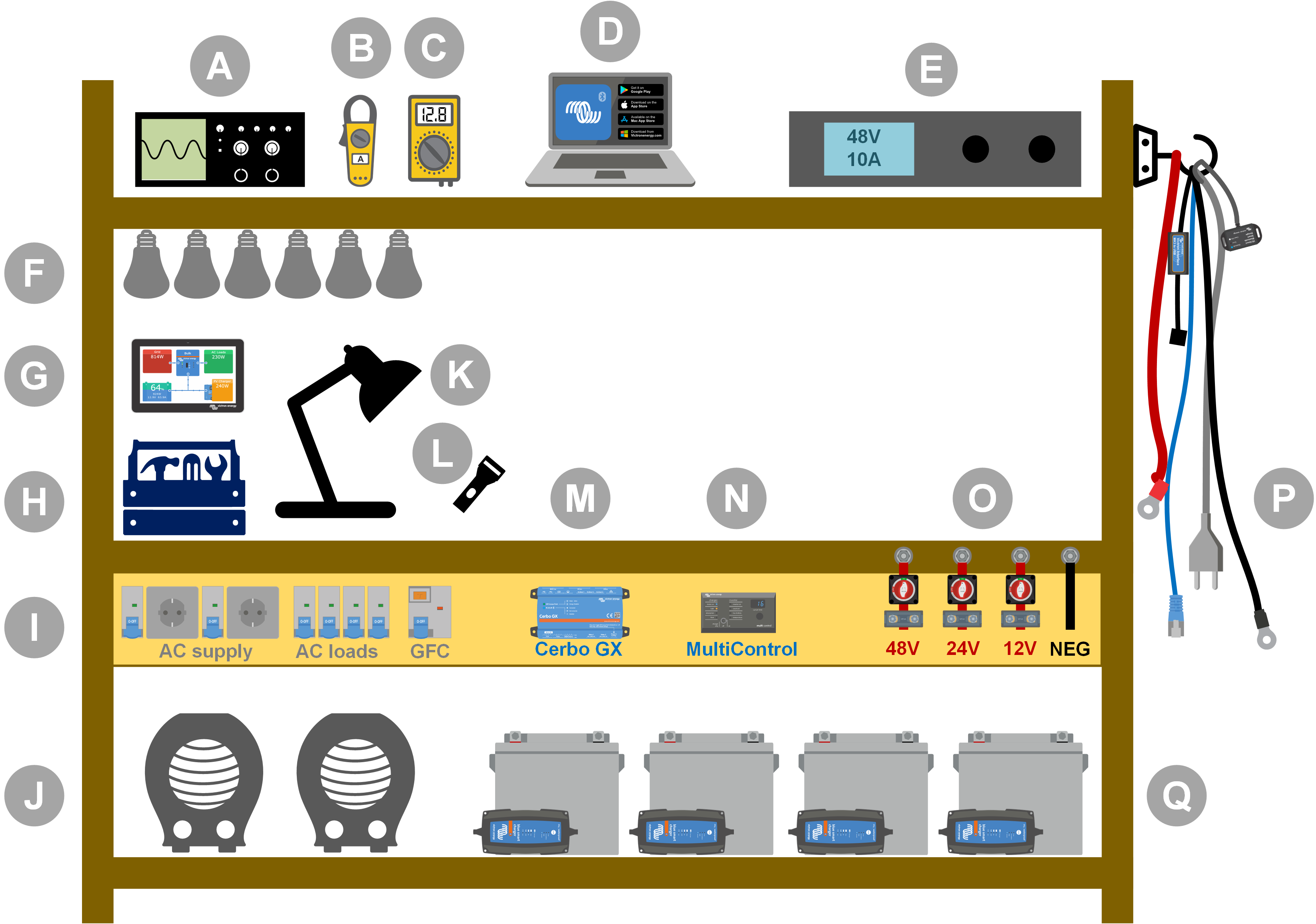
Example of a test bench.
ID | Description |
|---|---|
A | Oscilloscope (optional) |
B | Current clamp |
C | Multimeter |
D | Computer and a tablet or smartphone |
E | Power supply |
F | AC and/or DC incandescent light globes |
G | Touch GX |
H | Tools |
I | AC distribution board |
J | AC heaters |
K | Lamp |
L | Torch |
M | Cerbo GX |
N | Digital Multi control panel |
O | DC distribution board |
P | Cables and interfaces |
Q | Battery bank |
1.2.1. Tools
Always use insulated tools:
Working with electricity and batteries is dangerous. Avoid shorting battery terminals or the DC terminals inside our products. Use insulated nut drivers or spanners to prevent accidental short circuits.
 |
Wiha insulated tool set with screwdrivers, nut drivers, pliers, cutters and so on.
Use appropriately sized tools and tighten correctly:
Almost all nuts, screws and bolts used in Victron Energy units are metric. Please use the appropriately sized tools.
Most connection bolts and screws are made of brass, as such, avoid over-tightening. A brass bolt or screw can easily snap. Use a torque spanner to prevent this. The appropriate torque settings are listed in the product manual.
If the torque moment is unknown, use this as a guide:
M4 bolts, screws and nuts = 1Nm.
M5 bolts, screws and nuts = 3Nm.
M6 bolts, screws and nuts = 5.5Nm.
M8 bolts, screws and nuts = 12Nm.
Avoid over-tightening cabinet screws. You can use automatic screwdrivers but check that you use a middle torque setting.
Crimping tools:
Ensure that the electrical cables have terminals suitable for the electrical connections that need to be made.
Use the correct crimping tool when crimping cable terminals onto cables.
1.2.2. DC source
A DC power supply or a set of batteries able to supply 12V, 24V or 48V.
DC Power supply:
Use a regulated DC power supply that is adjustable between 0-60V and 0-40A, like the DeltaElektronika SM3300 series. A power supply is the preferred option because it is capable of current limiting, thus eliminating the need for DC fusing.
Batteries:
If a power supply is not available, use batteries instead. Use four 12V batteries to create a 12V, 24V or 48V battery bank. But be aware that a battery short circuit should be prevented at all times, so DC fuses need to be used as well. For ease of use, use automatic fuses.
Multiple voltage battery bank:
Please refer to the image below for an example of a battery bank capable of supplying multiple voltages. To maintain balanced and charged batteries, connect a BlueSmartIP65 charger to each individual battery.
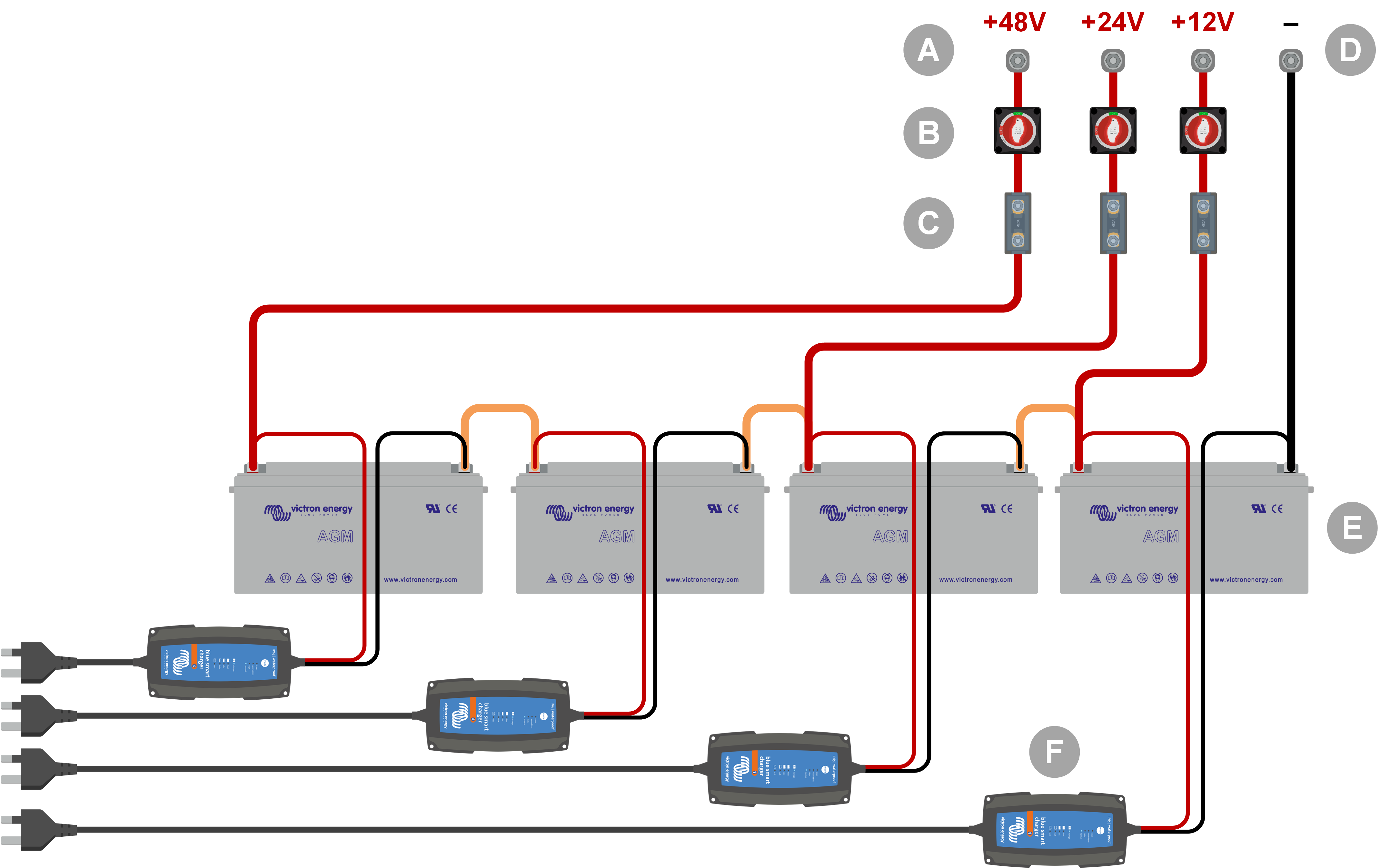
Example of a multiple voltage battery bank.
ID | Description |
|---|---|
A | 12V, 24V and 48V battery connections |
B | Battery isolator switches |
C | Fuses and fuse holders or automatic fuses |
D | Negative battery connection |
E | Batteries |
F | BlueSmart IP65 battery chargers |
1.2.3. DC loads
Some examples of DC loads:
A DC load bank.
An inverter is running an AC load.
DC incandescent light globes.
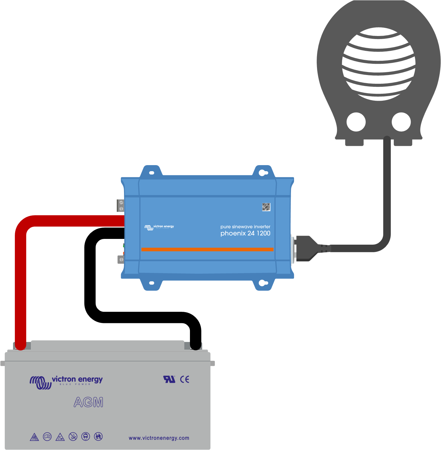 |
An Inverter used as a DC load
1.2.4. AC source
Use the grid (mains) as an AC source. Do not use a generator, as they often have an inferior sine wave.
To obtain another AC voltage, you can use a variable transformer (Variac) or a Victron isolation transformer to convert the grid voltage to the required voltage. This allows you to test 110Vac equipment in a 230Vac country or vice versa.
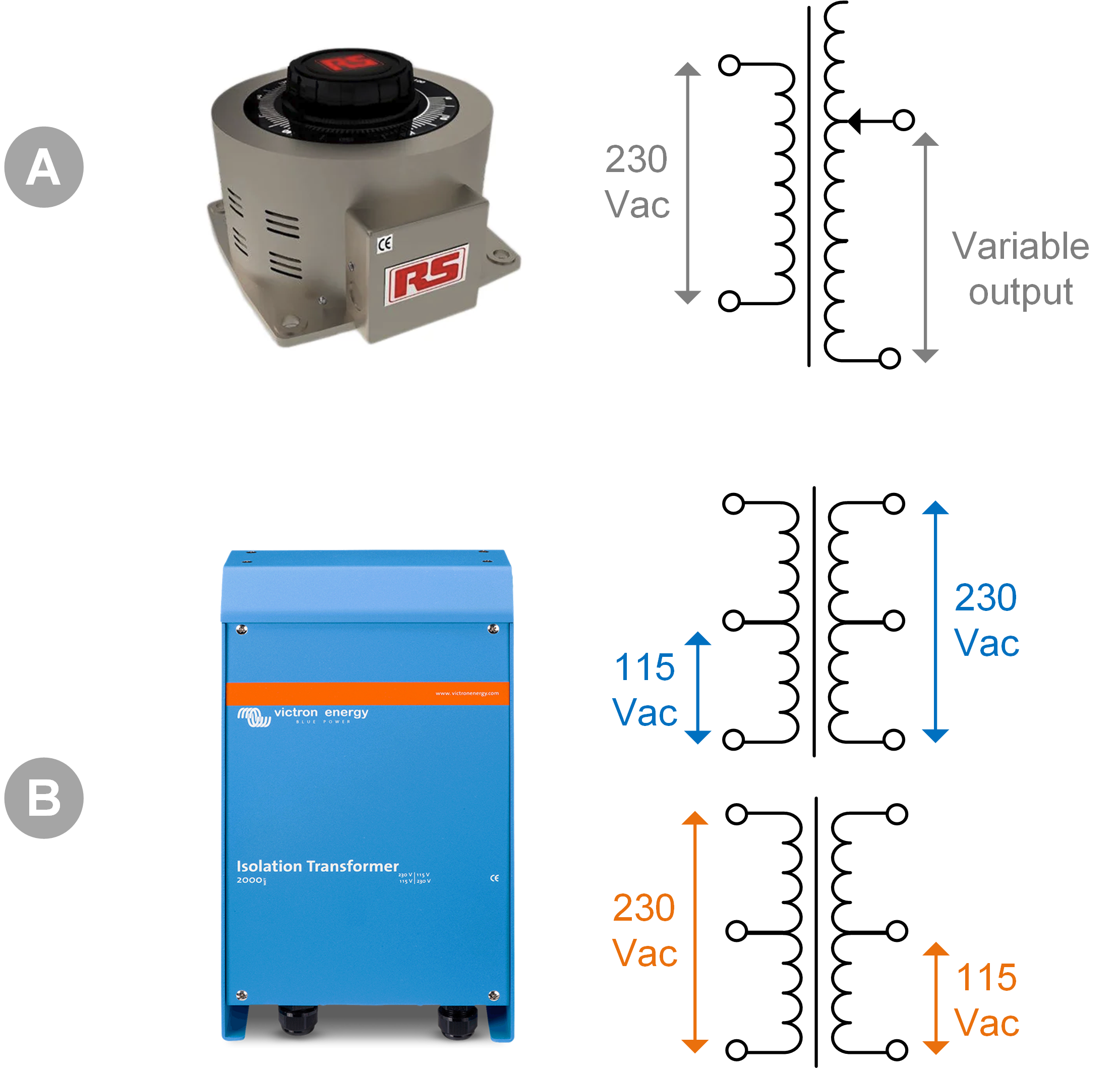 |
A) Variac
B) Isolation transformer
1.2.5. AC loads
Some examples of AC loads:
Electric heaters.
Incandescent AC lamps.
Note: Do not use heat guns (paint strippers). These are not suitable for load testing because they are non-linear loads, they do not load the whole sine wave equally.
1.2.6. Cables and interfaces
DC and AC cabling need to have the thicknesses recommended in the product manual of the tested unit.
Note that the DC cables and connectors between the DC supply and the to-be-tested device must be able to deal with the large DC currents that are common in low voltage systems. If too thin cables are used, this will lead to potential voltage drops and will interfere with the test results.
Interface MK3-USB: Use this to communicate with a computer via VE.Bus using the VictronConnect app or the VEConfigure software. See A in below image.
VE.Direct to USB interface: Use this to communicate with a computer to the VE.Direct port. This is handy when the Windows version of the VictronConnect app is used. See B in below image.
VE.Direct Bluetooth Smart dongle: Use this to communicate with Bluetooth via the VE.Direct port to bypass its built-in Bluetooth interface. This is handy in case the PIN of the product is unknown. See C in below image.
VE.Direct cable: Use this to connect a GX device to a VE.Direct port.
RJ45 UTP cable: Use this to connect an interface or a GX device to a VE.Bus or VE.Can port.
VE.Can RJ45 terminator: Use this for VE.Can communication.
RJ12 UTP cable: Use this between the BMV head unit and the BMV shunt. This is handy in case the BMV RJ12 UTP cable is missing or to rule out a cable issue.
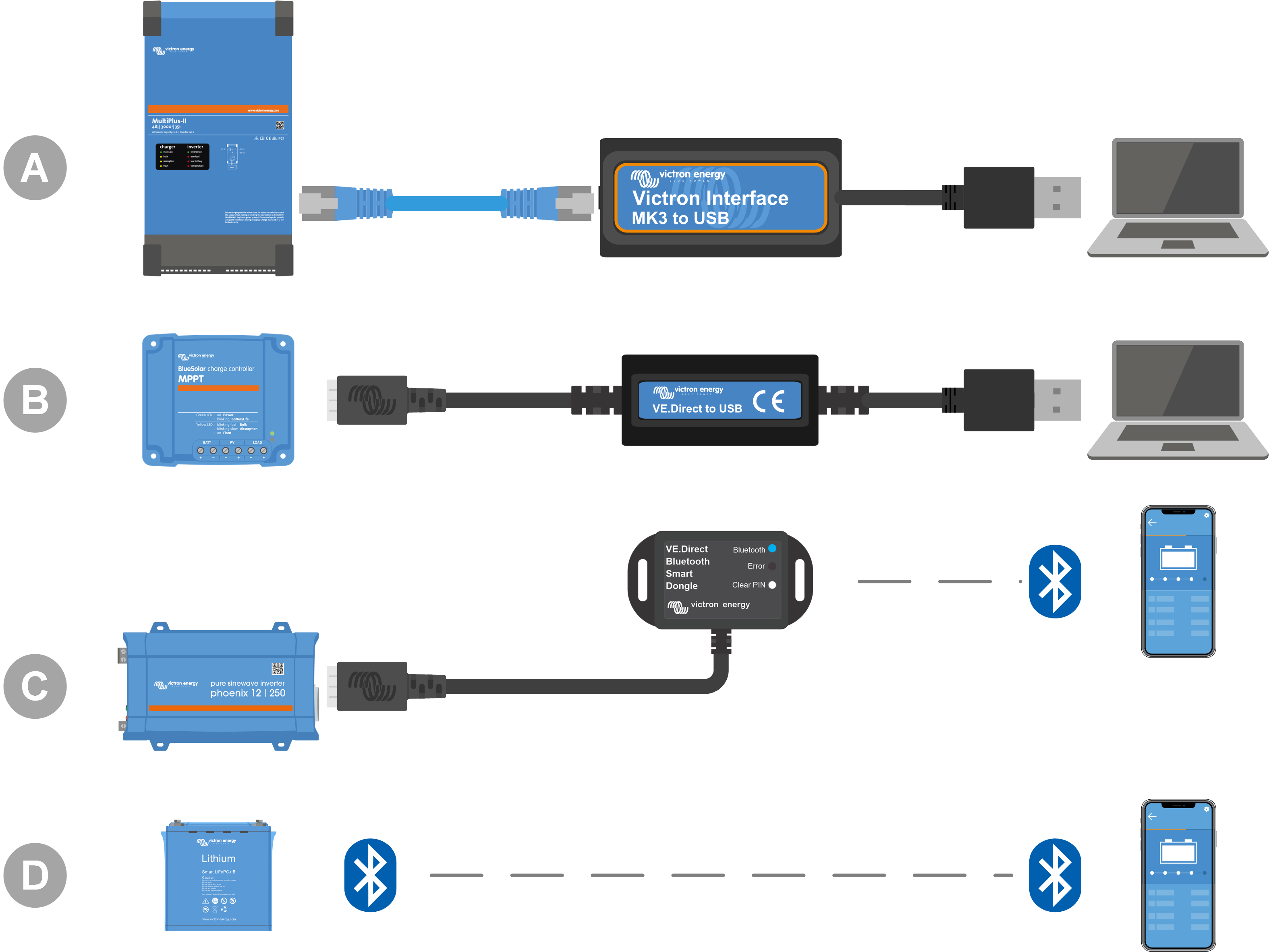 |
Example of connecting for configuration access.
ID | Description |
|---|---|
A | An Interface MK3-USB is used to connect VE.Bus units to a computer's USB port for access with the VictronConnect app or VEConfigure software. |
B | A VE.Direct to USB interface is used to connect VE.Direct units to a computer's USB port for access with the VictronConnect app or VEConfigure software. |
C | A VE.Direct Bluetooth Smart dongle is used to connect VE.Direct units via Bluetooth to a phone or tablet for access with the VictronConnect app. |
D | A direct Bluetooth connection to a phone or tablet for access with the VictronConnect app |
1.2.7. Measurement equipment and software
The following measuring equipment and software are needed:
A true RMS multimeter, such as a Fluke 87 multimeter.
A DC current clamp. For example, the Fluke i1010 AC/DC Current Clamp i1010 AC/DC can be used together with the Fluke 87 multimeter.
The VictronConnect app to monitor, configure or update the firmware.
The VE.Configuration tools software package to configure or update VE.Bus products. However, it is essential to note that, in most cases, the VictronConnect app should be preferred for these tasks. The only exceptions are when setting or resetting grid codes, changing or removing assistants, or encountering issues with a firmware update.
A Cerbo GX with a GX Touch screen and a VRM account. The Cerbo GX serves multiple purposes, including monitoring units, reading out errors, configuring settings, updating firmware, and providing remote access.
A simple design oscilloscope (optional). If you decide to use an oscilloscope, ensure that you have a probe suitable for measuring 110Vac and 230Vac."