4. Installazione
4.1. Ubicazione dell’Multi RS Solar
 | Per assicurare un funzionamento senza problemi, l’Multi RS Solar deve essere utilizzato in luoghi che riuniscano i seguenti requisiti: a) Evitare qualsiasi contatto con l’acqua. Non esporre il prodotto a pioggia e umidità. b) Installare l’Multi RS Solar in posizione verticale. Predisporre uno spazio di 30 cm sopra e sotto di esso. c) L’Multi RS Solar deve essere installato su una superficie non infiammabile e anche i materiali di costruzione che circondano l'impianto devono essere non infiammabili. b) Non consentire che l’unità riceva luce solare diretta. La temperatura ambiente dell’aria deve essere compresa fra -40 ºC e 60 ºC (umidità < 95 % senza condensa). e) Non installare l’Multi RS Solar in un ambiente in cui l'aria potrebbe essere contaminata da materiale particolato come fuliggine, polvere o sale. Ad esempio, la fuliggine conduttiva proveniente dallo scarico di un generatore diesel potrebbe essere aspirata dall'unità e causare cortocircuiti al suo interno. f) Non installare l’Multi RS Solar in luoghi in cui gas o vapori infiammabili o corrosivi potrebbero avvicinarsi all'impianto. g) Non ostruire la circolazione dell’aria attorno all’Multi RS Solar. h) Se l’Multi RS Solar è installato in un'area adibita a magazzino generale, assicurarsi che nelle vicinanze dell'impianto non siano conservati materiali infiammabili come scatole di cartone. Assicurarsi che l'utente finale sia a conoscenza di questi requisiti. | |
| Questo prodotto contiene tensioni potenzialmente pericolose. Deve essere installato solamente sotto la supervisione di un installatore qualificato e che abbia ricevuto l’opportuna formazione, in base alle leggi locali. Si prega di contattare Victron Energy per ulteriori informazioni o per l’opportuna formazione | |
| Una temperatura ambiente troppo elevata porta alle seguenti conseguenze: · Durata di vita ridotta. · Corrente di carica ridotta. · Potenza di picco ridotta o arresto dell’inverter. Non posizionare mai il dispositivo direttamente sopra batterie al piombo acido. L’unità è predisposta per il montaggio a muro. Ai fini del montaggio, nella parte posteriore della carcassa si trovano due fori ed un gancio. Il dispositivo deve essere montato in verticale, per consentire un raffreddamento ottimale. | |
| Ai fini della sicurezza, installare il presente prodotto in un ambiente termo-resistente. Accertarsi che nelle immediate vicinanze non vi siano sostanze chimiche, elementi in materiale sintetico, tende e altri materiali tessili, ecc. | |
| Non collegare mai le batterie direttamente al Multi RS Solar senza aver predisposto un'adeguata protezione del circuito. Assicurarsi sempre che tra le batterie e il Multi sia installata un'adeguata protezione del circuito. | |
| Le batterie devono avere una classe di infiammabilità HB o superiore. | |
| Ogni sistema necessita una modalità di disconnessione dei circuiti CA e CC. Se il dispositivo di protezione da sovracorrente è un interruttore, può fungere anche da dispositivo di disconnessione. Se si utilizzano dei fusibili, è necessario installare dei fusibili di disconnessione a parte tra la sorgente e i fusibili stessi. |
Ridurre al minimo la distanza tra il prodotto e la batteria, in modo da ridurre al massimo la perdita di tensione dei cavi.
4.2. Requisiti delle batterie e del cavo batteria
Per sfruttare a pieno il potenziale del prodotto, utilizzare batterie con capacità sufficiente e cavi di collegamento della batteria con una sezione adeguata. L’utilizzo di batterie o cavi batteria sottodimensionati può causare:
Riduzione dell’efficienza del sistema,
Allarmi o arresti del sistema non desiderati,
Danni permanenti al sistema
Vedere la tabella per sapere i requisiti MINIMI della batteria e dei cavi.
Capacità della batteria | Piombo-acido: | 200 Ah |
Litio | 50 Ah | |
Fusibile CC consigliato | Cavo da 35 mm2 | 125 A |
Cavo da 70 mm2 | 200 A | |
Sezione trasversale minima (mm2) dei morsetti di collegamento + e - | 0 - 2 m | 35 mm2 |
2 - 5 m | 70 mm2 |
Avvertimento
Consultare le raccomandazioni del produttore della batteria per assicurarsi che le batterie possano sopportare la corrente di carica totale del sistema. Per decidere le dimensioni della batteria, rivolgersi al progettista del sistema.
 | Utilizzare una chiave di serraggio con isolamento per evitare di mettere in cortocircuito la batteria. Coppia massima: 14 Nm Evitare di mettere in cortocircuito i cavi di collegamento della batteria. |
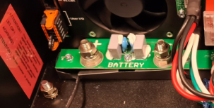
Per accedere ai morsetti della batteria, allentare le due viti sul fondo della carcassa e rimuovere il coperchio per esporre il vano di servizio.
|
|
|
|
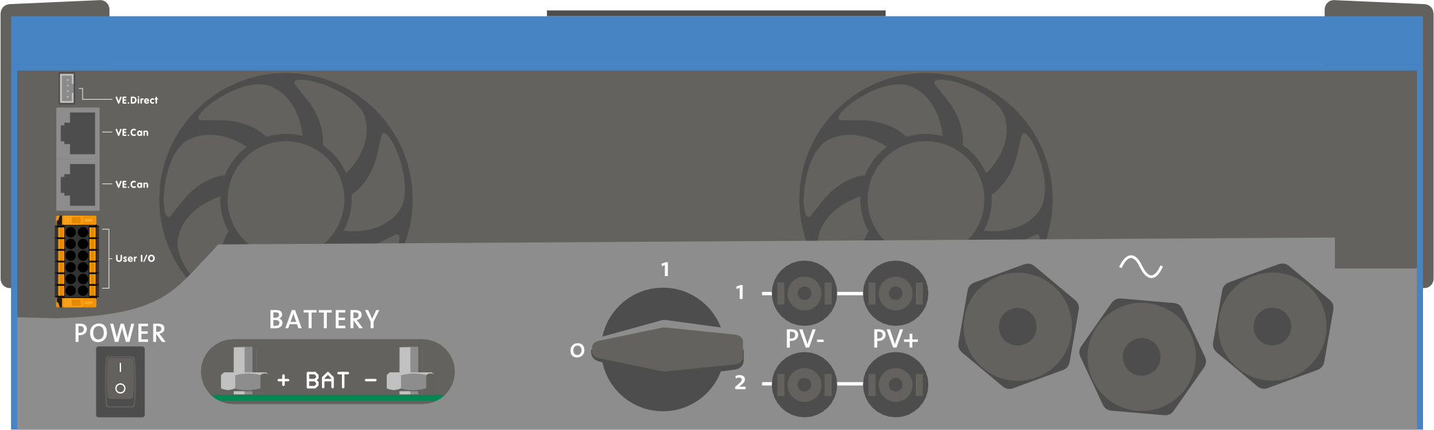
4.3. Configurazione del modulo fotovoltaico
Il modello Multi RS Solar a doppio rilevatore deve mantenere isolati tra loro gli ingressi dei singoli rilevatori. Ciò significa un solo modulo FV per ogni entrata: non tentare di collegare lo stesso modulo a varie entrate dei tracciatori.
Avvertimento
Per i collegamenti del FV al Multi RS Solarutilizzare sempre connettori MC4 originali Staubli.
I connettori di altre marche potrebbero non essere completamente compatibili con i connettori Staubli del Multi RS Solar.
Il Multi RS Solar è costruito con connettori Staubli MC4. Esistono molte altre marche disponibili, ma alcune variazioni di produzione fanno sì che il contatto possa risultare scadente e causare un calore eccessivo. Sul mercato sono presenti anche marche di qualità inferiore che probabilmente causeranno problemi.
Avvertimento
La tensione nominale massima del caricabatterie solare è di 450 V. Un evento di sovratensione FV danneggia il caricabatterie solare. Questo danno non è coperto dalla garanzia.
Se situato in climi più freddi, il modulo FV può produrre più della sua Voc nominale. Per calcolare questa variabile, utilizzare il calcolatore delle dimensioni dell’MPPT, che si trova nella pagina prodotto del caricabatterie solare. Come regola empirica, mantenere un ulteriore margine di sicurezza del 10 %.
La massima corrente operativa in ingresso di ogni tracciatore è di 12 A.
Le entrate FV del MPPT sono protette contro polarità inversa, fino a una corrente massima di cortocircuito di 16 A per ogni tracciatore.
Avvertimento
Sebbene sia pratico con una corretta installazione, FARE ATTENZIONE, giacché la garanzia del prodotto si annulla se un modulo FV con una corrente di cortocircuito superiore a 16 A è collegato con polarità inversa.
Attenzione
Il modello Multi RS Solar a doppio rilevatore deve mantenere isolati tra loro gli ingressi dei singoli rilevatori. Ciò significa un solo modulo FV per ogni entrata: non tentare di collegare lo stesso modulo a varie entrate dei tracciatori.
Quando un MPPT passa alla fase di mantenimento, riduce la corrente di carica della batteria, incrementando la tensione del Punto di Potenza del FV.
La tensione massima a circuito aperto del modulo FV deve essere inferiore a 8 volte la tensione minima della batteria, quando si trova in mantenimento.
Ad esempio, se una batteria possiede una tensione di mantenimento di 54,0 Volt, la tensione massima a circuito aperto del modulo collegato non deve superare i 432 Volt.
Se la tensione del modulo supera questo parametro, il sistema mostra un errore di “Protezione contro Sovraccarica” e si arresta.
Per correggere questo errore, aumentare la tensione di mantenimento della batteria oppure ridurre la tensione del FV, togliendo dei pannelli FV dalla stringa, al fine di riportare la tensione entro i valori indicati.
4.3.1. Esempio di configurazione FV del Multi RS Solar
Avviso
Questo è un esempio di configurazione di un modulo. Per decidere la configurazione specifica del modulo, il dimensionamento e la progettazione del sistema, consultare il progettista del sistema stesso.
Tipo Pannello | VoC | Vmpp | Isc | Impp | # di pannelli | Max Tensione Stringa | Potenza totale |
|---|---|---|---|---|---|---|---|
Victron 260 W (60 celle) | 36.75 V | 30 V | 9,30 A | 8,66 A | #1 - 8 #2 - 8 | 304 V | 4160 W |
4.4. Messa a terra del MPPT, rilevamento di difetti di isolamento del modulo FV e notifica allarme di guasto a terra
Il Multi RS Solar verifica la presenza di un isolamento resistivo sufficiente tra FV+ e GND e tra FV- e GND.
In caso di resistenza inferiore alla soglia (che indica un guasto a terra), l'inverter si spegne e disattiva le uscite CA (l’MPPT continua a caricare la batteria, in quanto ciò non ha alcun impatto sulla sicurezza, grazie all'isolamento sul lato batteria).
Se si desidera ricevere una notifica di tale guasto mediante allarme sonoro e/o tramite e-mail, è necessario collegare anche un dispositivo GX (come il Cerbo GX). Le notifiche tramite e-mail richiedono una connessione Internet al dispositivo GX e la configurazione di un account VRM.
I conduttori positivi e negativi del modulo FV devono essere isolati dalla terra.
Mettere a terra la struttura del modulo FV in base ai regolamenti locali. La linguetta di terra del telaio deve essere collegata a terra.
Il conduttore che va dalla linguetta di terra, sita sul telaio dell’unità, alla terra deve possedere almeno la sezione dei conduttori utilizzati per il modulo FV.
Quando viene indicato un difetto di resistenza di isolamento del FV, non toccare alcuna parte metallica e rivolgersi immediatamente a un tecnico qualificato, che possa ispezionare il sistema per trovare il problema.
I morsetti della batteria sono isolati galvanicamente dal modulo FV. Ciò assicura che le tensioni del modulo FV non passino al lato batteria del sistema in caso di guasto.
4.5. Sequenza di collegamento dei cavi
Primo: Confermare la corretta polarità della batteria, collegare la batteria.
Secondo: se necessario, collegare accensione - spegnimento remoto e relè programmabile, nonché i cavi di comunicazione
Terzo: Confermare la corretta polarità del FV, quindi connettere il modulo fotovoltaico (se lo si collega con polarità inversa, la tensione FV cade e il regolatore si surriscalda ma non carica la batteria).
4.6. Procedura di collegamento della batteria
Per collegare i cavi della batteria, procedere come segue:
Avvertimento
Utilizzare una chiave di serraggio dinamometrica con chiave a bussola isolata per evitare di cortocircuitare la batteria. Evitare di mettere in cortocircuito i cavi della batteria.
Avvertimento
Al momento di effettuare le connessioni elettriche, bisogna prestare particolari cure e attenzioni. La corretta polarità deve essere confermata mediante un multimetro prima della connessione. Collegare una batteria con una polarità erronea provoca la distruzione del dispositivo e non è coperta dalla garanzia.
Allentare le due viti sul fondo della custodia e rimuovere il pannello di servizio.
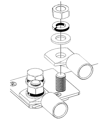
Collegare i cavi della batteria: Prima il cavo - e poi il cavo +. Prestare attenzione, giacché potrebbero saltare alcune scintille durante il collegamento della batteria.
Serrare i dadi in base alla coppia indicata per determinare una resistenza di contatto minima.
4.7. Connessione del cablaggio CA
Avvertimento
Assicurarsi sempre che il Multi RS Solar sia spento e che l'ingresso CA sia isolato prima di rimuovere il coperchio del vano cavi.
Avvertimento
Questo è un prodotto in classe di sicurezza I (fornito con morsetto di terra ai fini della sicurezza). I morsetti di entrata e/o uscita CA e/o il punto di messa a terra all’interno del prodotto devono essere dotati di un punto di messa a terra continuo di sicurezza.
Negli impianti fissi è possibile assicurare la messa a terra continua tramite il cavo di terra dell’ingresso CA. Altrimenti bisogna mettere a terra la carcassa.
Questo prodotto è dotato di un relè di terra che collega automaticamente l'uscita Neutro al telaio se non è disponibile un'alimentazione CA esterna. Se è presente un'alimentazione CA esterna, il relè di terra H si apre prima che si chiuda il relè di sicurezza di ingresso. Ciò garantisce il corretto funzionamento di un interruttore differenziale di dispersione a terra collegato all'uscita.
In impianti mobili (ad esempio, con una presa di corrente di banchina), l’interruzione del collegamento di banchina causa la contestuale interruzione del collegamento a terra. In tal caso si dovrà collegare la carcassa al telaio del veicolo.
È necessario installare in serie con l’uscita un fusibile o un interruttore automatico in grado di sopportare il carico previsto e la sezione del cavo va dimensionata di conseguenza.
Nota
Il Multi RS Solar non fornisce un isolamento galvanico completo tra l'ingresso CC del FV e i terminali CA.
In conformità alle norme IEC62109-1 e IEC62109-2, un'unità interna di monitoraggio della corrente residua (RCMU) garantisce che non ci sia mai CC sul lato CA. Vengono monitorati i tipi di componenti della corrente di guasto sia CC che CA. Se viene rilevato un guasto, l'inverter si spegne automaticamente, scollegando il sistema CA.
Assicurarsi che l'installazione di CA sia conforme alle normative locali in materia di protezione dalle correnti residue. Per ulteriori informazioni, consultare il documento Informazioni RCD sul Multi RS.
Nota
Tra la CA e la CC della batteria è garantito un isolamento galvanico totale.
Le morsettiere di collegamento CA si trovano sul lato destro del vano cavi.
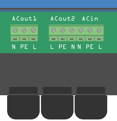
Tali morsettiere CA sono del tipo con morsetto a vite.
Avvertimento
È necessario scorticare l’isolamento per esporre 10 mm di conduttore nudo.
La coppia di serraggio massima è di 1,2 Nm.
Avvertimento
NON invertire la polarità dei conduttori di neutro e linea quando si collega il cablaggio CA.
AC-out-1 Il cavo di uscita CA può essere collegato direttamente alla morsettiera "AC-out". Da sinistra a destra: "N" (neutro) - "PE" (terra) - "L" (fase). Grazie alla funzione PowerAssist, il Multi può aggiungere fino a 6 kVA (cioè 6000 / 230 = 26 A) all'uscita durante i periodi di richiesta di picco della potenza. Il Multi RS può fornire ai carichi una portata fino a 50 A. I relè di ingresso CA sono limitati a 50 A (Multi RS - 2 tracciatori) e l'inverter può apportare fino a 25 A continui nelle migliori condizioni (quando fa più caldo questo valore si riduce).
Avvertimento
I terminali di uscita CA devono essere protetti da sovraccarico mediante un fusibile o un interruttore con portata di 50 A o inferiore e la sezione del cavo deve essere dimensionata di conseguenza.
AC-out-2 È disponibile una seconda uscita in grado di scollegare il proprio carico in caso di funzionamento della sola batteria. A questi morsetti sono collegati apparecchi che possono funzionare solamente se è disponibile tensione CA in AC-in-1, ad es., una caldaia elettrica o un condizionatore d’aria. Il carico su AC-out-2 viene scollegato immediatamente quando l’inverter/caricabatterie passa al funzionamento con batteria. Nel momento in cui diventa disponibile l'alimentazione CA su AC-in-1, viene immediatamente ricollegato anche il carico su AC-out-2.
AC-in Il cavo dell’ingresso CA può essere collegato alla morsettiera “AC-in”. Da sinistra a destra: “N” (neutro) - “PE” (terra) - “L” (fase). L’ingresso CA deve essere protetto da sovraccarico mediante un fusibile o un interruttore con portata di 50 A o inferiore e la sezione del cavo deve essere dimensionata di conseguenza. Se l’alimentazione CA dell’ingresso ha portata inferiore, il fusibile o l’interruttore deve essere dimensionato in base a tale portata.
4.8. VE.Direct
Si può utilizzare per collegare un PC/portatile, al fine di configurare l’inverter mediante un accessorio VE.Direct a USB. Si può usare anche per collegare un GlobalLink 520 di Victron, consentendo il monitoraggio remoto dei dati.
Nota
La porta VE.Direct del Multi RS Solar non può essere utilizzata per collegarsi a un dispositivo GX, pertanto è necessario utilizzare la connessione VE.Can.
4.9. VE.Can
Le porte VE.Can possono servire per collegarsi ad altri dispositivi, ad esempio:
Un dispositivo GX per il monitoraggio e la comunicazione.
Altri dispositivi Multi RS Solar che formano un sistema trifase.
Un contatore di energia come il Victron VM-3P75CT.
MPPT aggiuntivi come l'MPPT RS o altri regolatori MPPT VE.Can.
Importante
È sempre necessario installare dei terminatori VE.Can nei dispositivi che si trovano alle due estremità della rete VE.Can.
4.10. Bluetooth
Utilizzato per il collegamento al dispositivo tramite VictronConnect per la configurazione.
Tenere presente che quest’interfaccia Bluetooth non è compatibile con il collegamento in rete VE.Smart (ad es., Smart Battery Sense).
4.11. Utente I/O
La morsettiera I/O utente si trova sul lato sinistro all'interno del vano di cablaggio.
La morsettiera può essere rimossa per agevolare il collegamento di piccoli cavi. Per sbloccarla, spingere entrambe le leve arancioni (in alto e in basso sul connettore) verso sinistra.
I collegamenti si effettuano spingendo il cavo nel foro. Nell'orientamento "TOP", si può rilasciare il cavo spingendo verso il basso la linguetta arancione accanto al foro con un piccolo cacciavite a lama piatta.
Nota
Nella posizione Remote_H e Remote_L viene installato in fabbrica un collegamento cablato. In questo modo, si attiva il funzionamento predefinito del Multi RS Solar. Se viene rimosso questo collegamento cablato o il connettore, i terminali Remote_H e Remote_L diventano un circuito aperto e il Multi RS Solar non si accende.
Il seguente diagramma mostra il pinout del connettore e la funzione di ogni pin. Le funzioni sono stampate anche sul lato del connettore stesso.

Numero di pin | Nome del pin | Descrizione |
|---|---|---|
1 | Relay_NO | Connessione relè programmabile Normalmente Aperto |
2 | AUX_IN- | Negativo comune per entrate ausiliarie programmabili |
3 | AUX_IN1+ | Connessione positivo ingresso ausiliare programmabile 1 |
4 | AUX_IN2+ | Connessione positivo ingresso ausiliare programmabile 2 |
5 | REMOTE_L | Connettore on/off remoto Basso |
6 | REMOTE_H | Connettore on/off remoto Alto |
7 | RELAY_NC | Connessione relè programmabile Normalmente Chiuso |
8 | RELAY_COM | Relè programmabile Comune |
9 | TSENSE- | Negativo sensore di temperatura |
10 | TSENSE+ | Positivo sensore di temperatura |
11 | VSENSE- | Negativo sensore tensione |
12 | VSENSE+ | Positivo sensore tensione |
4.11.1. Terminali remoti H e L
Sono presenti due terminali contrassegnati da REMOTE_H e REMOTE_L.
La funzione predefinita di questi terminali è l'accensione o lo spegnimento da remoto del Multi RS Solar.
Nota
Questi due terminali vengono collegati tra loro in fabbrica mediante un cavo di collegamento. Ciò consente al Multi RS Solar di accendersi quando il suo interruttore fisico principale è acceso.
Per utilizzare i terminali delle connessioni remote è necessario rimuovere il collegamento cablato.
Questi due contatti possono essere configurati per l'on/off remoto (impostazione predefinita) o per la modalità BMS a 2 cavi.
Se un sistema è formato da due unità combinate, ad esempio, in una configurazione trifase, i cavi di contatto possono essere collegati a qualsiasi unità singola. Lo stato del contatto viene quindi condiviso con il resto del sistema attraverso le connessioni VE.Can.
È necessario configurare solo l'unità a cui sono collegati i cavi di contatto.
Funzionalità di on/off remoto:
È possibile rimuovere il collegamento cablato montato in fabbrica e i cavi possono essere collegati a un contatto di commutazione esterno. Il contatto dell'interruttore può quindi essere utilizzato per accendere o spegnere il Multi RS Solar.
Questa è la configurazione predefinita di VictronConnect; non è necessario apportare modifiche alla configurazione di una nuova unità. La configurazione può essere controllata in Modalità remota nel menu Impostazioni batteria.
Il Multi RS Solar verrà acceso se gli ingressi sono cablati in una delle quattro modalità raffigurate sulla destra.
| 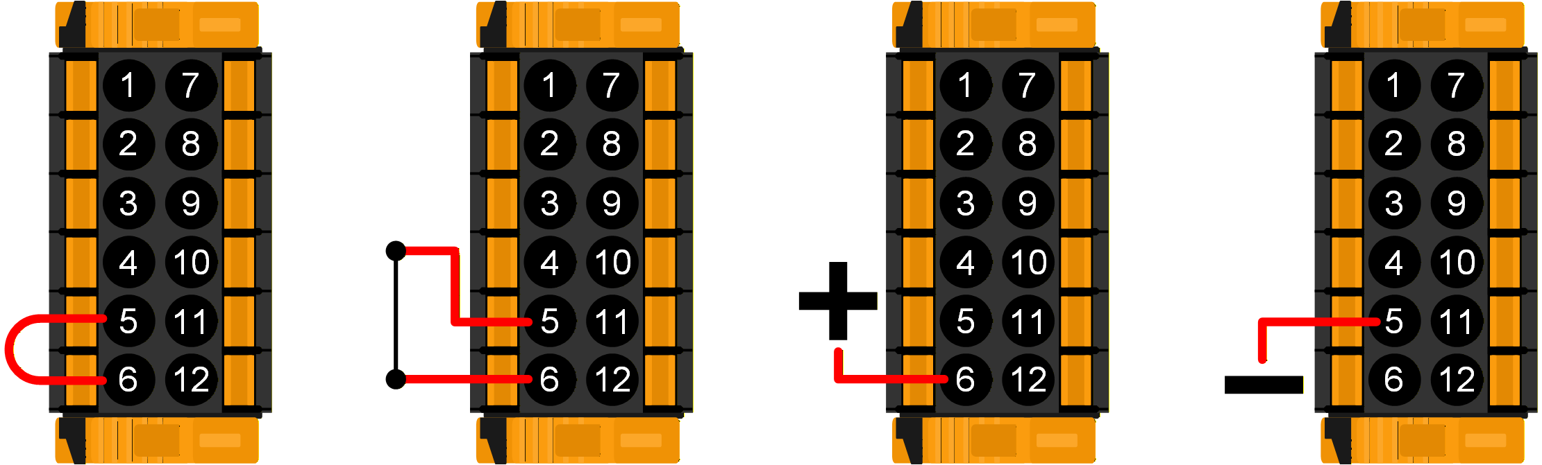 |
Il Multi RS Solar verrà spento se gli ingressi sono cablati in una delle quattro modalità raffigurate sulla destra.
| 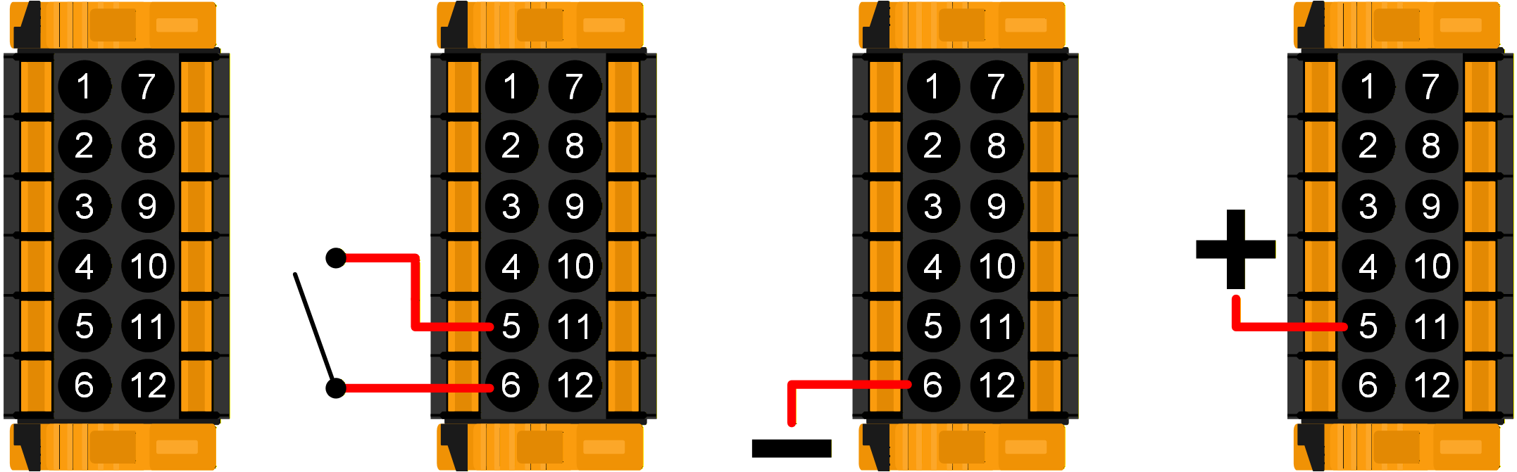 |
Modalità BMS a 2 cavi:
I terminali REMOTE_H e REMOTE_L possono anche essere configurati per l'interfacciamento con un BMS a 2 cavi. Due contatti separati sul BMS controllano se al Multi RS Solar è consentita la carica o la scarica. Tale impostazione può essere configurata in VictronConnect; vedere Modalità remota nel menu Impostazioni batteria.
Cambiare la modalità da "On/Off remoto" a "BMS a 2 cavi".
I seguenti diagrammi mostrano in quale modalità si troverà il Multi RS Solar in base dello stato dei terminali REMOTE_H e REMOTE_L.
Nota
In modalità BMS a 2 cavi, se i terminali REMOTE_H e REMOTE_L sono collegati (ma non a +48V), il Multi RS Solar sarà acceso, ma la carica sarà disattivata.
I contatti "Consenti carica" e "Consenti scarica" del BMS sono entrambi chiusi. I terminali REMOTE_H e REMOTE_L vengono entrambi portati a +48 V attraverso i contatti dell'interruttore BMS. Il Multi RS Solar funziona normalmente e può caricare e scaricare la batteria. | 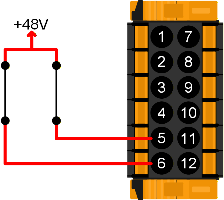 |
Il BMS ha aperto il suo contatto “Consenti carica”. REMOTE_H viene portato a +48 V attraverso il contatto BMS e il terminale REMOTE_L è a circuito aperto (flottante). Il Multi RS Solar smette di caricare la batteria da fonti CA e/o solari, ma continua a scaricare la batteria come di consueto. | 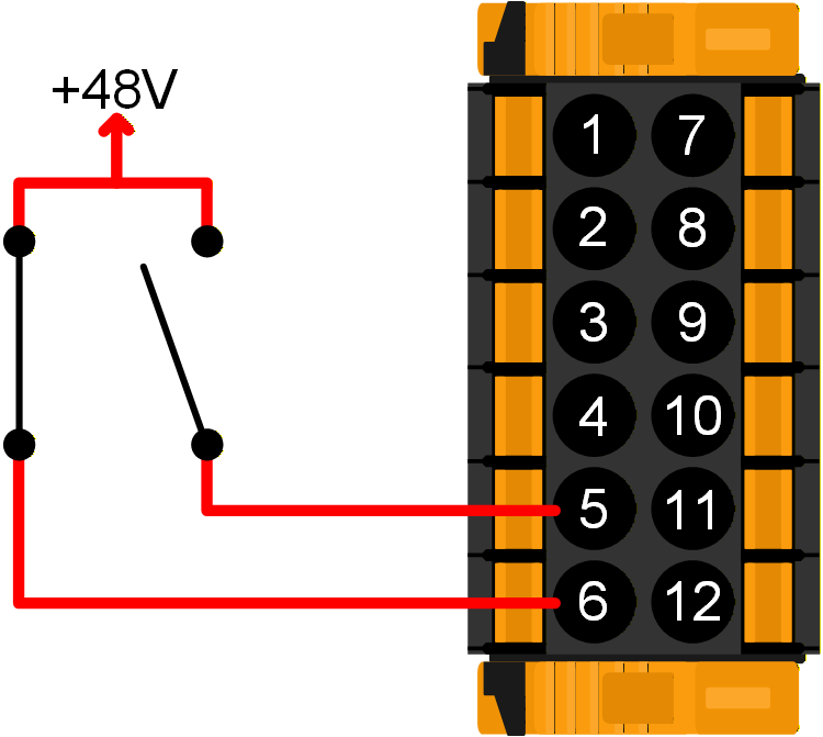 |
Il BMS ha aperto il suo contatto "Consenti scarica". Il terminale REMOTE_L viene portato a +48 V attraverso il contatto BMS e il terminale REMOTE_H è a circuito aperto (flottante). Il Multi RS Solar smette di scaricare la batteria, ma continua a caricarla da fonti CA e/o solari, se disponibili. | 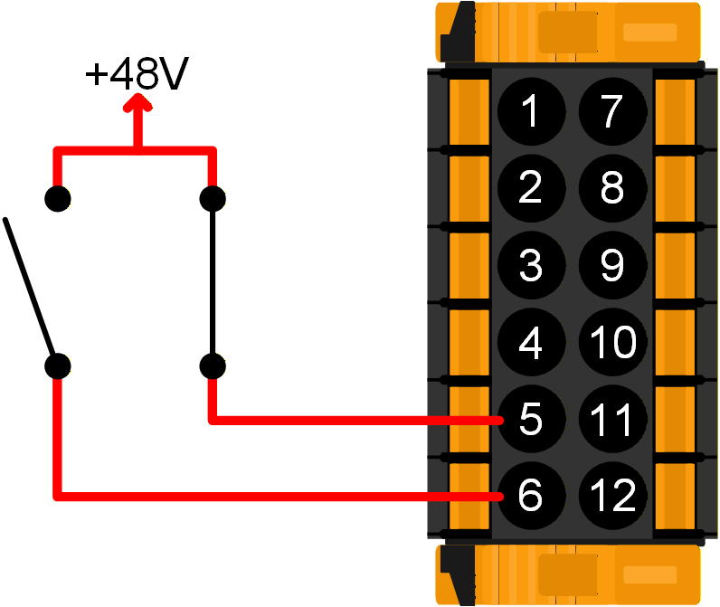 |
I contatti "Consenti carica" e "Consenti scarica" del BMS sono entrambi aperti. I terminali REMOTE_H e REMOTE_L sono entrambi a circuito aperto (flottanti). Non è consentito né caricare né scaricare, quindi il Multi RS Solar si spegne. | 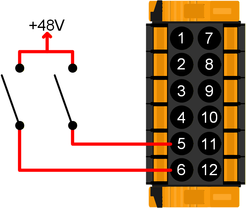 |
4.11.2. Relè programmabile
È presente un contatto relè generico a potenziale zero (secco) che può essere configurato per varie funzioni.
A tale fine, utilizzare il menu Relè di VictronConnect.
I contatti del relè sono dimensionati per 4 A fino a 35 VCC e 1 A a 70 VCC.
Avvertimento
Non utilizzare il contatto del relè per circuiti in CA (230 V).
In questo esempio, il contatto di relè normalmente aperto è configurato per l'avvio e l'arresto di un generatore. | 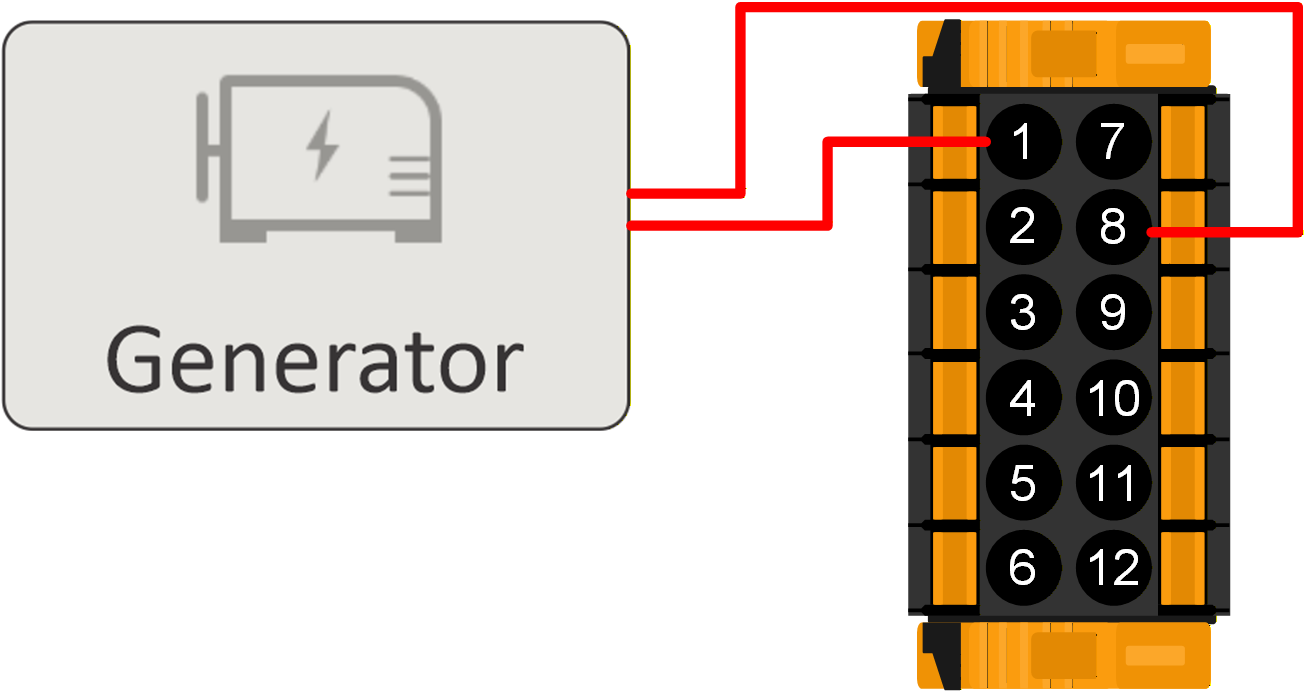 |
4.11.3. Sensore tensione
Per compensare le eventuali perdite lungo il cavo durante la carica, è possibile collegare due cavi di rilevamento direttamente alla batteria o ai punti di distribuzione positivo e negativo. Utilizzare un cavo con sezione trasversale di 0,75mm². Durante la carica della batteria, il caricabatterie compensa il calo di tensione lungo i cavi CC fino a un massimo di 1 Volt (ad es., 1 V sul collegamento positivo ed 1 V su quello negativo). Se il calo di tensione rischia di eccedere 1V, la corrente di carica viene limitata in modo da limitare anche il calo di tensione ad 1V.
Esempio di collegamento dei terminali VSENSE+ e VSENSE- ai morsetti della batteria. Si consiglia di installare un fusibile vicino alla batteria per proteggere i cavi di rilevamento della tensione da eventuali cortocircuiti. | 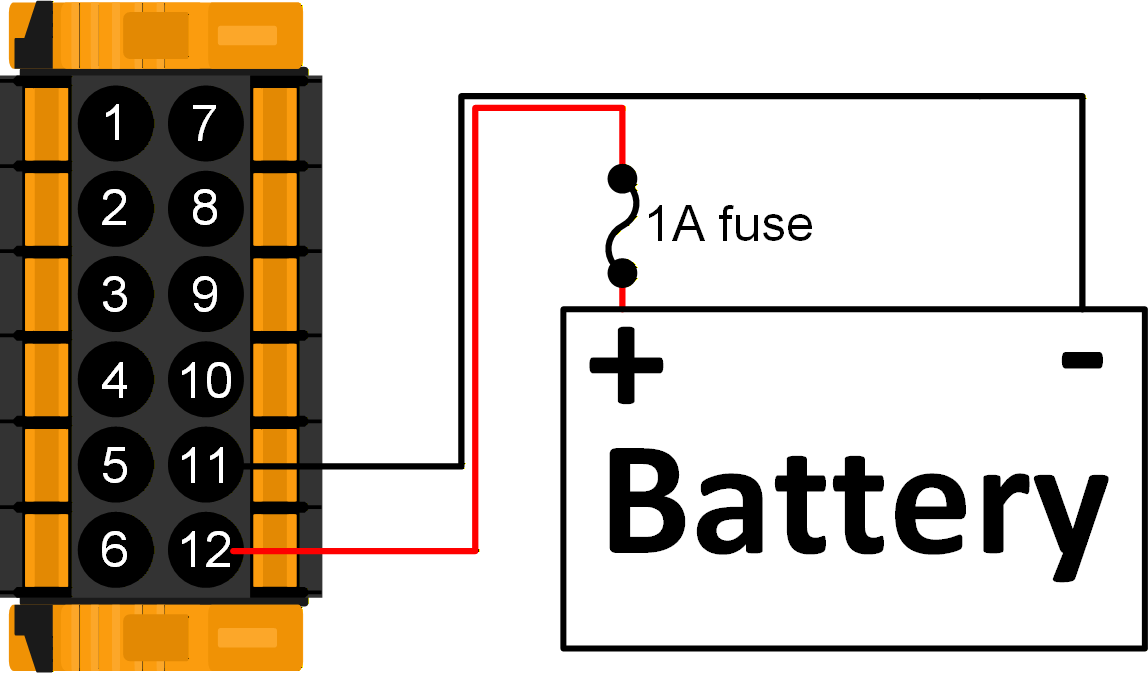 |
4.11.4. Sensore temperatura
Per una carica a compensazione di temperatura, è possibile collegare il sensore di temperatura (in dotazione con l’unità). Il sensore è isolato e deve essere montato sul morsetto negativo della batteria. Il sensore di temperatura può essere utilizzato anche per l'interruzione a causa di basse temperature durante la carica delle batterie al litio. Si può configurare nella pagina Impostazioni batteria di VictronConnect.
Il sensore di temperatura della batteria in dotazione è collegato al morsetto negativo della batteria. NotaUtilizzare esclusivamente il sensore di temperatura fornito con il Multi RS Solar. | 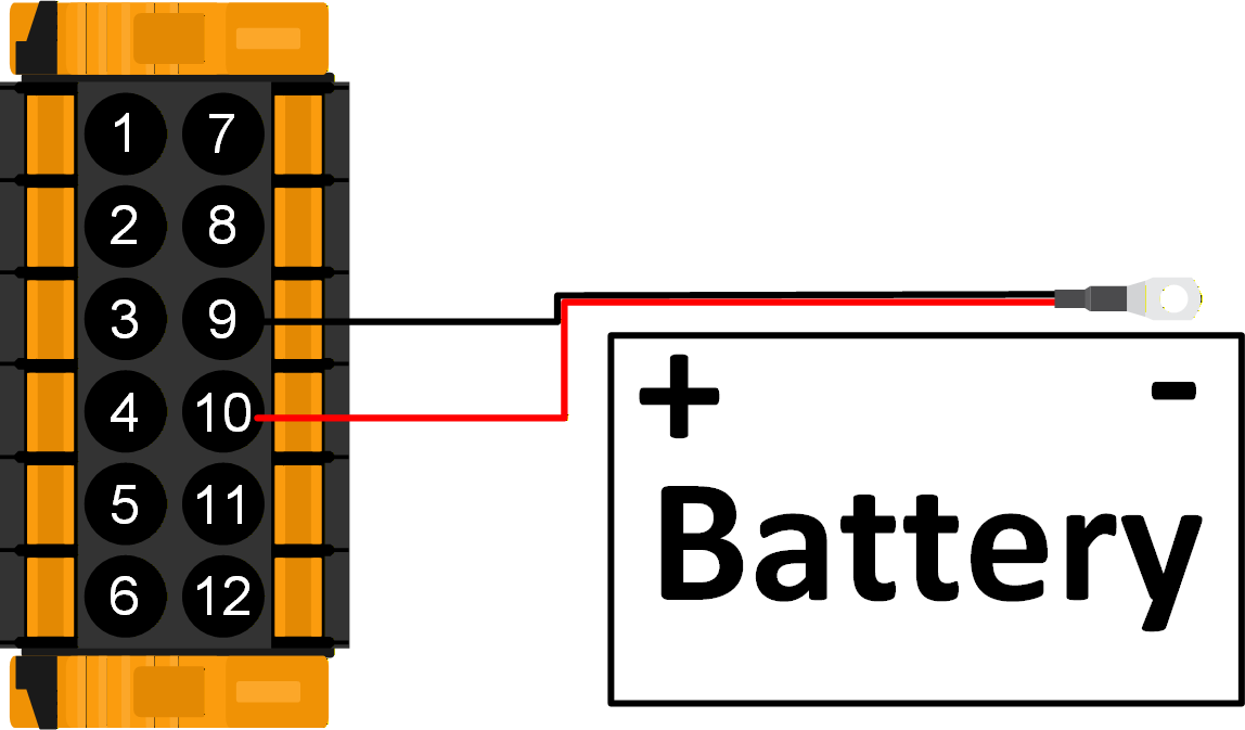 |
4.11.5. Ingressi ausiliari
Il modello Multi RS Solar è dotato di 2 porte di ingresso digitali, contrassegnate con AUX_IN1+ e AUX_IN2+ sulla morsettiera rimovibile, mentre AUX_IN- è il terminale comune per entrambe.
Un ingresso AUX_IN+ viene considerato attivo quando è collegato ad AUX_IN-.
Avvertimento
Non collegare alcun terminale AUX_IN al positivo o al negativo della batteria.
Il diagramma sulla destra mostra AUX_IN1 come attivo . | 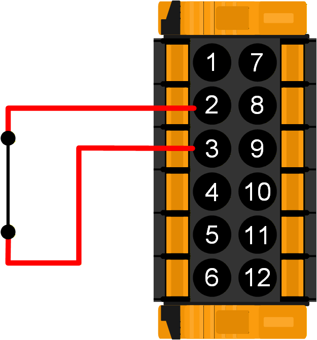 |
Il diagramma sulla destra mostra AUX_IN1 come inattivo . | 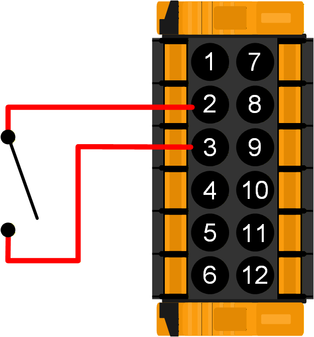 |
In VictronConnect, la pagina Impostazioni ingresso ausiliare consente di configurare diverse funzioni.
Non utilizzato: L'ingresso Aux non ha alcuna funzione.
Collegamento AC IN: L'ingresso CA può essere collegato o scollegato in base alle necessità. Ad esempio, è possibile disattivare l'ingresso CA durante i periodi di picco più costosi di una tariffa a tempo. Per impostare lo stato di collegamento dell'ingresso CA è possibile utilizzare un segnale attivo o un segnale inattivo.
Attivazione alimentazione AC IN: In un impianto parallelo alla rete, l'ingresso Aux può essere utilizzato per attivare o disattivare l'immissione in rete. Per impostare lo stato di immissione si può utilizzare un segnale attivo o un segnale inattivo.
Interruttore di sicurezza: Il Multi RS Solar funziona solo quando l'ingresso Aux è attivo.
Può essere utilizzato per spegnere da remoto il Multi RS Solar, se i terminali REMOTE_L e REMOTE_H sono configurati per un BMS a 2 cavi.
Può anche essere utilizzato come segnale di interruttore di sicurezza separato da un altro sistema che richiede un proprio ingresso.
Nota
Se i terminali REMOTE_L e REMOTE_H si trovano in uno stato che causa lo spegnimento del Multi RS Solar, la funzione dell'interruttore di sicurezza dell'ingresso ausiliare verrà ignorata e rimarrà spenta.
Ad esempio, se i terminali REMOTE_H e REMOTE_L sono aperti, il Multi RS Solar viene spento indipendentemente dallo stato dell'interruttore di sicurezza dell'ingresso ausiliare.
Se la stessa funzione è assegnata a entrambi gli ingressi ausiliari, questi saranno trattati come una funzione AND, pertanto dovranno essere entrambi attivi affinché la funzione sia riconosciuta come attiva.
Nota
Alcuni codici di rete richiedono l’utilizzo degli ingressi ausiliari per limitare la potenza di carica o per impedire l'esportazione. Tutte le funzioni del codice di rete sovrascrivono le funzioni definite nelle impostazioni dell'ingresso ausiliare e vengono disattivate in grigio.
4.12. Programmazione del generatore
Il Multi RS Solar possiede una tolleranza per le irregolarità dell'ingresso CA, come rapidi cambiamenti di frequenza o di tensione, al fine di migliorare l'affidabilità del collegamento ai generatori.
L'utilizzo di un generatore associato al Multi richiede la versione del firmware v1.11 o successiva.
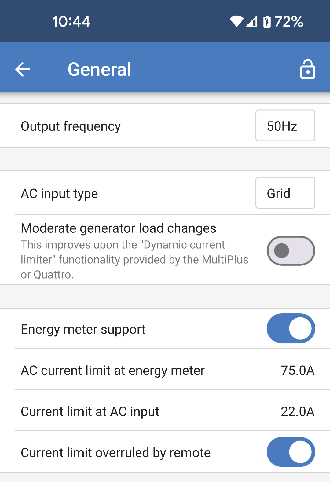
Impostare la seguente opzione nella pagina delle Impostazioni generali:
|
|
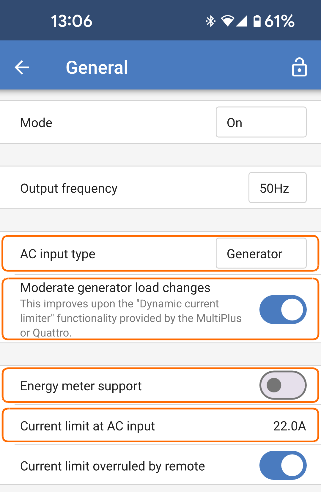
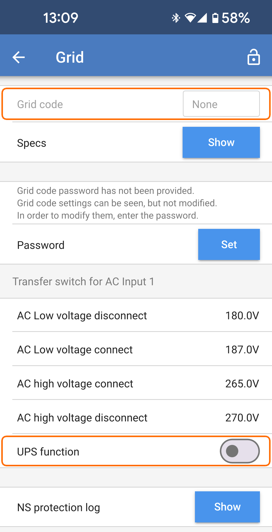
Se non è stato impostato alcun codice di rete, impostare quanto segue:
|
|
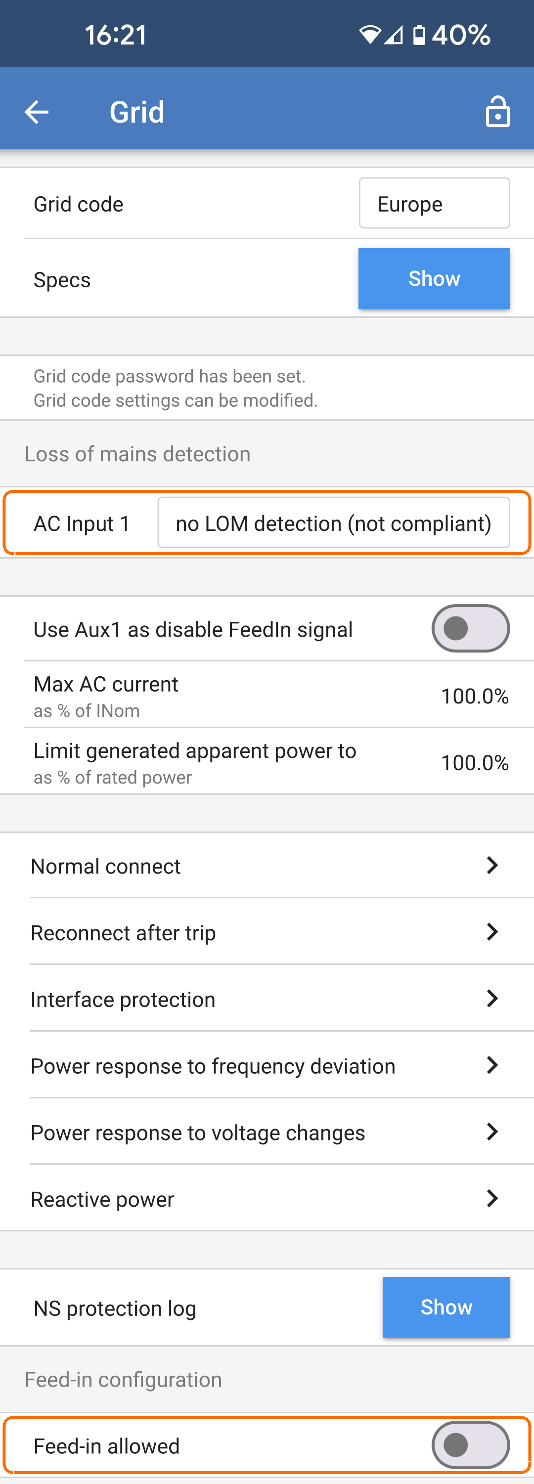
Se è stato impostato un codice di rete, impostare questi due parametri:
|
|
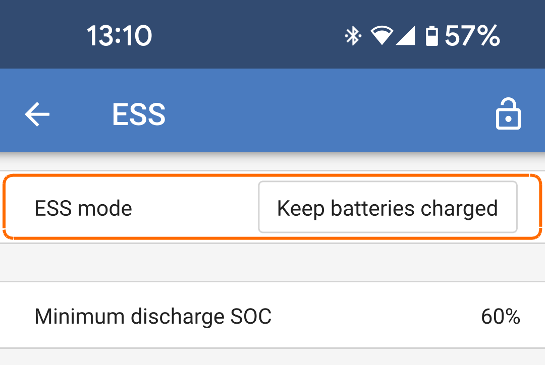
Assicurarsi che la modalità ESS sia impostata su "Mantieni le batterie cariche". |
|
È possibile utilizzare il contatto programmabile del relè del Multi RS Solar per avviare e arrestare un generatore. La configurazione è spiegata nella sezione VictronConnect.
I contatti dei relè sono presentati sul connettore I/O utente.
Per ulteriori limitazioni della potenza di carica, consultare il capitolo Limitazioni.
4.13. ESS- Sistema di Accumulo di Energia
Importante
Queste informazioni si riferiscono in particolare al modello "Dual Tracker" (PMR482602020).
L'immissione in rete di un Sistema di Accumulo di Energia non è supportata dal vecchio modello "Single Tracker" (PMR482602000).
Un sistema di accumulo di energia (ESS) è un tipo specifico di sistema di alimentazione che utilizza il Multi RS Solar per lavorare unitamente a una connessione alla rete. Viene utilizzato per ottimizzare l'uso dell'energia solare, l'accumulo delle batterie e l'importazione o l'esportazione dalla rete.
L'ESS può essere configurato per ottimizzare l'autoconsumo o per mantenere le batterie cariche.
Quando la potenza FV è superiore a quella necessaria per il funzionamento dei carichi, l'energia FV in eccesso viene immagazzinata nella batteria. L'energia immagazzinata viene poi utilizzata per alimentare i carichi nei momenti di carenza di potenza FV. Quando la batteria è piena, l'energia FV in eccesso può essere esportata in rete.
È possibile scegliere la capacità di riserva della batteria. Se la connessione alla rete è affidabile, è possibile utilizzare una quantità maggiore di energia proveniente dalla batteria e tenerne meno in riserva. Se la connessione alla rete è inaffidabile e subisce frequenti interruzioni, invece, sarebbe consigliabile conservare una maggior quantità di energia proveniente dalla batteria in riserva.
L'opzione "Mantieni le batterie cariche" consente di mantenere le batterie completamente cariche, se possibile. Le batterie si scaricano solo durante un'interruzione della rete, quando l'energia solare è insufficiente. Non appena torna la corrente di rete o è disponibile una quantità sufficiente di energia solare, le batterie si ricaricano automaticamente.
Nota
Non utilizzare le impostazioni dell’ESS in sistemi dotati di un generatore. Vedere la sezione Programmazione del generatore se il generatore è collegato all'ingresso CA.
Il Multi RS Solar può essere configurato come Sistema di Accumulo di Energia. In questa configurazione, il dispositivo funziona in modalità parallela alla rete, consentendo di immettere nuovamente energia in rete attraverso i terminali di ingresso CA.
Nota
Tutte le impostazioni ESS del Multi RS Solar si configurano in VictronConnect. Nel menu ESS sono disponibili opzioni di configurazione limitate per un dispositivo GX.
Per immettere in rete è necessario selezionare il codice di rete appropriato per il proprio Paese in VictronConnect. Nella maggior parte dei casi, prima di configurare un Sistema di Accumulo di Energia per l'immissione in rete è necessaria l'autorizzazione del gestore di rete.
Se non si dispone dell'autorizzazione del gestore di rete o se l'impianto non soddisfa i requisiti per l'immissione in rete, impostare il codice di rete su "Nessuno" In questo caso, l'energia non verrà reimmessa in rete.
Importante
La certificazione di immissione in rete del Multi RS Solar varia a seconda del Paese e attualmente non è certificata in tutti i Paesi.
Non dare per scontato che il dispositivo Multi RS Solar sia certificato o autorizzato all'esportazione in rete nel proprio Paese solo perché il suo codice di rete è elencato nel menu a discesa.
Verificare sempre la presenza di certificati aggiornati per questo prodotto, disponibili nella sezione Downloads e Assistenza del sito web.
Utilizzare VictronConnect per configurare il Multi RS Solar come ESS, come indicato di seguito:
Nella pagina delle impostazioni principali, selezionare la pagina delle impostazioni dell’ESS.
|
|
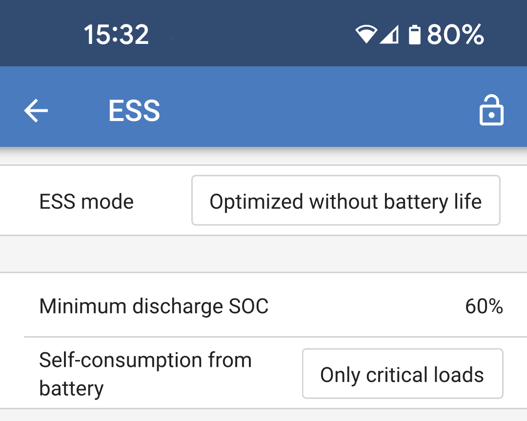
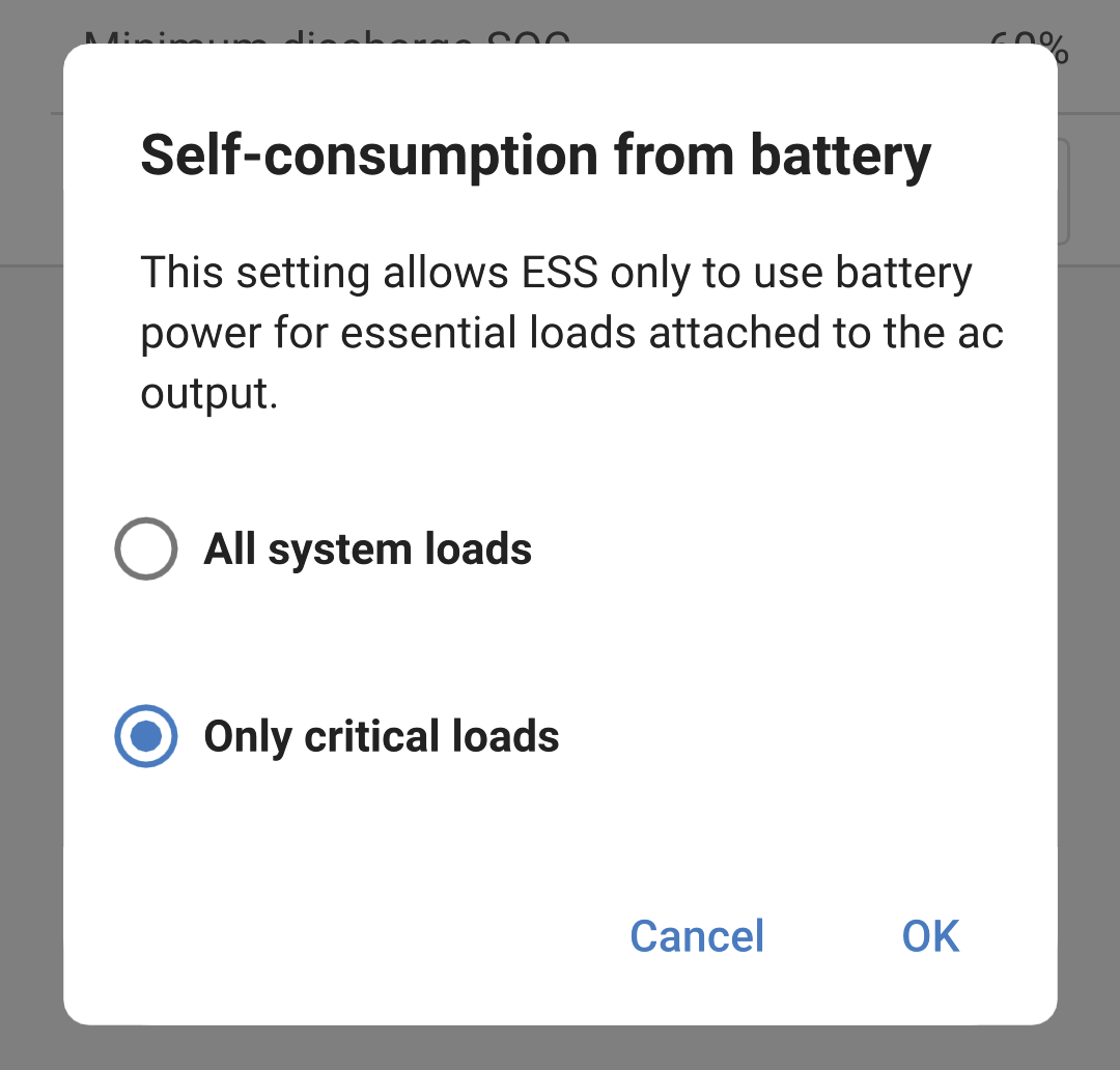
Opzioni dell’autoconsumo della batteria:
|
|
Nota
Le impostazioni del codice di rete richiedono una password per la protezione da interferenze non autorizzate.
Dopo aver impostato un codice di rete per la prima volta, non è possibile disattivarlo o modificarlo senza una password. Se fosse necessaria assistenza per modificare il codice di rete, contattare il proprio installatore.
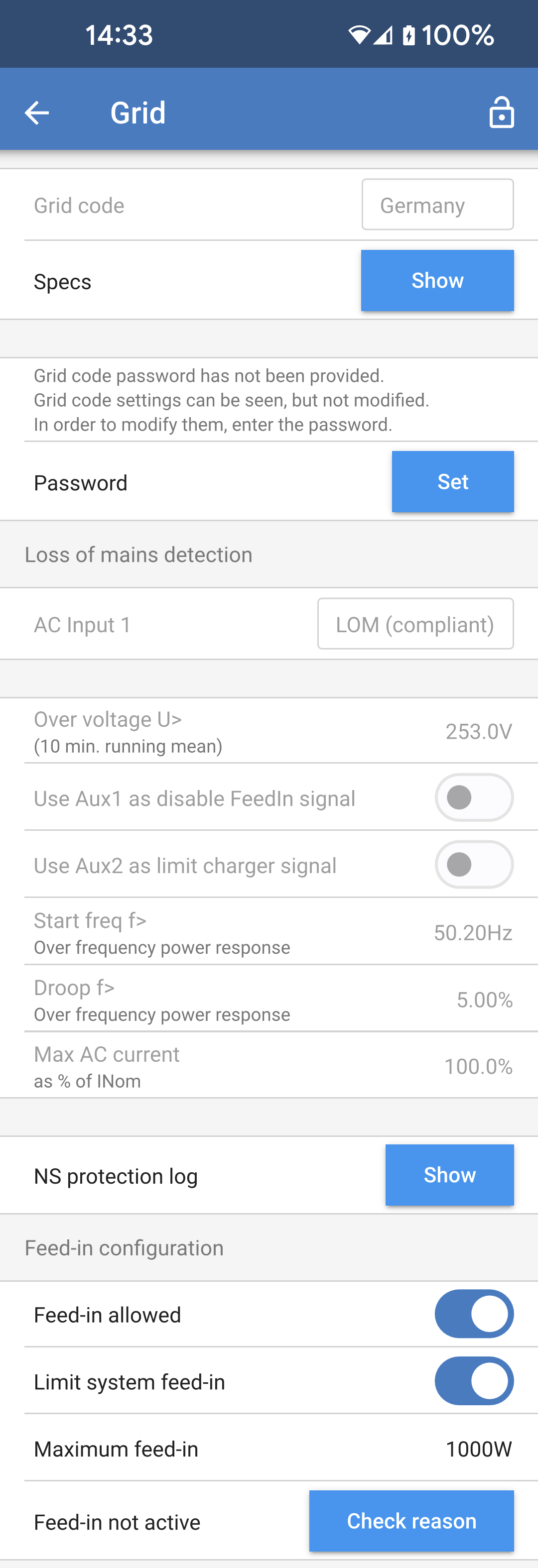
Entrare nella pagina delle Impostazioni di rete, scegliere un codice di rete appropriato per la propria ubicazione e selezionarlo. In base alla selezione effettuata, potrebbero diventare disponibili ulteriori opzioni, le quali possono variare a seconda della regione. Nell’esempio a continuazione, il codice di rete selezionato è quello della Germania. Alcune impostazioni appaiono in grigio e non possono essere modificate senza impostare la password del codice di rete. Attenzione a non modificare queste impostazioni se non su indicazione del gestore di rete.
Perdita del rilevamento dell’alimentazione di rete: In genere, la maggior parte di queste impostazioni appare in grigio e serve solo a scopo informativo. I valori sono definiti dal codice di rete selezionato.
Configurazione dell’immissione.
|
|
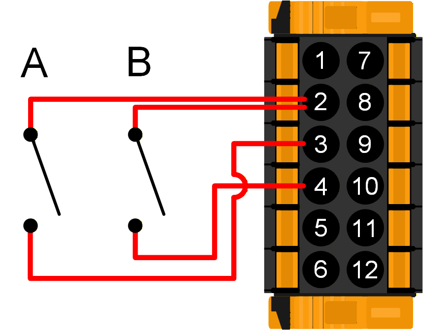
Se il codice di rete richiede il controllo esterno della potenza di carica o la disattivazione dell'immissione in rete, i contatti possono essere collegati ai terminali Aux_IN del connettore I/O utente. I sistemi trifase richiedono il cablaggio dei contatti su un solo connettore I/O dell'unità. Lo stato dei contatti viene quindi condiviso e replicato da tutte le altre unità del sistema. NotaNon tutti i codici di rete supportano l'uso di ingressi Aux. A titolo di esempio, per il codice di rete tedesco, i morsetti Aux_IN vengono utilizzati come segue:
|
|
4.14. Collegamento agli inverter FV CA esterni
Il Multi RS Solar è dotato di un sistema di rilevamento degli inverter FV CA integrato. Quando rileva un ritorno di FV CA (un’eccedenza) proveniente dalla porta di collegamento AC-out, il Multi RS Solar attiva automaticamente una regolazione della frequenza CA in uscita.
Sebbene non siano necessarie ulteriori configurazioni, è importante che l’inverter FV CA sia configurato correttamente per rispondere alla regolazione di frequenza riducendo la sua uscita.
Tenere presente che al Multi RS Solar si applica la scala 1:1 del dimensionamento dell’inverter FV CA e il dimensionamento minimo della batteria. Ulteriori informazioni riguardo queste limitazioni sono disponibili nel manuale Accoppiamento CA ed è necessario leggere tale documento se si utilizza un inverter FV CA.
L’intervallo di regolazione della frequenza non è configurabile e comprende un margine di sicurezza integrato. Quando si raggiunge la tensione di assorbimento, la frequenza aumenta. Di conseguenza, è ancora essenziale inserire un componente FV CC nell’impianto per ottenere una carica completa della batteria (ad es., fase mantenimento).
La frequenza di arresto dell'inverter FV (farresto) è di 53,2 Hz. Non è configurabile.
L’inverter FV CA potrebbe avere un’opzione per regolare la risposta dell’erogazione di potenza a varie frequenze.
La configurazione predefinita è stata testata e funziona in modo affidabile con il codice di configurazione di rete del Fronius MG50/60.
4.15. Configurazione dell’Inverter FV
Il Multi RS Solar può essere configurato come inverter FV anche in assenza di un banco batterie. Tutta l'energia FV viene immessa in rete attraverso il collegamento dell’ingresso CA.
Nota
Per utilizzare questa funzione il sistema deve essere collegato alla rete. È necessario impostare un codice di rete adatto alla propria posizione e disporre delle autorizzazioni necessarie per vendere energia alla rete.
Attenzione
Non collegare alcun carico o inverter FV esterno all'uscita CA 1.
Selezionare un codice di rete per la propria regione. Per ulteriori informazioni, vedere la pagina Impostazioni della rete.
Impostare la seguente opzione nella pagina Impostazioni ESS:
|
|
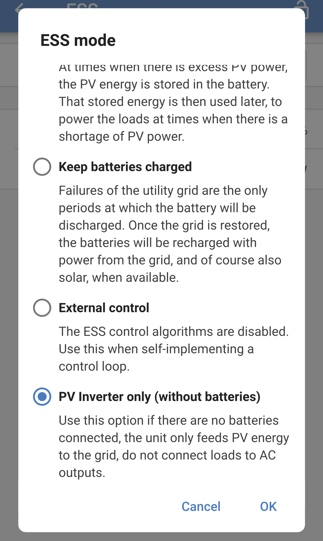
Dopo aver impostato la "Modalità solo inverter FV (senza batterie)", si attiveranno le seguenti impostazioni:
Sistema -> Configurazione del sistema = Autonomo
Generale -> Supporto contatore di energia = Disattivato
Controllo ingresso CA -> Collegamento ingresso CA condizionato = Disattivato
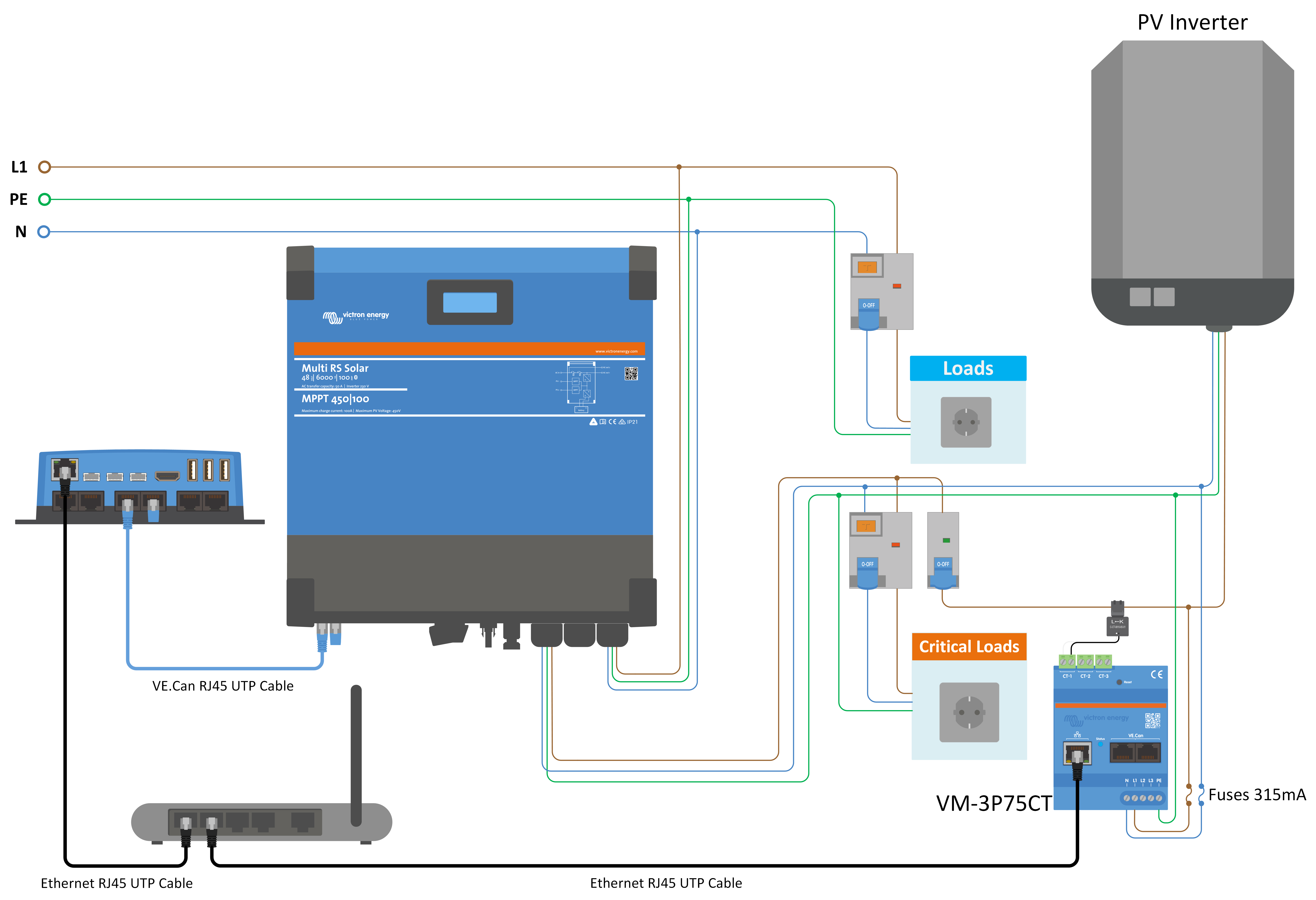
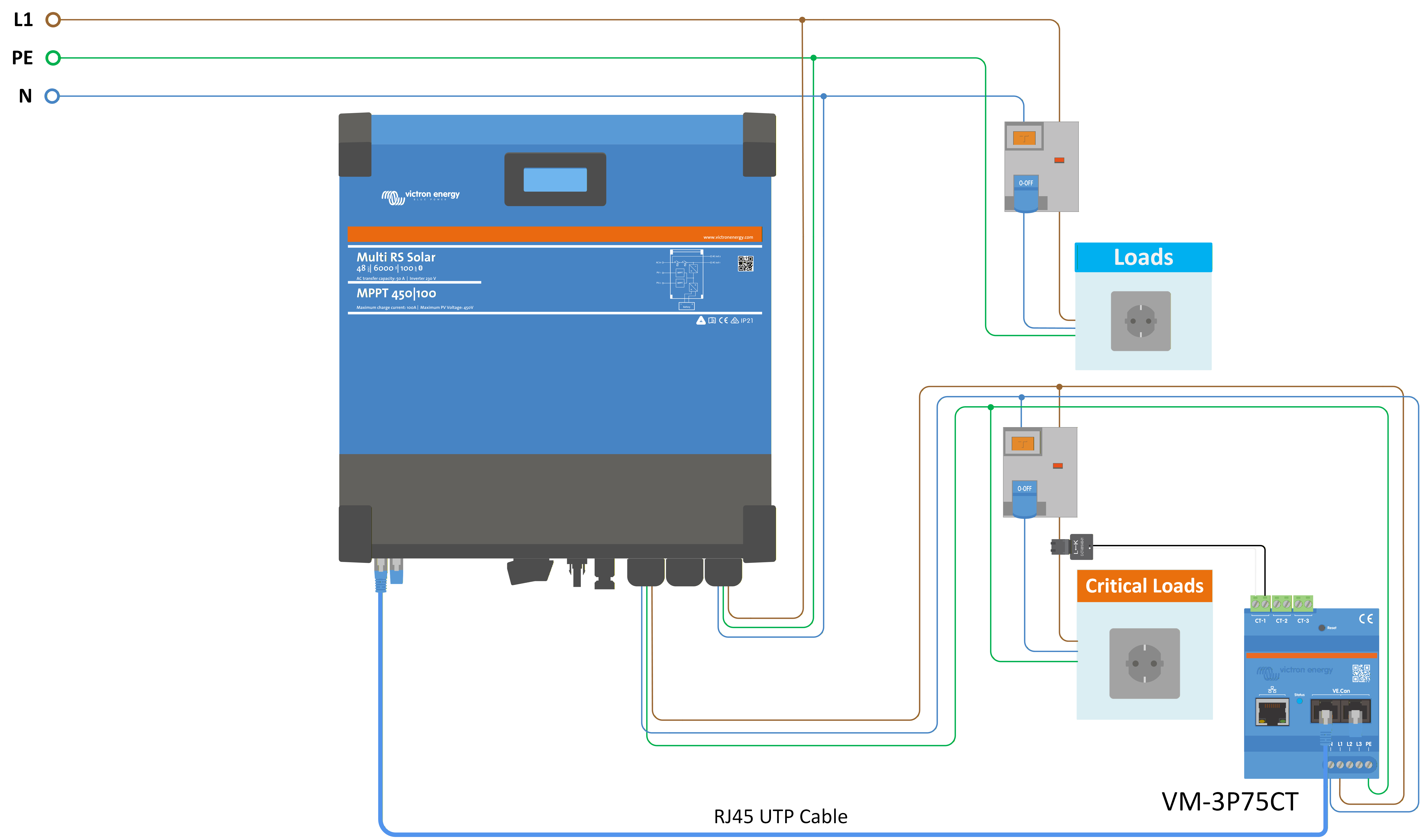
4.16. Collegamento di un contatore di energia esterno
Il Multi RS Solar è compatibile con il contatore di energia VM-3P75CT di Victron.
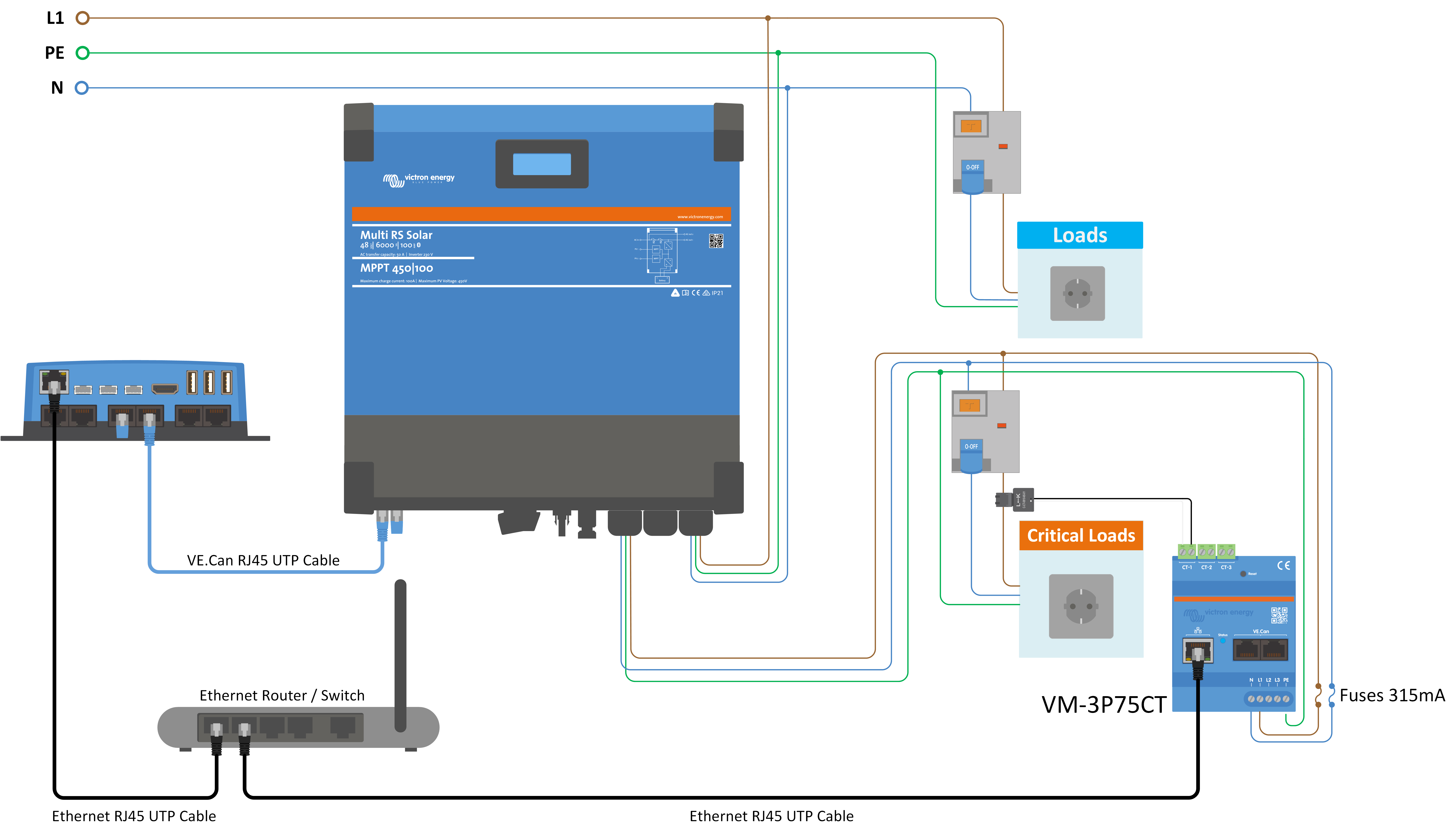
Il contatore di energia Victron può essere collegato tramite VE.Can o Ethernet. Per la connettività Ethernet è necessario un dispositivo GX. Vedere i diagrammi di esempio riportati di seguito.
Nota
Per la connettività Ethernet, il Multi RS Solar deve avere installata la versione firmware 1.26 o superiore.
Il dispositivo GX deve avere la versione 3.65 o superiore.
Avvertimento
Si devono evitare eventuali segmenti di rete WiFi tra il contatore di energia e il dispositivo GX a causa di problemi di latenza.
Utilizzare connessioni Ethernet cablate tra il contatore di energia, il router/switch e il dispositivo GX.
Per tutti i dettagli, consultare il manuale del VM-3P75CT.
Il contatore di energia può essere configurato per sistemi monofase o trifase.
Una volta selezionato il ruolo nelle impostazioni del contatore di energia, è possibile impostare il supporto del contatore di energia nelle impostazioni del Multi:
|
|
|
|
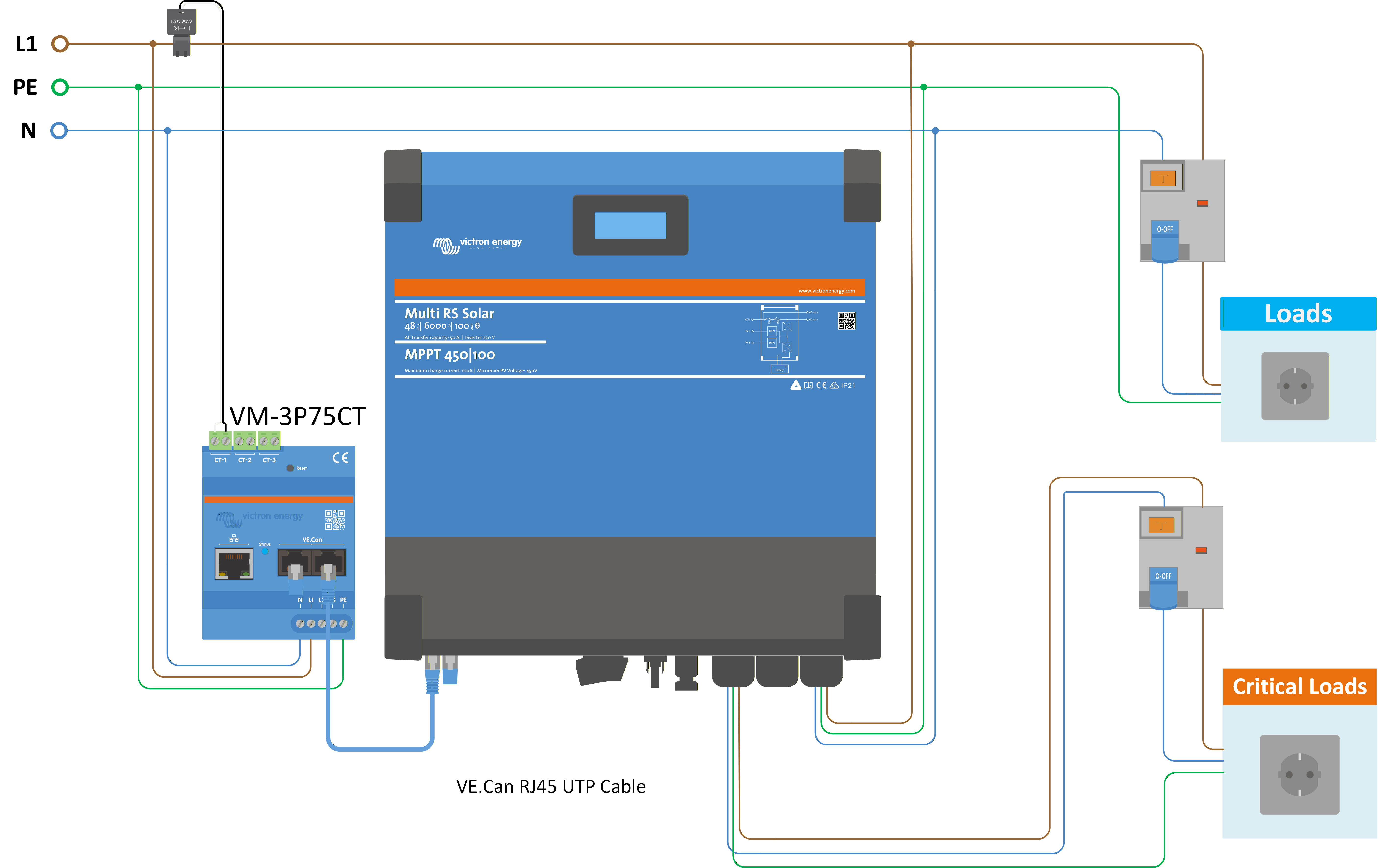
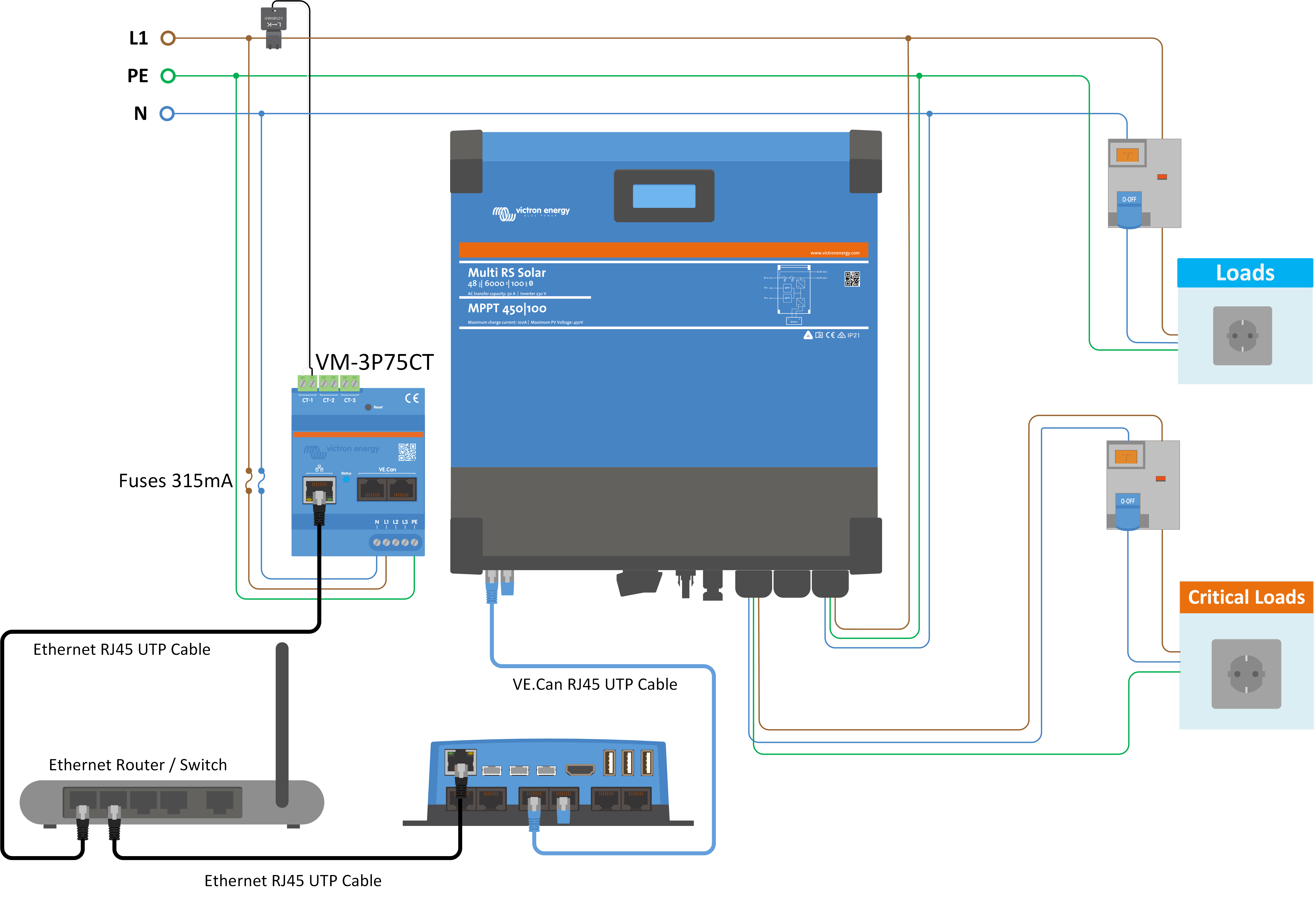
L'esempio di cablaggio sopra riportato può essere utilizzato quando il ruolo del contatore di energia è impostato come "Contatore di rete" o "Generatore". La corrente in ingresso dalla rete CA o da un generatore viene misurata prima dell'ingresso CA del Multi o di qualsiasi carico CA non critico.
Se è attivo “Assistenza contatori di energia”, è possibile impostare un limite di corrente nel contatore di energia, al fine di evitare un carico eccessivo in una rete CA debole. Se i carichi non critici superano il limite di corrente del contatore di energia, il Multi inizierà a "dare corrente" per cercare di mantenere il limite di corrente impostato.
|
|
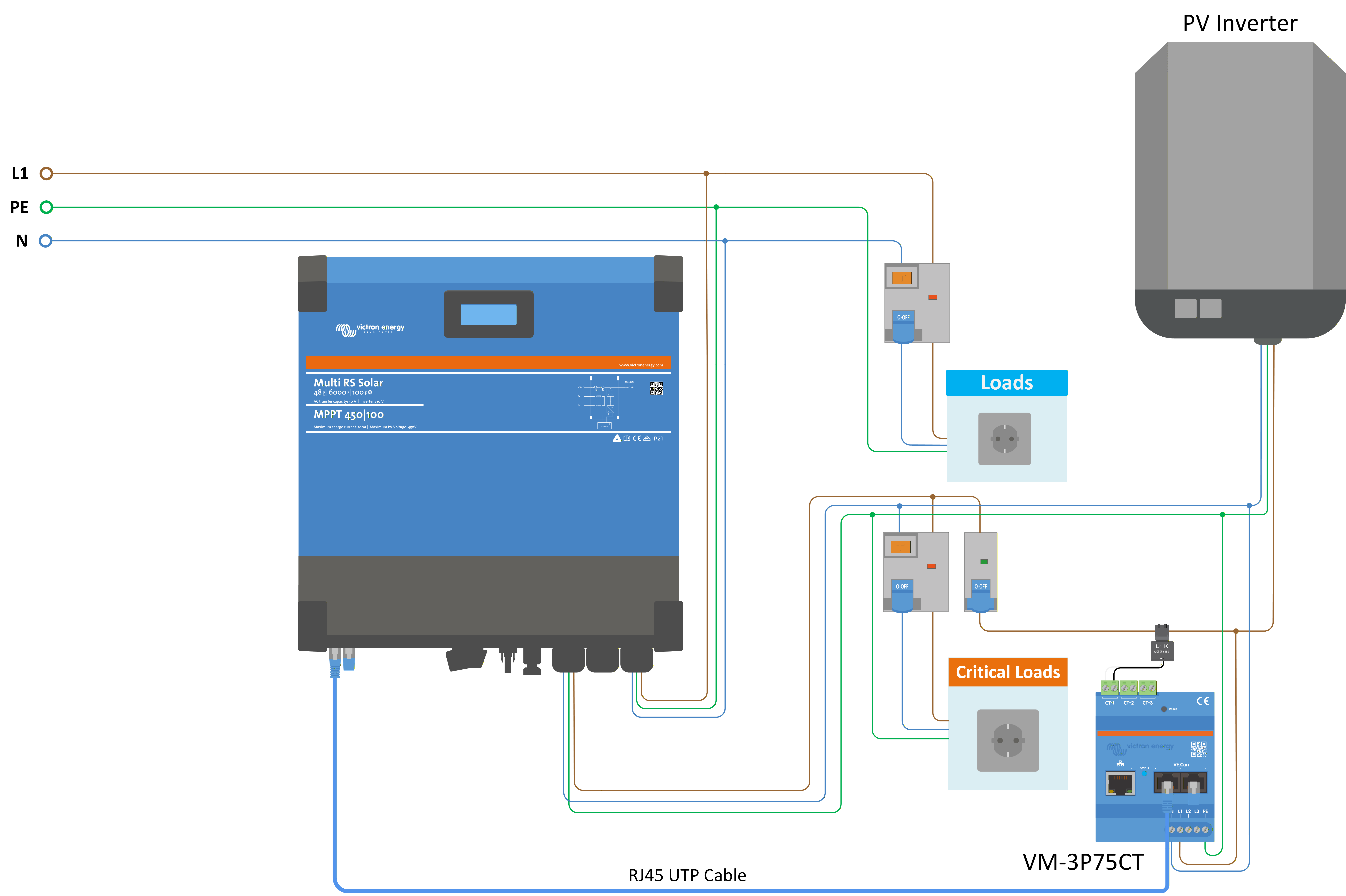
Se all'uscita CA del Multi è collegato un inverter FV generico, il ruolo del contatore di energia deve essere impostato su "Inverter FV" e cablato per misurare la corrente prodotta dall'inverter FV.
|
|
Se il ruolo del contatore di energia è impostato su "carico CA", il contatore di energia può essere cablato per misurare carichi specifici. Ad esempio, è possibile misurar il circuito di uno scaldabagno per monitorare il suo consumo energetico e tenere traccia della quantità di energia utilizzata.
4.17. Grandi sistemi - 3 fasi
Avvertimento
I sistemi trifase sono complessi. Non supportiamo né raccomandiamo che installatori non addestrati e/o inesperti lavorino su sistemi di queste dimensioni.
Se si è alle prime armi con Victron, invitiamo a iniziare con progetti di sistemi di piccole dimensioni, in modo da familiarizzarsi con la formazione, le apparecchiature e il software necessari.
Si raccomanda inoltre di affidare la progettazione e la messa in funzione a un installatore che abbia esperienza nella realizzazione di questi sistemi Victron più complessi.
Victron è in grado di fornire ai distributori una formazione specifica su questi sistemi tramite il loro responsabile regionale delle vendite.
Nota
La rete trifase VE.Can è diversa da quella VE.Bus. Si prega di leggere integralmente la documentazione, anche se si ha esperienza di grandi sistemi VE.Bus.
È possibile combinare diversi modelli di Inverter RS (ad esempio il modello con e quello senza solare). Tuttavia, la combinazione di Inverter RS e Multi RS non è attualmente supportata.
Cablaggio CC e CA
Ogni unità deve essere dotata di fusibili individuali sul lato CA e CC. Assicurarsi di utilizzare lo stesso tipo di fusibile per ogni unità.
L’intero sistema deve essere collegato a un unico banco batterie. Attualmente non supportiamo diversi banchi batterie collegati a un sistema trifase.
Cablaggio per la comunicazione
Tutte le unità devono essere collegate in cascata mediante un cavo VE.Can (RJ45 cat5, cat5e o cat6). La sequenza di tale collegamento non è importante.
Si devono utilizzare terminatori a entrambe le estremità della rete VE.Can.
Il sensore di temperatura può essere cablato a qualsiasi unità del sistema. Per un grande banco batterie è possibile cablare vari sensori di temperatura. Il sistema utilizzerà quello con la temperatura più alta per determinare la compensazione della temperatura.
Programmazione
Le impostazioni devono essere configurate manualmente modificando le impostazioni di ogni dispositivo. Tuttavia, alcune delle impostazioni relative al funzionamento trifase possono essere propagate ad altre unità mediante la Sincronizzazione impostazioni di sistema.
Le impostazioni del caricabatterie (limiti di tensione e corrente) vengono ignorate se è configurato il DVCC e se nel sistema è attivo un BMS-Can BMS.
Monitoraggio del sistema
Si raccomanda vivamente di utilizzare un prodotto della famiglia GX in combinazione con questi sistemi più grandi. Forniscono informazioni estremamente preziose sulla cronologia e sulle prestazioni del sistema.
Le notifiche di sistema sono presentate in modo chiaro e vengono attivate molte funzioni aggiuntive. I dati del VRM accelerano notevolmente l'assistenza, se necessaria.
4.18. Installazione trifase
Il Multi RS Solar supporta configurazioni monofase e trifase. Attualmente non supporta la fase divisa.
L'impostazione di fabbrica prevede il funzionamento autonomo, a unità singola.
Se si desidera programmare il funzionamento trifase, sono necessarie almeno 3 unità.
La dimensione massima del sistema supportata è di 3 unità in totale, con una singola unità su ciascuna fase.
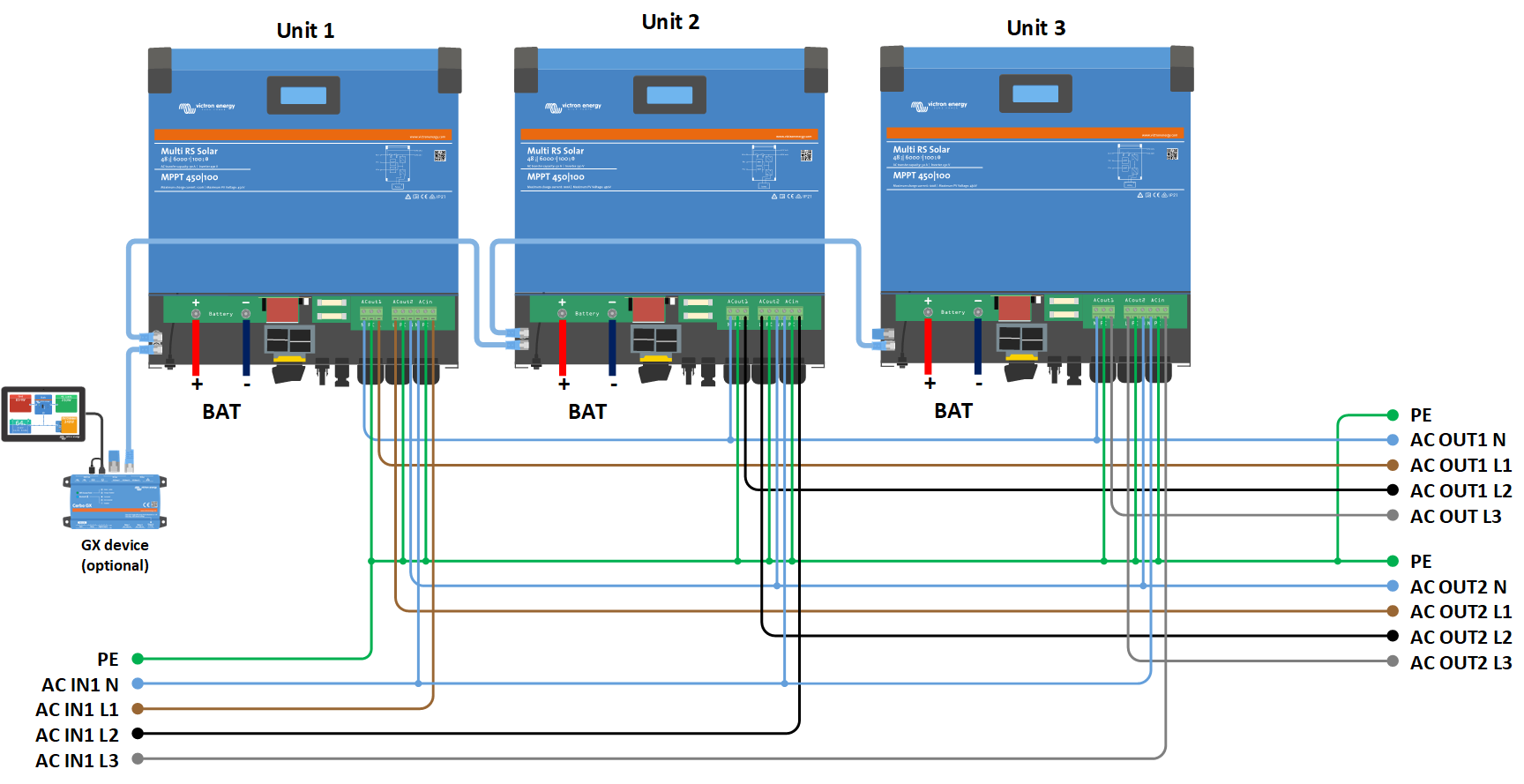
Devono essere collegati tra loro tramite connessioni VE.Can e deve essere presente un terminatore VE.Can all'inizio e alla fine del bus.
Una volta collegate alla batteria e tramite VE.Can, le unità dovranno essere configurate.
Configurazioni delta non supportate
Per le unità in configurazione trifase: I nostri prodotti sono stati progettati per una configurazione trifase a stella (Y). In una configurazione a stella tutti i neutri sono collegati, formando un cosiddetto “neutro distribuito”.
Non supportiamo una configurazione a delta (Δ). Una configurazione a delta non ha un neutro distribuito e comporta che alcune funzioni dell'inverter non rispondano come previsto.
4.19. Programmazione trifase
Per configurare un sistema trifase, il Multi RS Solar deve essere installato correttamente e avere la versione v1.13 o successiva del firmware.
La configurazione di un sistema per trifase o monofase si effettua in VictronConnect, nel menu Sistema.
Attenzione
L'alimentazione di uscita CA viene scollegata per alcuni secondi quando si passa alla modalità di configurazione del sistema. Assicurarsi che il sistema sia configurato PRIMA di collegare l'uscita CA dell'inverter ai carichi.
Nota
Queste Impostazioni di sistema devono essere programmate individualmente e impostate correttamente in tutte le unità collegate per ottenere un funzionamento sincronizzato.
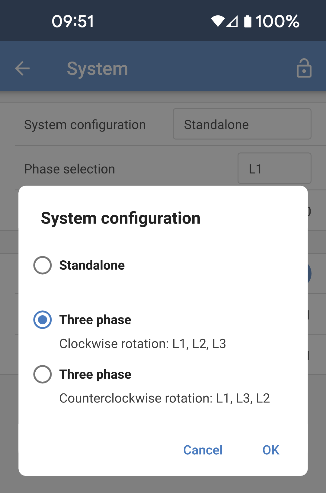
L'impostazione di fabbrica della configurazione del sistema è "Autonomo". Toccare la casella per visualizzare un menu a comparsa in cui è possibile selezionare "Trifase". È possibile scegliere tra due opzioni trifase, in senso orario o antiorario, a seconda della rotazione delle fasi nel luogo di installazione. È necessario applicare le stesse impostazioni a ogni singola unità. |
|
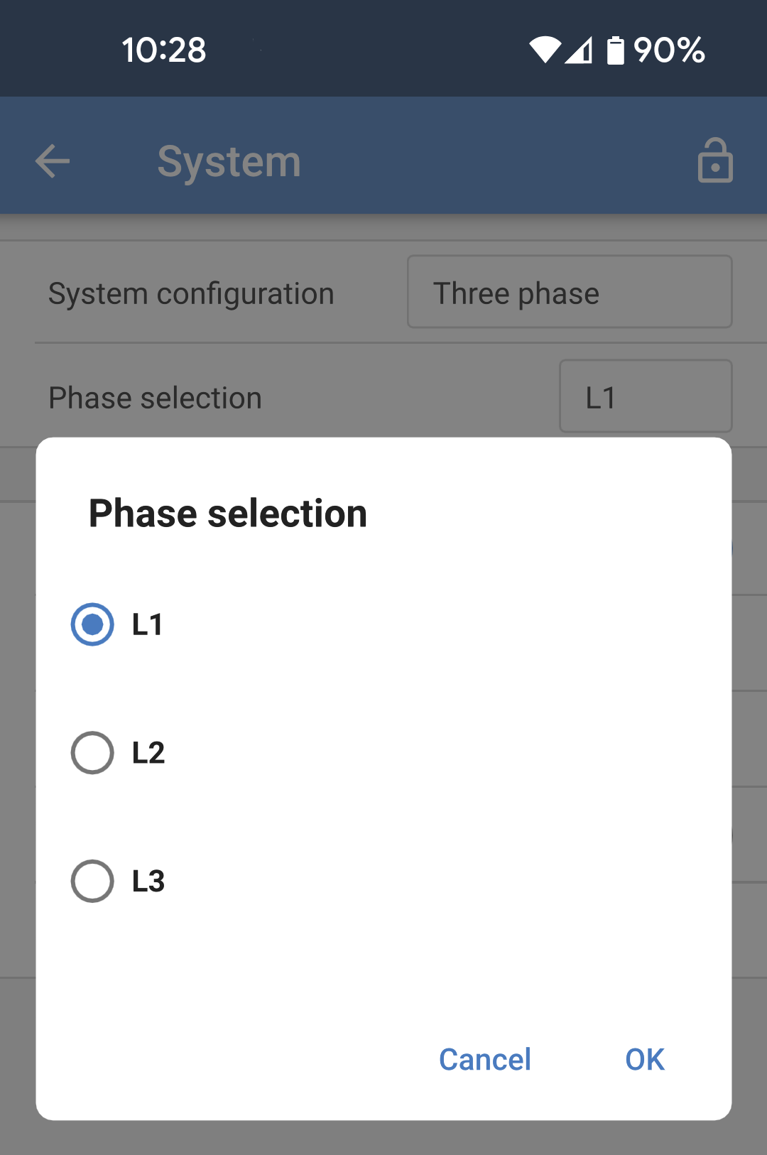
Selezionare la fase corretta a cui è collegata ogni unità. Può esserci una sola unità per fase. Eseguire questa operazione per ogni singola unità. È inoltre consigliabile etichettare fisicamente ogni unità e assegnare un nome personalizzato corrispondente nelle impostazioni delle informazioni sul prodotto. |
|
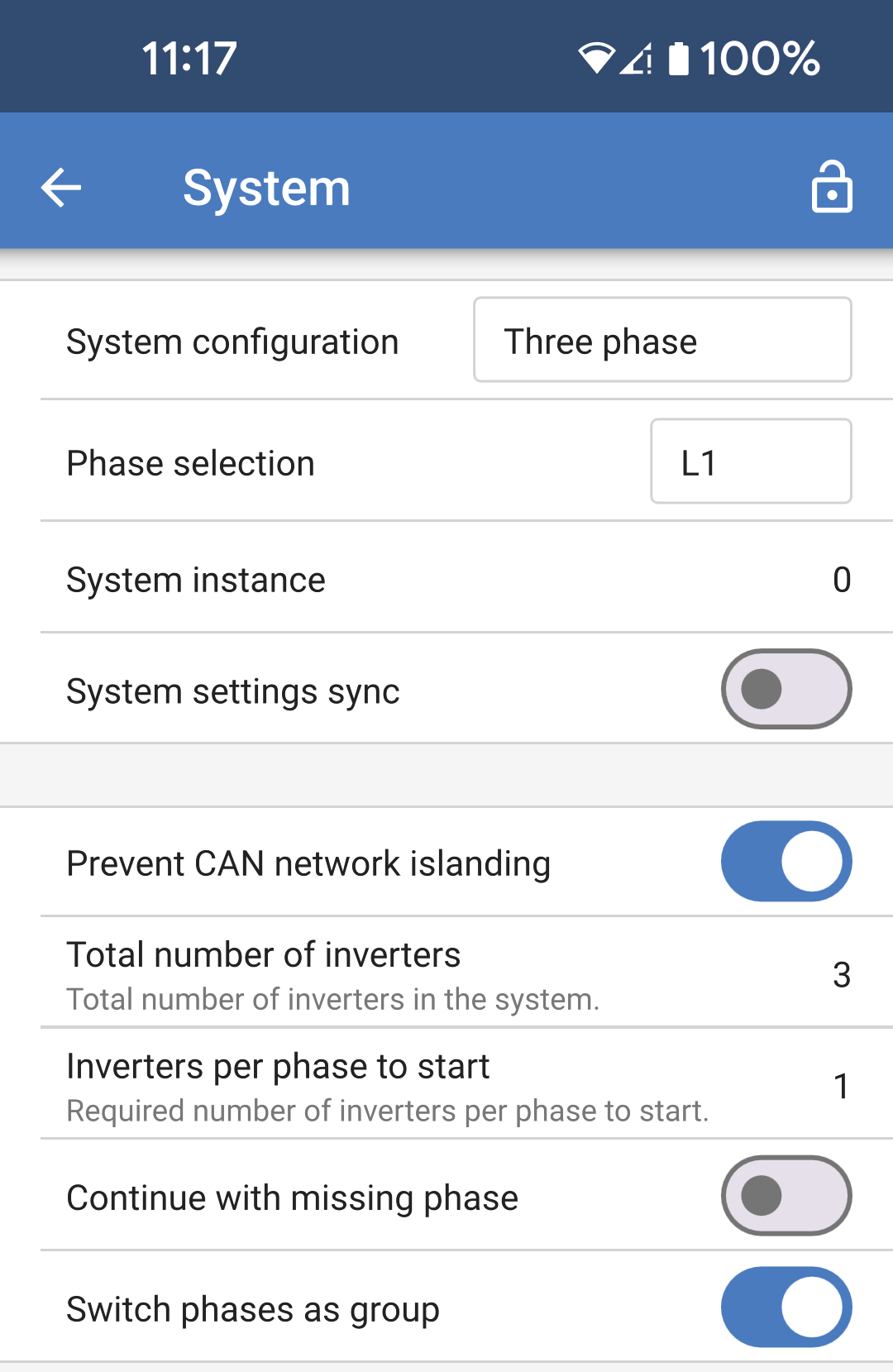
|
|
Nota sulla ridondanza e sull'uscita continua durante gli aggiornamenti del firmware
Il firmware di un sistema trifase può essere aggiornato senza perdere potenza sull'uscita CA.
Quando si avvia l'aggiornamento, accertarsi che sia disponibile un ingresso CA stabile; l'unità in corso di aggiornamento passerà alla modalità passthrough CA.
Il meccanismo di sincronizzazione CA utilizzato per la fase 3 possiede una versione "protocollo" incorporata.
Le unità possono funzionare insieme anche con versioni di firmware diverse, purché eseguano la stessa versione di protocollo.
Ciò consente un'alimentazione continua e ininterrotta anche durante l'aggiornamento del firmware, poiché le unità si aggiornano singolarmente una alla volta, mentre le altre continuano a sincronizzarsi e a fornire un'uscita CA stabile.
Se Victron ha bisogno di modificare il numero di versione del "protocollo", ciò sarà chiaramente indicato nel registro delle modifiche del firmware. Leggerlo sempre prima di aggiornare.
Nel caso in cui vi siano più versioni di protocollo in esecuzione sullo stesso bus VE.Can, le unità indicheranno l'errore #71 finché non saranno tutte aggiornate alla stessa versione.
Problemi conosciuti
In funzionamento trifase, la "funzione UPS" è troppo sensibile rispetto al funzionamento autonomo. Disattivare la "funzione UPS" nel caso in cui il Multi si scolleghi frequentemente dall'ingresso CA.
Quando il caricabatterie è in modalità controllata dalla tensione, le correnti di carica non sono ancora bilanciate tra le 3 fasi.