3. Features
3.1. Automatic battery voltage detection
The solar charger automatically detects supported (e.g 12V, or 24V) system voltage (battery voltage) on first power up. If a different system voltage is required at a later stage, or if the solar charger is connected to a 36V system, this can be manually configured in the solar charger settings.
3.2. Outstanding MPPT algorithm
Ultra fast MPP tracking
The solar charger contains an ultra fast MPPT controller. This is especially beneficial when the solar light intensity is constantly changing, as is the case during cloudy weather. Because of the ultra fast MPPT controller, 30% more energy is harvested compared to solar chargers with a PWM controller and up to 10% more compared to slower MPPT controllers.
Optimal solar yield
The solar charger has an innovative tracking algorithm. It will always maximize energy harvest by locking to the optimum MPP (Maximum Power Point). If partial shading occurs, two or more maximum power points may be present on the power-voltage curve. Conventional MPPTs tend to lock to a local MPP, which may not be the optimum MPP.
3.3. Outstanding conversion efficiency
The solar charger has an outstanding conversion efficiency. The maximum efficiency exceeds 98%. One of the benefits of the high efficiency is that the solar charger does not have a cooling fan and the maximum output current is guaranteed up to an ambient temperature of 40°C (104°F).
3.4. Extensive electronic protection
The solar charger is protected against over-temperature. The output is fully rated up to an ambient temperature of 40°C (104°F). Should the temperature further increase, the output current will be derated.
The solar charger is equipped with PV reverse polarity protection and PV reverse current protection.
3.5. VictronConnect app
The VictronConnect app can be used to:
Monitor the solar charger and view real-time solar and battery data.
Operate solar charger features.
Access up to 30 days of historical data and error history.
Configure solar charger settings.
Update firmware.
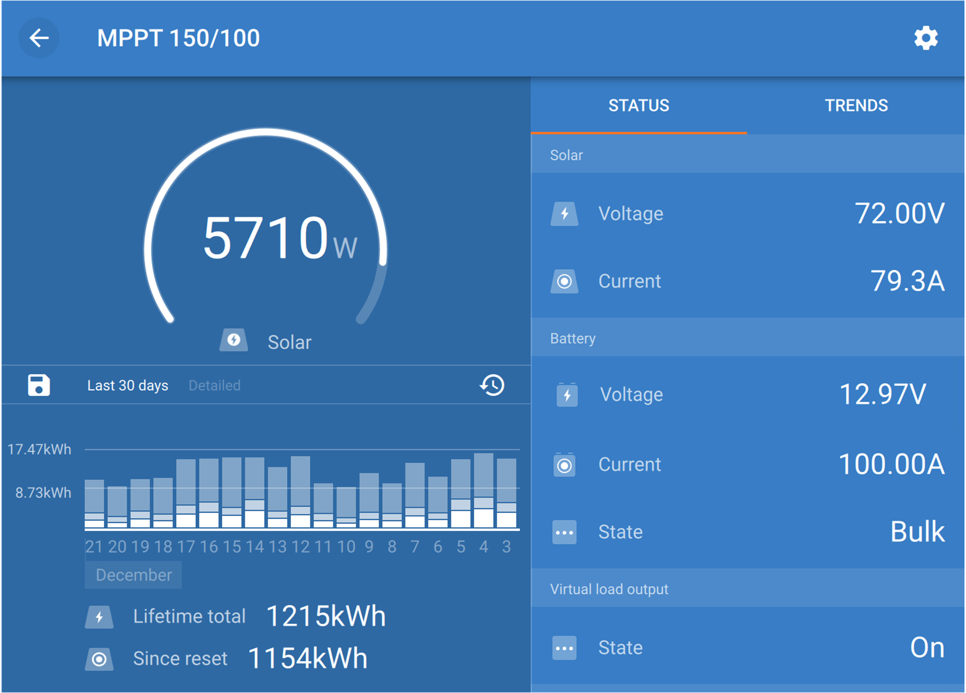 |
Screenshot of the VictronConnect app, showing real-time data and historical data.
The VictronConnect app can be downloaded from app stores or from the Victron Energy downloads page.
The app is available for the following platforms:
Android.
Apple iOS, note that USB is not supported, it is only possible to connect via Bluetooth.
MacOs.
Windows, note that Bluetooth is not supported, it is only possible to connect via USB.
 |
The app can connect to the solar charger in the following ways:
Directly via its built-in Bluetooth.
Via Bluetooth, using an optional VE.Direct Bluetooth Smart Dongle.
Via USB, using an optional VE.Direct USB interface.
Via internet or LAN, through the VRM portal, using an optional GX device or GlobalLink 520.
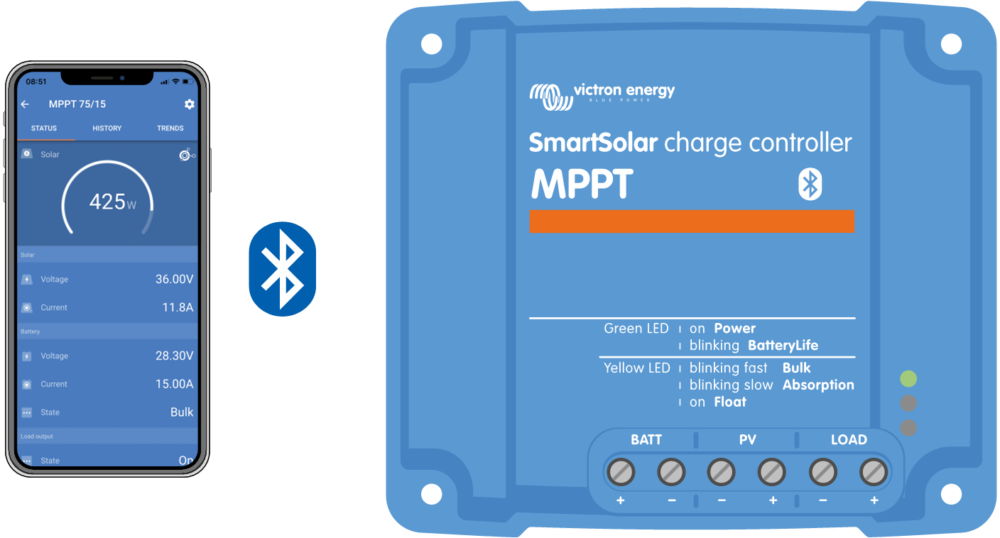
Connection via Bluetooth. | 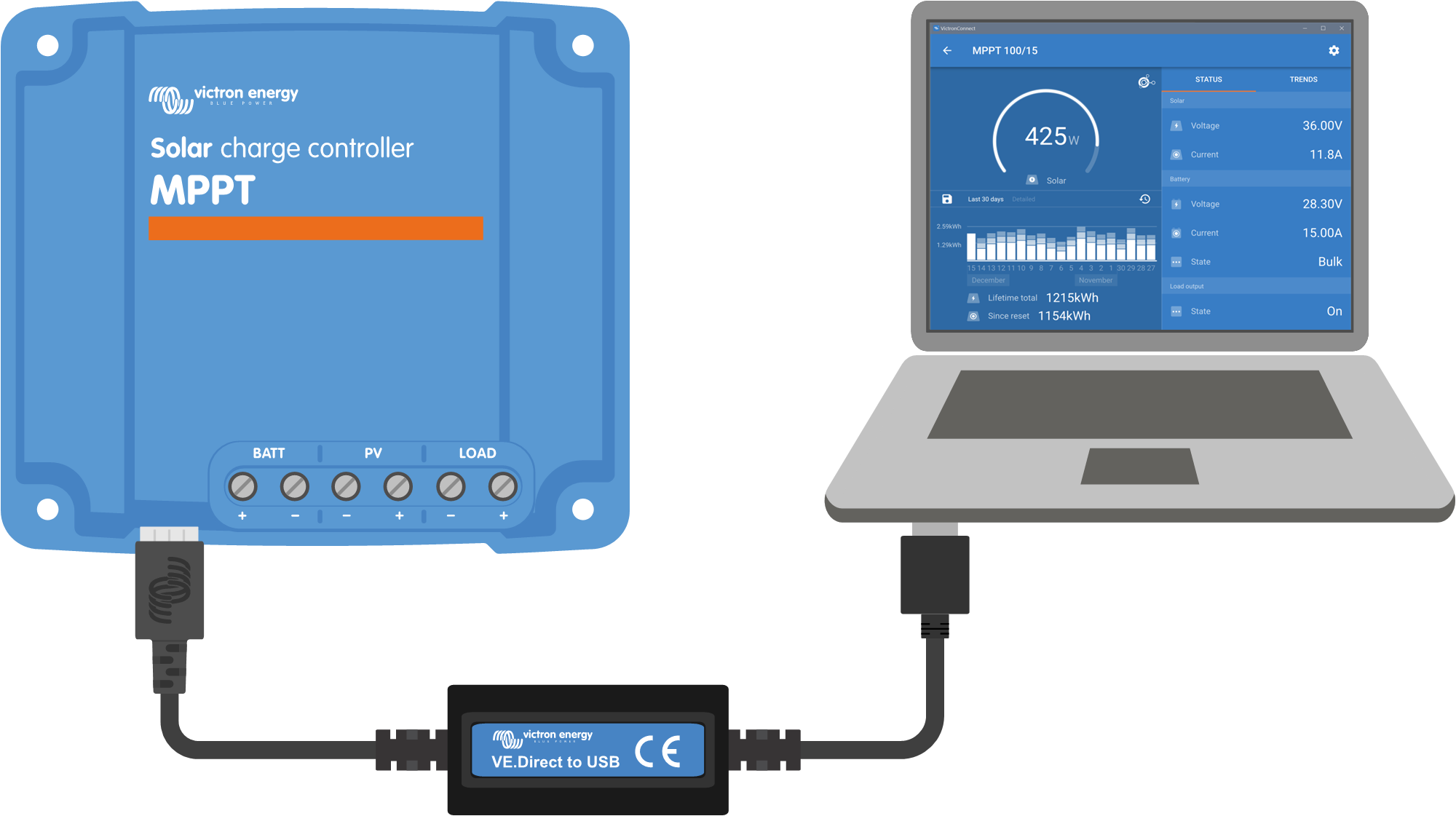 Connection via USB. | |
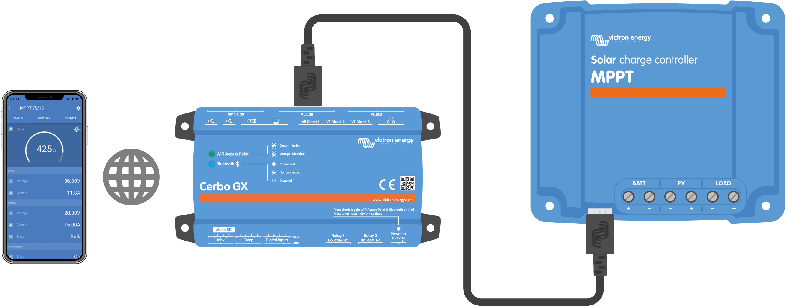 Connection via Internet or LAN. | ||
3.6. Display
There are a number of display options:
The VictronConnect app.
A GX device.
The VRM Portal, note that a GX device or a GlobalLink 520 is needed.
The MPPT Control - an (optional) external display that connects to the VE.Direct port. Note that the required VE.Direct cable is not included with the MPPT Control.
3.7. VE.Direct port
The VE.Direct port is used to communicate with the solar charger. It can be used for several purposes:
To connect to a monitoring device, such as a GX device or the GlobalLink.
To connect with the VictronConnect app.
For external control.
To program the load output behaviour.
Special cables or interfaces are needed to connect to this port:
VE.Direct cable - used to connect to a GX device or the GlobalLink.
VE.Direct to USB interface - used to connect via USB to the VictronConnect app.
VE.Direct Bluetooth Smart dongle - used to connect via Bluetooth to the VictronConnect app.
VE.Direct TX digital output cable - used for streetlight control or to create a virtual load output.
VE.Direct non inverting remote on/off cable - used to remotely switch the solar charger on or off.
3.8. Load output
The solar charger is equipped with a physical and virtual load output.
3.8.1. Physical load output
The DC loads in the system can be connected to the load output terminals. The solar charger controls the load output and disconnects the loads if the battery voltage drops too low, safeguarding the battery against too-deep discharges.
The disconnect voltage of the load output and the battery management algorithm can be configured via a jumper in the VE.Direct port or via the VictronConnect app. For more information refer to the Load output settings chapter.
The current rating of the load output is 15A or 20A (depending on the MPPT model) and is short-circuit proof.
Note
Note that the load output of the MPPT 100/20, when used in a 36 or 48V system, is only rated at 1A.
 |
Solar charger system with DC loads connected to the load output
Some loads, particularly inverters, have a higher current rating or high start-up current rating, exceeding the load output's capacity. These loads should be connected directly to the battery. The solar charger can still control these loads to prevent deep battery discharges by linking the load's remote on/off terminal to the solar charger load output. Depending on the load's on/off terminal type, a specific interface cable, such as an Inverting remote on/off cable , might be necessary.
 |
Solar charger system with inverter connected directly to the battery and controlled by the load output
Alternatively, a BatteryProtect can be used to control the load.
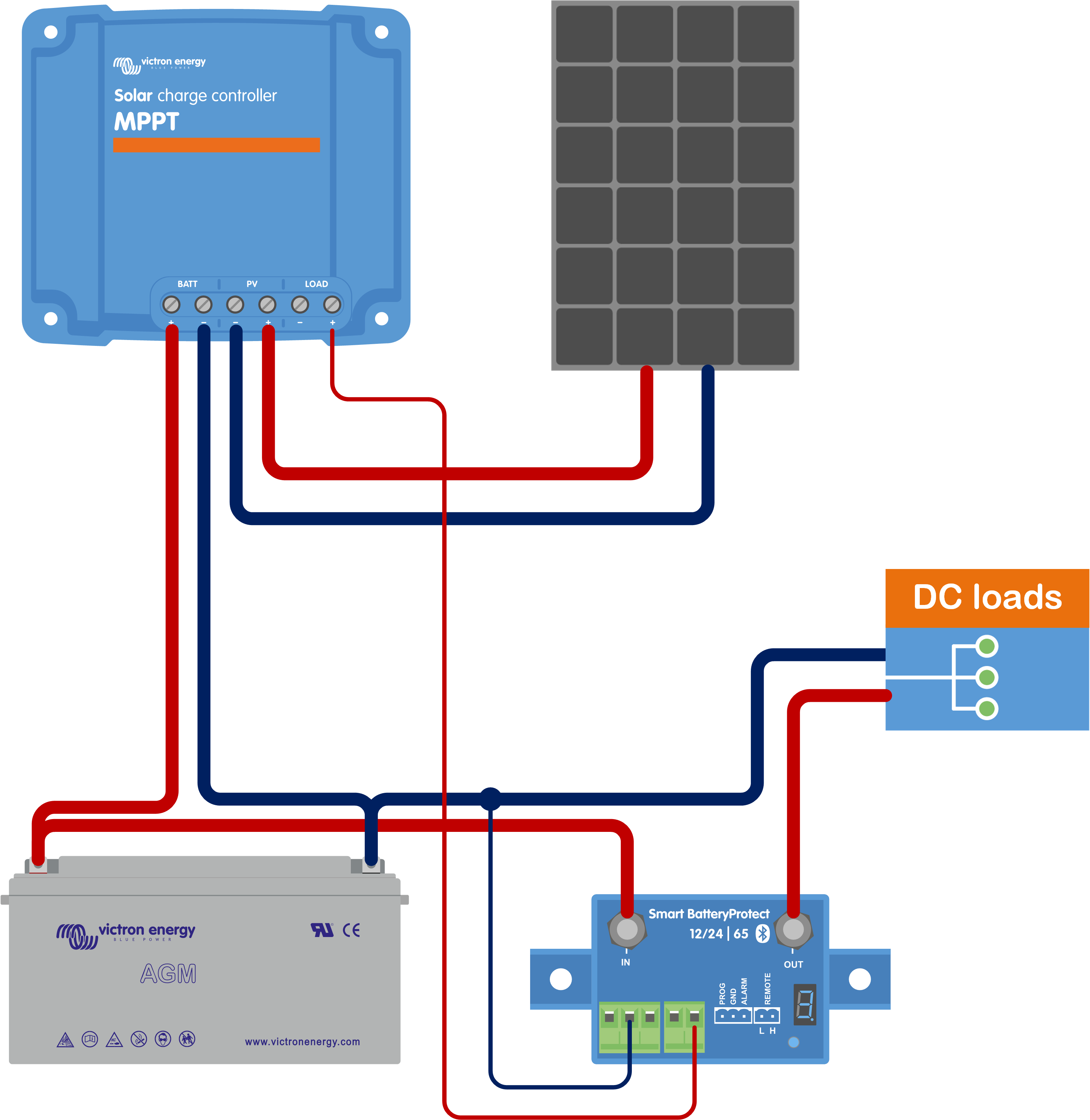 |
Solar charger system with DC loads connected directly to the battery via a BatteryProtect controlled by the load output
3.8.2. Virtual load output
A virtual load output can be established to control loads with current ratings greater than the solar charger's load output.
Use the VE.Direct TX cable and enable it to act as a virtual load output via the VictronConnect App RX port function. Refer to the RX port settings chapter.
The virtual load output can be set up within the VictronConnect app and controlled using battery voltages or the BatteryLife algorithm. For details on the configuration process, please consult the Load output settings chapter.
3.8.3. BatteryLife
When the solar charger is not able to recharge the battery to its full capacity within one day, the result is often that the battery will continually be cycled between a ‘partially charged’ state and the ‘end of discharge’ state. This mode of operation (no regular full recharge) will destroy a lead-acid battery within weeks or months.
The BatteryLife algorithm will monitor the state of charge of the battery and, if needed, day by day slightly increase the load disconnect level (i.e. disconnect the load earlier) until the harvested solar energy is sufficient to recharge the battery to nearly the full 100%. From that point onward, the load disconnect level will be modulated so that a nearly 100% recharge is achieved about once every week.
3.9. Battery charging
3.9.1. Adaptive 3-stage battery charging
The solar charger is a 3-stage charger. The charge stages are: Bulk – Absorption – Float.
Bulk
During the bulk stage, the solar charger delivers the maximum charge current, to rapidly charge the batteries. During this stage, the battery voltage will slowly increase. Once the battery voltage has reached the set absorption voltage, the bulk stage stops and the absorption stage commences.
Absorption
During the absorption stage, the solar charger has switched to constant voltage mode. The current flowing to the battery will gradually decrease. Once the current has dropped below 1A (tail current), the absorption stage stops and the float stage will commence.
When only shallow discharges occur the absorption time is kept short. This is to prevent overcharging of the battery. But if the battery was deeply discharged, the absorption time is automatically increased, to make sure that the battery is fully recharged.
Float
During the float stage, the voltage is reduced, and the battery's fully charged state is maintained.
Tip
A storage stage is not needed for solar chargers, unlike for AC chargers, since at night there is no solar power, so battery charging will stop.
3.9.2. Flexible charge algorithm
The VictronConnect app allows selection of 8 pre-set charge algorithms, or alternatively the charge algorithm is fully programmable. The charge voltages, stage duration and the charge current can be customized.
3.9.3. Equalization charging
Some lead-acid battery types need a periodic equalization charge. During equalization the charge voltage will be increased above the regular charge voltages to achieve cell balancing.
If an equalization charge is required it can be enabled using the VictronConnect app.
3.10. Temperature sensing
Temperature sensing allows for temperature compensated charging. The absorption and float charge voltages are adjusted based on either the battery temperature (accessory needed) or otherwise on the solar charger internal temperature.
Temperature compensated battery charging is needed when charging lead-acid batteries in hot or cold environments.
The temperature compensation can be enabled or disabled in the solar charger settings and the amount of compensation, the compensation coefficient (mV/°C), is adjustable.
3.10.1. Internal temperature sensor
The solar charger has a built-in internal temperature sensor.
The internal temperature is used to set the temperature compensated charge voltages. For this, the internal temperature when the solar charger is "cold" is used. The solar charger is "cold" when there is only little current flowing into the battery. Be aware that this is only an estimation of the ambient and the battery temperature. Should a more accurate battery temperate be needed, consider using an external battery temperature sensor, see chapter External temperature and voltage sensor.
The temperature compensation range is 6°C to 40°C (39°F to 104°F).
The internal temperature sensor is also used to determine if the solar charger is overheated.
3.10.2. External temperature and voltage sensor
The (optional) Smart Battery Sense is a wireless battery voltage and temperature sensor and can be used with the solar charger. It measures the battery temperature and the battery voltage and sends this via Bluetooth to the solar charger.
The solar charger uses the Smart Battery Sense measurements for:
Temperature compensated charging using the actual battery temperature, rather than the solar charger's internal temperature. An accurate battery temperature measurement will improve charging efficiency and prolong the life of lead-acid batteries.
Voltage compensation. The charge voltage is increased to compensate in case there is a voltage drop over the battery cables during high current charging.
The solar charger communicates with the Smart Battery Sense via Bluetooth using a VE.Smart Network. For more detail on the VE.Smart network see the VE.Smart Networking manual.
Alternatively, a VE.Smart Network that measures battery temperature and battery voltage, can also be set up between a solar charger and a BMV-712 Smart or SmartShunt battery monitor that has been equipped with a Temperature sensor for BMV, without the need for a Smart Battery Sense.
Note
Note that a VE.Smart Network can only be set up if the solar charger is capable of Bluetooth communication, has Bluetooth enabled or is equipped with a VE.Direct Bluetooth Smart dongle.
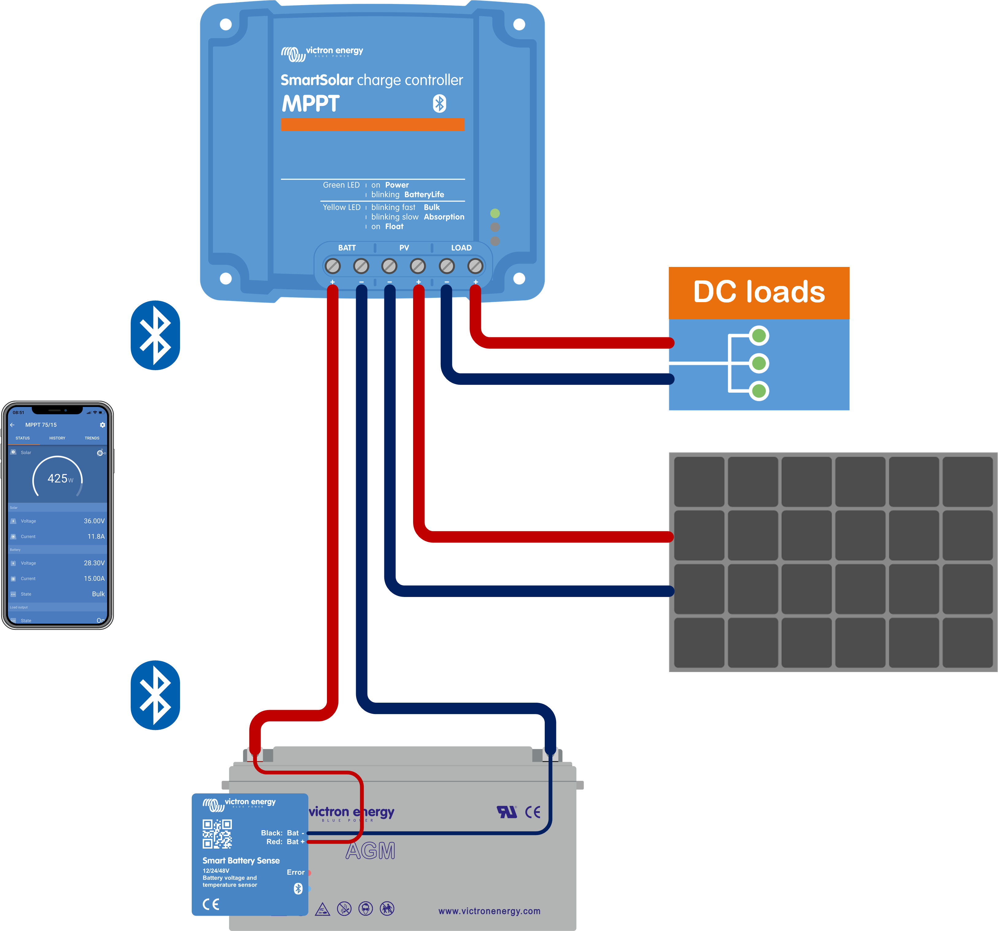 |
Example of a VE.Smart Network of a Smart Battery Sense and a solar charger.
3.11. Voltage sensing
An optional Smart Battery Sense or battery monitor measures the battery terminal voltage and sends this via Bluetooth using the VE.Smart network to the solar charger. If the battery voltage is less than the solar charge voltage, the solar charger will increase its charge voltage to compensate for voltage losses.
3.12. Remote on/off
A virtual remote on/off terminal can be created by using the (optional) VE.Direct non inverting remote on/off cable.
The functionality can be programmed using the VictronConnect App RX port function settings.
3.13. WireBox
The optional MPPT WireBox is a plastic cover that can be attached to the bottom of the solar charger. It covers the battery and solar terminals, preventing accidental or inquisitive contact with the battery and PV terminals. It provides an extra level of safety, and is particularly useful if the solar charger is installed in a general access area.
For more information and to find the right MPPT WireBox for your solar charger see the MPPT WireBox product page:
 |
Example of a solar charger with MPPT WireBox