 Add this page to your book
  Remove this page from your book
  Manage book (
 Help
Help This is an old revision of the document!
Table of Contents
Color Control GX manual
Note: this manual corresponds to Color Controls running the latest software. Internet-connected Color Controls will update to the latest version automatically. Check our blog posts for the latest firmware: http://www.victronenergy.com/blog/category/firmware/
1. Installation
1.1 Power
Power the Color Control GX (CCGX) on the Power IN V+ connector. It accepts 8 to 70 V DC. The CCGX will not power itself from the network connections. Use a 1A slow blow fuse.
VE.Bus BMS note: when the CCGX is used in an installation with a VE.Bus BMS, connect Power in V+ on the CCGX to the terminal called 'Load disconnect' on the VE.Bus BMS. And connect both negatives to a common Battery -.
Because the CCGX is connected to many different products, ensure that proper care is taken with isolation to prevent ground loops. In 99% of installations this will not be a problem.
- The VE.Bus ports are isolated
- The VE.Direct ports are isolated
- The VE.Can ports are isolated
- The USB ports are not isolated. Connecting a Wi-Fi Dongle or GPS Dongle does not create a problem, since it is not connected to another power supply. Even though there will be ground loop when you mount a separately powered USB hub, we did extensive testing and it did not cause any issues
- The Ethernet port is isolated, except for the shield: use unshielded UTP cables for the Ethernet network
Extending the number of USB ports by using a hub: there is a limit to the amount of power that the onboard USB port can provide. Especially when extending the number of ports, we recommend to always use powered USB hubs. And to minimize the chance of issues, do not use the lowest cost USB hub available.
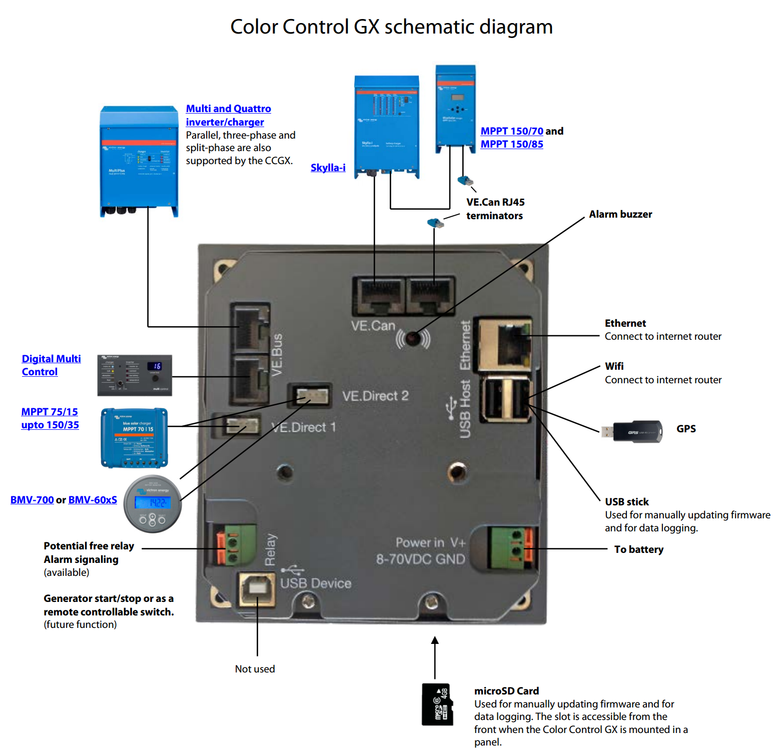
1.2 Connecting Victron products
1.2.1 Multis/Quattros/Inverters (VE.Bus products)
To keep this text short, Multis, Quattros and Inverters are referenced as VE.Bus products.
Note that it is not possible to use the Remote on/off (header on the VE.Bus control PCB) in combination with a Color Control GX. The jumper link needs to be in the header, as it is by default.
Single VE.Bus products
To connect a single VE.Bus product, connect it to one of the VE.Bus sockets on the back of the CCGX. Both sockets are identical, use either one. Use a standard RJ45 UTP cable, see our pricelist.
Parallel, split- and three-phase VE.Bus systems
To connect multiple VE.Bus products, configured as a parallel, split-phase or three phase VE.Bus system, connect either the first or the last VE.Bus product in the chain to the VE.Bus sockets on the back of the CCGX. Both sockets are identical, use either one. Use a standard RJ45 UTP cable, see our pricelist.
Hub-1 systems
In a hub-1 system, with one or more MPPT 150/70 or 150/85 solar chargers, the VE.Bus system needs to be connected to VE.Can using the VE.Bus to VE.Can interface (ASS030520105). In this case the VE.Bus system should not be connected directly to the VE.Bus ports on the back of the CCGX as well. Connecting the CCGX to the VE.Can network is sufficient: it will use the canbus to communicate to both the VE.Bus system as well as the solar chargers.
VE.Bus systems with Lithium batteries and a VE.Bus BMS
- Connect the CCGX to the socket labeled ‘MultiPlus/Quattro’, or to one of the Multis/Quattros in the system. Do not connect to the Remote panel socket on the VE.Bus BMS.
- The On/Off/Charger Only switch and the Current limiter options will be disabled in the CCGX menu. To remote control the Multi or Quattro when used with a VE.Bus BMS, add a Digital Multi Control to the system:
- Combining MultiPlus/Quattro with a VE.Bus BMS and a Digital Multi Control is possible. Connect the Digital Multi Control to the RJ-45 socket on the VE.Bus BMS labeled ‘Remote panel’.
- Power the Color Control GX through the VE.Bus BMS: connect Power in V+ on the Color Control GX to Load disconnect on the VE.Bus BMS. And connect both negatives to a common Battery -.
- The Color Control checks if a VE.Bus BMS or Digital Multi Control is present on power-up. Once the Color Control GX has seen one of these products, the On/Off/Charger Only switch and the Current limiter options will be disabled until you initiate a Redetect system, found in the Multi menu.
Combining the CCGX with a Digital Multi Control
It is possible to connect both a CCGX and a Digital Multi control to a VE.Bus system. The ability to switch the product On, Off or set it to Charger Only via the CCGX will be disabled. Same for the input current limit: when there is a Digital Multi Control in the system, the input current limit set at that control panel is leading, and changing it on the CCGX is not possible.
Connecting multiple VE.Bus systems to a single CCGX
Only one VE.Bus system can be connected to the VE.Bus ports on the back of the CCGX. To connect more than one system, use one VE.Bus to VE.Can interface (ASS030520105) for each additional system. Note that the VE.Can network needs to terminated and powered. For powering the VE.Can network, see Q17 in our data communication whitepaper. In case you were wondering: using an USB-MK2 to connect the second system is, unfortunately, not possible.
Note that the functionality will be limited: only one VE.Bus system will be made visible in the overviews. And the data on the VRM Portal will either be incorrect or will only contain data from one of the VE.Bus systems. There are no short term plans to improve this. The short term solution is to add a second Color Control GX.
1.2.2 BMV-700 series and MPPTs with a VE.Direct port
Up to two such products can be connected directly on the back of the CCGX, using a standard VE.Direct cable. There are two types of VE.Direct cable available:
- Straight VE.Direct cables, ASS030530xxx
- VE.Direct cables with an angled connector on one side, to minimize required depth behind a panel, ASS030531xxx
VE.Direct cables have a maximum length of 10 meters. It is not possible to extend them. If longer lengths are needed, use the VE.Direct to VE.Can interface. Note that this is only works for BMVs. Not for the MPPT solar chargers with a VE.Direct port. See next paragraph for more information on that VE.Can interface.
Connecting more than two VE.Direct products to a single CCGX
Option 1: use the VE.Direct to USB interface (ASS030530000). The CCGX has two USB ports. Use a USB-hub when more than two USB ports are needed.
Option 2: BMVs can also be connected using the VE.Direct to VE.Can interface (ASS030520400). MPPTs cannot be connected using this canbus interface since it does not (yet) translate the solar charger data into canbus messages. When using the VE.Direct to VE.Can interface, make sure that the VE.Can network is terminated, and also powered. For powering the VE.Can network, see Q17 in our data communication whitepaper.
Notes about older VE.Direct MPPTs
- The MPPTs need to run firmware version v1.09 or later. Contact Victron Service for update instructions and files if necessary.
- An MPPT 70/15 needs to be from year/week 1308 or later. Earlier 70/15s are not compatible with the CCGX, upgrading MPPT firmware will not help. To find the year/week number, look for the serial number which is printed on a label on the back. For example number HQ1309DER4F means 2013, week 09.
1.2.3 Skylla-i, Lynx Shunt VE.Can, Lynx Ion + Shunt and MPPTs with a VE.Can port
To connect a product with a VE.Can port, use a standard RJ45 UTP cable. See our pricelist, ASS030064xxx and ASS030065xxx. Do not forget to terminate the VE.Can network on both ends. A bag with two terminators is supplied with each VE.Can product. They are also available separately: ASS030700000.
Other notes:
- To work with the CCGX, an MPPT 150/70 needs run firmware v2.00 or newer.
- It is possible to combine a Skylla-i control panel with a CCGX.
- It is possible to combine a Ion Control panel with a CCGX.
- The Skylla-i, Lynx Shunt VE.Can, Lynx Ion + Shunt and the MPPTs with a VE.Can port all power the VE.Can network. It is therefore not necessary to separately power the VE.Can network. All the protocol converters, for example the VE.Bus to VE.Can interface, and the BMV to VE.Can interface, do not power the VE.Can network.
1.2.4 BMV-600 series
Use the VE.Direct to BMV-60xS cables, ASS0305322xx
1.2.5 DC Link box
Connect the DC Link box to a BMV-700, using the supplier RJ-12 cable. Then connect the BMV-700 to the CCGX, see above paragraph for instructions.
1.3 Measuring PV Inverter output
Measuring the output of a PV Inverter is recommended to provide the user with a total overview of both actual current power balance and energy distribution. Note that these measurements are only used for displaying purposes, and that they are not used, nor necessary, for the Hub-4 algorithms to operate.
There are multiple options to display the output of a PV Inverter on the Color Control GX:
- AC Current Sensor, wired to the analog inputs of a Multi or Quattro (lowest cost, least accurate). AC Current Sensor Manual.
- Fronius PV Inverters can be read out digitally via the local LAN. See the CCGX / Fronius manual.
- Wired HUB-4 Sensor, either wired to the CCGX, or connected wireless using our Zigbee to USB/RS485 interfaces. Instead of used for Hub-4 regulation, it can be configured to measure output of a PV Inverter. See the Hub-4 manual for wiring and configuration.
- Wireless AC sensors. See the Wireless AC Sensor manual.
1.4 Internet connectivity
Connect the CCGX to the internet to get all the advantages of the VRM Portal. The CCGX will send the data gathered from the connected products to the VRM portal (https://vrm.victronenergy.com/). Here it is possible to monitor your energy usage, view the current status of connected products, configure email alarms and download data in CSV and Excel formats.
Download the iOS or Android VRM App to monitor your system from your smartphone or tablet.
Besides sending data for remote monitoring, an active internet connection will also allow the CCGX to regularly check for a new firmware version, which will be (automatically) downloaded and installed. It is not necessary do this manually using a microSD or USB flash drive.
There are several ways to connect a CCGX to the internet:
- Run a network cable to its Ethernet LAN port
- Connect to Wi-Fi, using a USB Wi-Fi dongle plugged into the CCGX
- To a mobile (cellular) network, using a 3G or 4G router
- USB Tethering on a mobile phone
The four chapters below describe these options in detail.
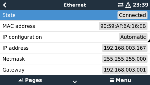
1.4.1 Ethernet LAN port
1.4.2 Wi-Fi USB dongle
Using a Wi-Fi dongle it is possible to connect to WEP, WPA and WPA2 secured networks. There are two supported USB Wi-Fi dongles. Both also available from stock at Victron Energy:
- CCGX WiFi module simple (Nano USB), small, low cost. Victron part number BPP900100200
- Startech USB300WN2X2D, slightly higher cost and also better reception. Victron part number: BPP900200100
Although other Wi-Fi dongles may work, others have not been tested and therefore we do not offer support for other dongles.
The Wi-Fi menu shows the available networks. When a network is selected, it is possible to fill in the password (if the password is not already known) to connect to the network. Setting up via WPS is not supported.
When the CCGX finds multiple Wi-Fi networks of which the password is known, the strongest network is selected automatically. When the signal of the connected network gets too small, it will automatically switch to stronger networks, when it knows the password of that network.
1.4.3 Mobile (cellular) network using a 3G or 4G router
To connect the CCGX to a mobile (cellular) network, use a 3G router. Connect the CCGX to that router with either a LAN cable or the router's Wi-Fi network. More information in this blogpost.
1.4.4 USB tethering on a mobile phone
Note that this is in the category: nice that it works, as long as it works, but don't rely on it. Enable USB tethering on your phone (See Google on how to do that for your particular make, model and operating system). It has been reported to work on:
- Samsung Galaxy S4
And reported not to work on:
- iPhone 5s with iOS 8.1.1
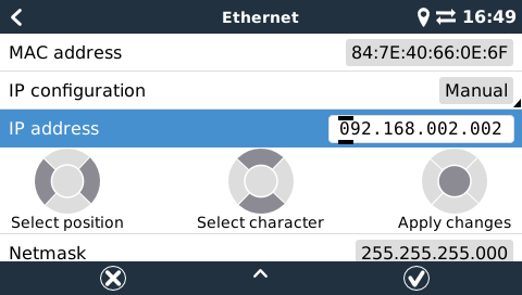
1.4.5 IP Configuration
For 99% of all installations, IP address configuration will not be necessary, since those networks support automatic IP configuration (DHCP). This is also the CCGX default setting. It is also possible to manually configure an IP address:
1.4.6 Connecting both Ethernet and Wi-Fi (failover)
It is possible to connect the CCGX to both Ethernet and Wi-Fi. In this case, the CCGX will try to determine which interface provides an active internet connection and then use that interface. When both have an active internet connection, the Ethernet connection is used. The CCGX will automatically check again for active internet connections when something changes on the interfaces.
1.4.7 Minimize internet traffic
In situations where internet traffic is expensive, for example a satellite uplink or with roaming GSM/cellular charges, you may want to minimize the internet traffic. The steps to take are:
- Disable auto-update
- Do not enable remote support
- Possibly set the Logging interval to a very low frequency. Note that state changes (charging → inverting, or bulk→float) and also alarms will cause extra messages to be sent
To find out how much traffic you need, in order to purchase the right plan, the best way is really to let the system run for a couple of days and monitor the internet RX and TX counters in your 3G or 4G router. Or even better, some mobile companies will report the data used via a website. Besides the above three points, the amount of data used is also very dependent on the system:
- More products connected will generate more data
- A state change (from inverter to charger for example) will trigger a data transmission, so a system with very frequent state changes will also tend to generate more data. This is especially true in certain Hub-1 and Hub-2 systems.
Note that CCGX versions prior to v1.18 would still check for software updates daily, even when auto-update was be switched off. This has been changed in v1.18: disabling auto-update also disables the check, saving a lot of data.
We recommend to set the mobile plan up in such a way that there are no surprises. Make sure to put a cap on data usage, or use pre-paid plans.
One customer has come up with an even more advanced plan. They had to, since they are using global roaming SIM Cards that start at EUR 0,20 cents per megabyte, but in the more interesting countries to visit they go up to several Euros per megabyte. His solution is using a VPN and he modified the IP routing table to route ALL traffic to and from the CCGX via his VPN. Using a firewall at the VPN server allows him to control traffic according to time, connection type, place and destinations. Note that this is really out of scope for Victron to support you with. If you need this, look for a Linux and networking expert that can help you.
1.4.8 More information about setting up an internet connection and VRM
1.5 Connecting a USB GPS
Use a GPS to track remote vehicles or boats and optionally get an alarm when they leave a designated area (geofencing). It is also possible to download a gps-tracks.kml file which can be opened with Navlink and Google Earth for example.
Use an off-the-shelf USB-GPS, Victron does not sell them. Plug it into one of the two USB sockets. After a while, which can take up to a few minutes, the CCGX will automatically recognize the GPS. The location is automatically sent to the VRM online portal, where it is used to show the position on the map.
The CCGX supports GPS modules that work with the NMEA0183 command-set, as almost all do. Both 4800 and 38400 baud. Tested for compatibility are:
- Globalsat BU353-W SiRF STAR III 4800 baud
- Globalsat ND100 SiRF STAR III 38400 baud
- Globalsat BU353S4 SiRF STAR IV 4800 baud
- Globalsat MR350 + BR305US SiRF STAR III 4800 baud
2 Configuration
2.1 Configurable parameters
After completing the installation and setting up the internet connection (when relevant), go through the menu from top to bottom to configure the CCGX:
| Item | Default | Description |
|---|---|---|
| General | ||
| Remote support | Off | Enable this to allow Victron engineers to access your system in case there is a problem. |
| Access level | User and installer | Set this to User only to prevent accidental and unwanted changes to the configuration. |
| Audible alarm | On | When there is an alarm on the CCGX or one of the connected products, the CCGX will beep, unless this setting is set to Off. |
| Demo mode | Off | Enable to On for shows or exhibitions to simulate a VE.Bus system and some other products. |
| Update firmware | ||
| Auto update | On | We recommend to leave this enabled. A reason to disable it can be to completely eliminate the risk of a firmware update causing problems. For example on a very remote and difficult to access installation. Another reason to disable it is to reduce internet traffic usage. |
| Update to | Latest release | Leave this set to the default setting, 'Latest release', unless you want to participate in test versions. Note that we do not recommend setting Color Controls which are installed in customer systems to anything other than 'Latest release'. |
| Date & time | ||
| Select the correct time zone. | ||
| Remote console | ||
| Enable password check | Enable and set password authentication to access to the remote console. | |
| Disable password check | Disable password to access the remote console. | |
| Enable on VRM | No | Enable on VRM allows connection to the CCGX anywhere through the VRM portal. |
| Enable on LAN | No | Enable direct connection to the CCGX typing it's IP address on a web browser. Enable it only on trusted networks. |
| System setup | ||
| AC input 1 | Generator | Select Generator or Grid. Soon we will also allow to set this to Shore power instead of grid. |
| AC input 2 | Grid | Same choices as above. |
| Battery monitor | Automatic | Select the SOC source. Useful for systems with multiple BMVs. More details. If using the VRM portal, ensure the VRM Main Battery source setting under Settings –> General on the VRM site matches the CCGX SOC source. |
| Synchronize VE.Bus SOC with battery | No | Continuously updates the VE.Bus SO with the one provided by the selected battery monitor. |
| Has DC system | No | Enable this for boats, vehicles and other installations with DC loads and chargers other than the Multi and MPPT chargers. Not applicable for most off-grid installations. The difference between the DC current measured by the Multi and by the BMV will be attributed to a 'DC system'. It can be an alternator, pumps, DC fridge, etcetera. Note that the value shown will always be an approximation.(in order to achieve this and make changes in the system setup page, you have to change the access level to user&installer, the initial password is “zzz”) |
| Display & language | ||
| Brightness | Configure the brightness between 0 and 100% | |
| Display off time | Set between 10 seconds and 30 minutes, or never | |
| Language | English | Choose between English, Dutch, Chinese, German, Spanish, French, Italian, Swedish, Turkish and Arabic. |
| VRM online portal | ||
| Log to | Internet | Choose between no logging at all, logging via the internet directly to the VRM Portal, and logging to a microSD card or USB flash drive. See chapter below for more information. |
| Log interval | 15 minutes | Set to anything between 1 minute and 1 day. Choose longer times on systems with an unreliable connection. Note that this setting does not affect reporting problems and state changes (bulk → absorption) to the VRM Portal: such events will initiate an immediate transmission of all parameters. |
| Wireless AC Sensors | ||
| Select the position for each AC sensor (PV Inverter on AC-input 1, 2 or on AC-output). More information about the Wireless AC sensors. | ||
| Wired AC Sensors | ||
| Configure the Wired AC Sensor, used for one of three things: measure the output of a PV Inverter, measure and regulate a Hub-4 system measure the output of an AC Generator. |
||
| Ethernet | ||
| Select the configuration type (DHCP vs. manual configuration) and IP settings. | ||
| Wi-Fi | ||
| Manage wireless networks and IP settings. | ||
| GPS | ||
| Format | Select the format in which to show the Latitude and Longitude. | |
| Speed unit | km/h | Choose between km/h, meters per second, miles per hour or knots. |
| Generator start/stop | ||
| Configure generator autostart settings and conditions. generator_start_stop | ||
| Relay | ||
| Polarity | Normally open | Select the polarity of the relay on the back of the CCGX. Normally open or normally closed. Note that setting it to normally closed increases the CCGX power draw. |
| Services | ||
| ModbusTCP | Off | This setting enables the ModbusTCP service. More information about ModbusTCP in this document: http://www.victronenergy.com/upload/documents/Whitepaper-Data-communication-with-Victron-Energy-products_EN.pdf |
| VRM two-way communication | No | Enable remote configuration and firmware updates. VE Power Setup manual |
When using a VE.Bus system, it is possible to configure the severity of problems on the VE.Bus system that should cause a notification to show up on the CCGX (and make it beep):
- Disabled: the CCGX should never beep and show a notification
- Alarm only: the CCGX should only beep and a show a notification when the VE.Bus system switched off in an alarm condition.
- Enabled (default): the CCGX should beep and show a notification
When all done, don't forget to change the access level to user when required.
Click the thumbnail below to see the complete menu-tree:

2.2 Logging data for the VRM portal
The CCGX can be used in combination with the Victron Remote Management (VRM) portal: The CCGX monitors all products connected to it and the VRM portal makes the statistics easily accessible. There are two options to get the sampled data from the CCGX to the VRM portal:
- 'Internet'
- 'microSD or USB storage'.
The method, together with the logging interval, can be set in the 'VRM online portal' menu.
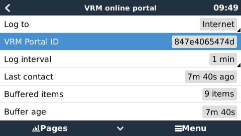
2.2.1 Option 1 - Log to Internet
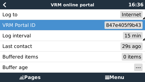
Set the 'Log to' setting to 'Internet' to let the CCGX send data directly to the VRM portal via the internet. When the VRM portal cannot be reached, the data is placed in a backlog buffer. The CCGX will regularly try to connect to the VRM portal, to upload the backlog buffer data. The maximum age of the data in this backlog buffer is 48 hours. Any data older than 48 hours is discarded. The backlog buffer is stored in non-volatile memory, so the data will not be lost if the CCGX loses power and is rebooted.
Note that once there is data in the backlog buffer, the oldest data will be uploaded first. And if the internet connection is too intermittent or too slow, it might result in a continuous message on VRM: 'Last connection two days ago'.
2.2.2 Option 2 - Log to microSD or USB storage
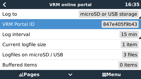
When the CCGX is not connected to the internet, 'Log to' should be set to 'microSD or USB storage'. The CCGX will store the data on a microSD or USB flash drive inserted into the CCGX. The data is stored per month in vrmbacklog*.sqlite3 files. These monthly files can be manually uploaded to the VRM website by removing the microSD card or USB stick from the CCGX, inserting them into your computer or laptop, and uploading them using the CCGX Data Upload widget on the VRM Portal:
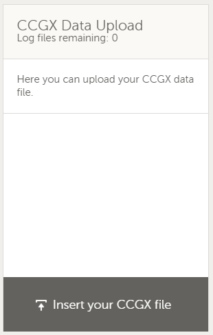
Note that this widget needs to be enabled in Settings → Advanced tab setup.
If there is (temporarily) no microSD card or USB flash drive inserted, the data is placed in a non volatile backlog buffer for a maximum of 48 hours. As soon as the microSD or USB flash drive is connected again, the CCGX will move the data from the backlog buffer, to the inserted storage. This means that the microSD card or USB flash drive can be temporarily removed without losing data. The backlog buffer is stored in non-volatile memory, so the data will not be lost if the CCGX loses power and is rebooted.
If both a microSD card and a USB flash drive are connected to the CCGX, then data is logged to the one that was inserted first. If one is removed, the CCGX will not try to write to the other, but will create a local backlog buffer until a new storage medium is inserted and then use that storage medium.
The microSD card or USB flash drive must be formatted as FAT12, FAT16 or FAT32 file system and not exFAT or NTFS. SD and SDHC type microSD cards which are less than or equal to 32 GB are sold containing FAT12, FAT16 or FAT32. This means they can be used without a problem, unless they are subsequently formatted to a different and non acceptable file system. SDXC type microSD cards which are mostly greater than 32 GB are sold with exFAT, and therefore cannot be used with the CCGX.
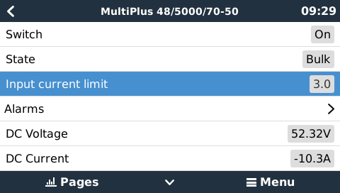
2.3 Configuring Multi and Quattro input current limiter setting
This chapter explains how to enable or disable user control of the input current limiter setting, as available here in the menu:
The limit as set by the user in the CCGX will be applied to all inputs where 'Overruled by remote', configured with VEConfigure, is enabled:
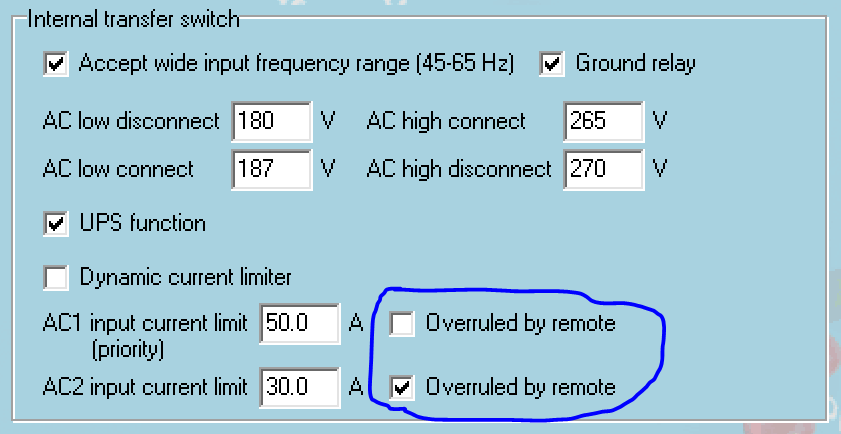
As an example a boat with two inputs, and a Quattro:
- genset capable of delivering 50A, connected to input 1;
- shore power connected to input 2, actual available power depends on rating of the available connection in the harbour.
In that case, configure the system exactly as in above VEConfigure screenshot. Input 1 has priority over input 2, therefore the system will automatically connect to the genset whenever it is running. The fixed input current limit of 50A will be applied. And when the genset is not available, and mains is available on input 2, the Quattro will use the input current limit as configured in the CCGX.
Two more examples, if you disable overrule by remote For both of them, setting a current limit in the CCGX will have no effect. And the opposite: if you enable 'Overruled by remote' for both inputs, the current limit set in the CCGX will be applied to both inputs.
Note that it is not possible to control the input current limit in certain installations. In these cases, the CCGX menu will not allow changing the setting:
- Installations with a VE.Bus BMS
- Installations with a Digital Multi Control (or its predecessors)
2.4 Select SOC source from the GUI to display on the main Overview screen
(Settings → System Setup → Battery monitor)
In the image below you can see a range of selectable choices for the SOC values that will be shown in the main Overview screen. Choose the source you want to see on the main Overview screen of your CCGX.

In the example image above we have chosen the Automatic setting. When automatic is selected, the System setup screen for this example will then report as shown in the image below.

The 'Automatic' function uses the following logic:
- First try to use a battery service (BMV or Lynx Shunt VE.Can).
- If there is more than one battery service, just use a random one.
- If no battery service is available, check there are no solar chargers and no normal chargers.
- If there are none present, assume that there are no other DC chargers or loads, and that it is therefore safe to use the VE.Bus SOC (more info on BMV vs VE.Bus SOC).
The 'No battery monitor' choice:
Use the 'No battery monitor' choice in systems where there is only a Multi connected to the CCGX, and no battery monitor, even though that system does have other DC loads or other chargers connected to the same battery, making the SOC from the Multi incorrect.
See also this CCGX FAQ page on whether a BMV is necessary in a system or not.
3 More information resources
DISQUS Comments
~~DISQUS~~