 Add this page to your book
  Remove this page from your book
  Manage book (
 Help
Help Table of Contents
Wireless AC Sensor manual
(discontinued product)
Introduction
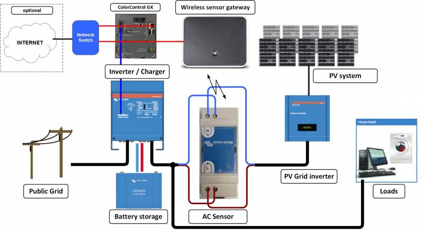
The Wireless AC sensors are used to measure and calculate PV Inverter current (A), voltage (V), power (W) and energy (kWh), and show it on a GX device and the VRM Portal. An installation will have one gateway per system and one sensor per phase. The gateway connects to the GX device via Ethernet, and is the DECT hub for the sensors. Multiple sensors connect to 1 gateway.
Note that it is not possible to use multiple sensors on the same position (AC-Out, AC-In 1, etcetera) in a system. The GX device will in such case only show the value of the last-read sensor.
Three phase
For measuring a three phase system, we recommend to use this meter instead. Using three single phase meters does not provide true three-phase metering and measurements.
Required hardware
- TIM000100100 - Wireless AC sensor 25A (one for each phase)
- TIM000100000 - Wireless Sensor gateway (one for every system)
Included with the gateway:
- RJ45 cable 30cm
- AC adapter
 Note that instead of powering the Wireless Sensor gateway with the AC adapter, it is also possible to power it from one of the USB ports in the GX device. Purchase a separate male Micro-USB to male USB cable, not available from Victron Energy. Note that, due to GX device-USB port power limitations, this cannot be combined with a USB-GPS, USB-WiFi using a non powered USB hub.
Installation
Installing the gateway
- Disconnect the AC power
- Connect the gateway to the Ethernet/LAN network using the supplied RJ45 cable.
- Connect the AC power adapter or the USB cable from the GX device to the gateway
Installing the sensor(s)
For each phase, connect the AC sensor according to the schematic below. Neutral on top side. Line on bottom side. Make sure the direction of the current is correct.
Gateway and sensor pairing
After powering the sensor for the first time, it needs to be paired with the gateway. The led on the sensor will be blinking red, to indicate that it is not yet paired to a gateway.
If it is not blinking red, but both the green and the red LED are on, it needs to be unpaired first: press and hold the little reset button in the sensor. As soon as you press the button the LED will turn green. Hold the button until the LED starts blinking red.
To let the gateway search for and pair with free sensors, press the button on the gateway for 5 seconds. The led on the gateway will start blinking red. First slow then both leds (gateway and sensor) will start blinking red fast. If sensor is found the led will shortly blink orange.
The discovery will take anywhere between 30 seconds and 12 minutes. The 12 minutes can be because of a software update.
When the update process is completed then the sensor LED will be off, and the gateway LED will be green with short intermittent blips of red.
Gateway LED
| LED | Meaning |
|---|---|
| Blinking red | Searching for sensors |
| Green with short blips of red | Working OK |
Sensor LED
| LED | Meaning |
|---|---|
| Blinking red | Not yet paired to a gateway |
| Both green and red on (no blinking) | Cannot find the gateway. Only shows for a few seconds, after that the led will turn off |
| Alternating red/green | Selected in the GX device menu, useful for identification |
| Green on (no blinking) | Gateway found, connecting. This will show only for a few seconds |
| Off | Working OK, connected to the gateway, cannot find gateway or not powered |
Configuration on the GX device
Wireless AC sensor menu
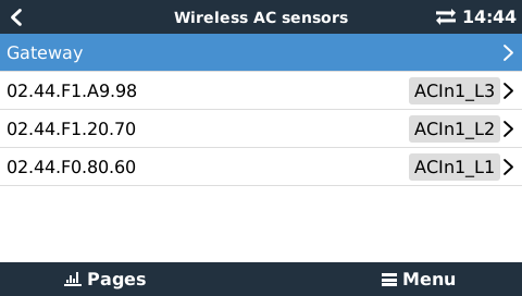
To configure the gateway and sensor go to the Wireless AC sensor menu
Settings → Wireless AC Sensors
If the gateway is connect to the network it will be shown in the list. If one or more AC sensors are connected these will also show in the list. When connected for the first time only the ID number will be shown and no location. This needs to be selected for the sensor to work properly.
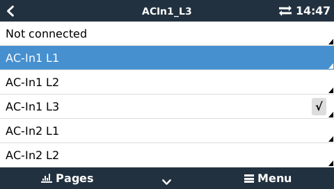
Select a sensor to assign a location to it. For example AC-In1_L3.
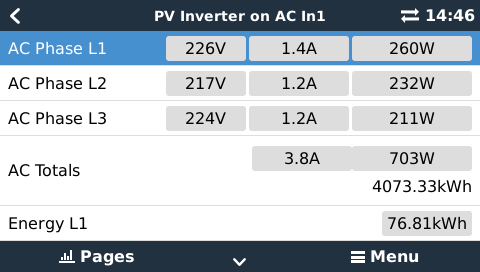
Sensor readout
When all the sensor are configured the measured values can be seen. Go to the Device List and select PV Inverter on AC In1 for example.
Specifications
| Rated voltage | 230 | V AC |
| Operating Voltage | 220-240 | V AC |
| Frequency | 50 | HZ |
| Maximum Current | 25 | A |
| Measurement precision | +/- 2% | |
| Ambient temperature | -25 ~ +35 | oC |
| Storage temperature | -25 ~ +70 | oC |
| Relative humidity | 0 - 95 | % |
DISQUS
~~DISQUS~~