17. Digital Inputs
The Venus GX digital inputs are shown in the Overview of connections.
All digital input channels are accessible via the RJ12 socket on the side. This is available for self-wiring by the user/installer.
17.1. Wiring details
The digital inputs are non-isolated and operate at 3.3 V logic level, with a maximum input tolerance of 5 V.Each input includes an internal 10 kΩ pull-up resistor to 3.3 V.
Recommended wiring: Use a potential-free relay contact or an open collector/optocoupler output.
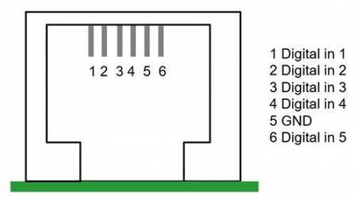 |
RJ12 pinout | Input |
|---|---|
pin1 | input1 |
pin2 | input2 |
pin3 | input3 |
pin4 | input4 |
pin5 | gnd |
pin6 | input5 |
17.2. Configuration
Each digital input can be configured as one of several predefined sensor types, with the option to set them up as alarms.
The possible configurable functions are:
Function | States |
|---|---|
Pulse meter | N/A |
Door alarm | Open/Closed |
Bilge pump | On/Off |
Bilge alarm | Ok/Alarm |
Burglar alarm | Ok/Alarm |
Smoke alarm | Ok/Alarm |
Fire alarm | Ok/Alarm |
CO2 alarm | Ok/Alarm |
Generator | Running/Stopped |
The function of each input can be configured in the Remote Console under Settings → Integrations → Digital I/O. Once the input is configured for its intended purpose, it will show up in the Device list. |    |
Other parameters related to that function can be configured by entering the device menu from the Device list and selecting Setup. For sensors and alarms, you can decide whether the input should be treated as an alarm condition, whether the labels should be inverted, and whether the logical levels should be inverted.
For GX devices whose digital inputs can be used as pulse meters (Cerbo GX MKII, Ekrano GX and Venus GX), you can configure the unit and multiplier (representing the volume per pulse) and reset the counter as needed. |    |
17.3. Read-out of digital inputs via Modbus TCP
The values/states of the digital inputs can be read via Modbus TCP.
For full details, refer to the following resources available on our website:
Modbus-TCP Register List (downloadable document)