2. Theory
You will get the most out of this book if you have knowledge of basic electrical theory. This will help you to understand the underlying factors that determine wiring thickness and fuse ratings. You might already have this basic understanding and can perhaps skip this chapter, but we highly recommend that you read this chapter. |
2.1. Ohm's Law
Ohm’s law is the most important law of an electric circuit. It is the basis of almost all electrical calculations. It allows you to calculate the current that runs through a cable (or a fuse) at different voltages. Knowing how much current runs through a cable is essential knowledge to be able to choose the correct cable for your system. But first, some basic knowledge about electricity is needed. |
What is electricity: Electricity is the movement of electrons in a material, called a conductor. This movement creates an electric current. This current is measured in “Ampere” (amps for short) and the symbol is the letter A. The force required to make the electrons flow is called voltage (or potential). It is measured in "Volt" and the symbol is the letter V (In Europe also referred to as U). When an electrical current passes through a material, it meets a certain resistance. This resistance is measured in Ohm. The symbol is Ω.  |
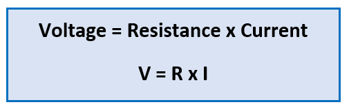
How do voltage, current and resistance relate to each other:
|
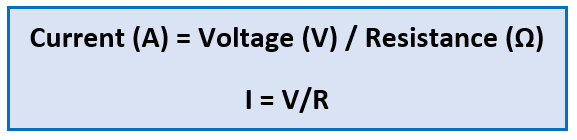
Ohm's law: You can say that the resistance of a conductor determines how much current runs through a material at a given voltage. This can be represented in a formula. The formula is called Ohm’s Law: | |
|
2.2. Power
Ohm’s law describes the relationship between resistance, current and voltage. But there is one more electrical unit that can be derived from Ohm’s law, and this is power. Power is an expression of how much work an electric current can do. It is measured in Watts, and the symbol is P. It can be calculated using the following formula: 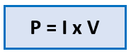 |
From Ohm’s law, other formulas can be derived as well. All possible formulas are listed in the below image. Please note that there are two symbols in use in the world that represent voltage. These are U or V. 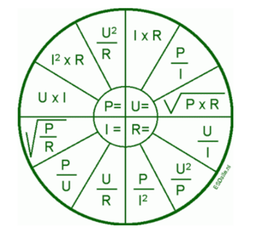 |
Some of these formulas are very useful when calculating the current in a cable. One often used formula is: 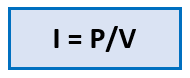 This formula can calculate how much current runs through a cable when the voltage and the power are known. |
An example of how this formula can be used: | ||
Question:
Answer:
|
| |
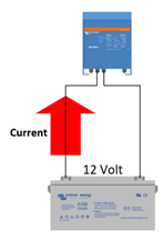
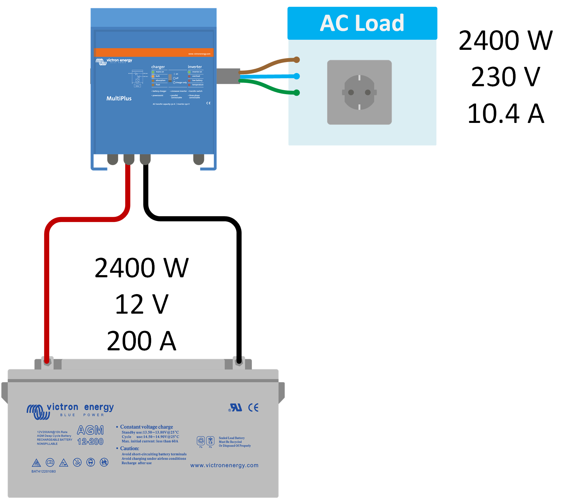
The benefits of using power instead of current in calculations: A big advantage of using power in calculations or for measurements is that power is independent of voltage. This is useful in systems where multiple voltages exist. An example of this would be a system with a DC battery, AC power and perhaps a solar panel with a different DC voltage than the battery. Power remains the same across the different voltages. For example, if you run an AC load of 2400W via an inverter from a 12V battery, it will also take 2400W from the battery (ignoring the inverter inefficiencies). |
|
2.3. Conductivity and resistance
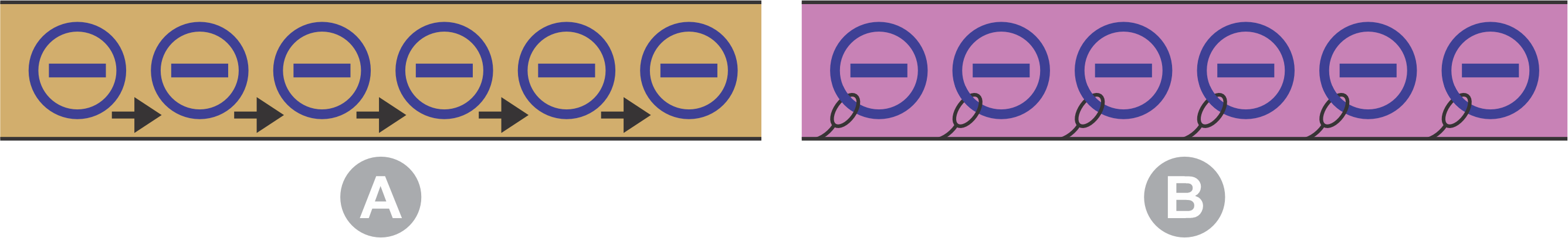
Some materials conduct electricity better than other materials. Materials with a low resistance conduct electricity well, and materials with a high resistance conduct electricity poorly or not at all. Metals have a low resistance, and they conduct electricity well. These materials are called conductors. This is the reason they are used as the core in electrical cables. Plastic or ceramics have a very high resistance; they do not conduct electricity at all. They are called insulators. This is why non-conductive materials, like plastic or rubber, are used on the outside of cables. You will not get an electrical shock when you touch the cable because electricity cannot travel through this material. Insulators are also used to prevent a short circuit should two cables touch each other.
A: In a conductor, the electrons can move. B: In an insulator, the electrons cannot move or move very slowly. |
Each material has its own specific resistance. It is measured in Ohm meters (Ω.m). and the symbol is ρ (rho). The conductivity of a material is inversely proportional to its resistance. It is represented by this formula: σ = 1/ρ. it is measured in Siemens per meter (S/m) meter, and its symbol is σ (sigma). The table below lists various conductive materials, their electrical conductivity, and specific resistance. As shown, copper conducts electricity well and has a low resistance. As shown, copper is an excellent conductor with low resistance, which is why it is commonly used in electrical cables. In contrast, titanium has poor electrical conductivity and a higher specific resistance, making it less suitable as an electrical conductor. |
Material | Electrical conductivity (10.E6 Siemens/m) | Electrical resistivity (10.E-8 Ohm.m) |
|---|---|---|
Silver | 62.1 | 1.6 |
Copper | 58.5 | 1.7 |
Gold | 44.2 | 2.3 |
Aluminium | 36.9 | 2.7 |
Molybdenum | 18.7 | 5.3 |
Zinc | 16.6 | 6.0 |
Lithium | 10.8 | 9.3 |
Brass | 15.9 | 6.3 |
Nickel | 14.3 | 7.0 |
Iron | 10.1 | 9.9 |
Palladium | 9.5 | 10.5 |
Platinum | 9.3 | 10.8 |
Tungsten | 8.9 | 11.2 |
Tin | 8.7 | 11.5 |
Bronze | 7.4 | 13.5 |
Carbon steel | 5.9 | 16.9 |
Lead | 4.7 | 21.3 |
Titanium | 2.4 | 41.7 |
Two more factors determine cable resistance. These are the length and the thickness of the conductor (cable): These factors relate in the following way:
|
The resistance of a length of cable can be calculated by the following formula:
|
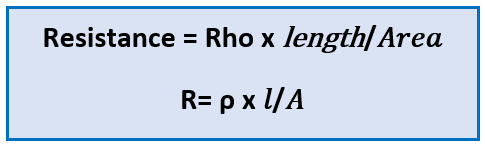
As in the above formula, three factors determine cable resistance. Namely:
|
It is important to know the resistance of a cable because when a current passes through a cable, the cable resistance is responsible for these two effects:
If the current increases, these effects will worsen. An increased current will increase the voltage drop and the cable will heat up more. |
An example of how to calculate the resistance of a cable: Question:
Given:
Answer:
|
The effect of cable length: Let’s use the previous example and calculate the resistance for a 5-meter cable. The result will be that the resistance is 5.3mΩ. If you increase the cable length, the resistance will increase. |
The effect of cable thickness: Let’s take the original example and calculate the resistance for a cable with a cross-section of 2.5mm². The result will be that the resistance is 10.2mΩ. If you make the cable thinner, the resistance will increase. |
Conclusion: Both cable thickness and cable length have a big impact on cable resistance. |
2.4. Electrical insulation
Electrical insulators are used to prevent the flow of electrical current from one part of an electrical circuit to another and to protect people and equipment from electric shock. As we saw in the table in the previous chapter, if a material does not conduct electricity well, it is called an insulator. Examples of electrical insulators include rubber, plastic, glass, ceramics, and air. These materials are used in various electrical applications, such as insulation for wires, insulators for electrical equipment, and coatings for electrical components. Electrical insulators play a critical role in ensuring the safe and efficient operation of electrical systems and in preventing electrical hazards. As a rule of thumb, the higher the voltage, the thicker or better the insulation needs to be. This is why, for example, special cables are required to and from a high-voltage solar array. Insulated cables and electrical tools are rated for a specific maximum voltage. Ensure that this voltage rating matches your application. |
2.5. Connection resistance
Resistance in an electrical installation is not solely determined by the resistance of the cable, as the resistance of the electrical connections also contributes to the total resistance. How is connection resistance created: Whenever a connection is made between a cable and an appliance or between a cable and a cable terminal the resistance of the circuit increases. The degree of resistance is influenced by the quality of the connection and the size of the connecting area.
|
How to limit connection resistances:
|
|
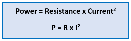
Be aware that resistance will also create heat: A poor connection with high resistance will generate excessive heat. The relationship between power, current, and resistance is described by the formula P = I²R. In extra-low voltage DC, even a small amount of resistance can result in a dangerous level of heat that can cause equipment and cables to become damaged, or even cause a fire in severe cases. |
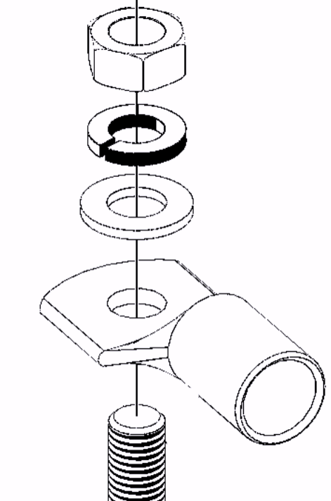
2.6. Torque
As described in the previous chapter, tight electrical connections are important, as loose connections will lead to resistance, heat, and potential corrosion due to arcing. However, be aware not to over-tighten these connections, as damage to the connector fastener might occur. Electrical connection fasteners, screws or bolts are often made of tin-plated brass. It is a common misconception to assume that these fasteners are made of stainless steel with over-tightening and damage to the fastener as a result. Always use a torque wrench (or torque screwdriver), so you know the bolt or screw is tightened correctly. Note that our products have metric connection bolts. Commonly used threads are M4, M5, M6, M8, and M10. The recommended torque values in our documentation are listed in N.m (Newton meter). | |
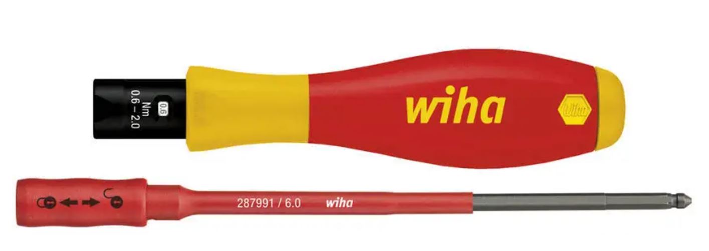 Insulated torque screwdriver. |  Insulated torque wrench. |
How to correctly use a torque wrench To use a torque wrench, follow these steps:
NoticeNote that it is important to follow the manufacturer's instructions and guidelines when using a torque wrench to ensure accuracy and prevent damage to the tool or the equipment being worked on. |
The maximum torque for brass bolts can vary based on factors such as the type of brass, the size and length of the bolt, and the intended use. Generally, the maximum torque for brass bolts is lower than for steel bolts of the same size. The product manual normally states the maximum torque moment for the electrical connections. But if this information is missing, use the below table for brass bolts, nuts or screws. Maximum torque values for brass (H62) fasteners:
NoticeNote that these are rough estimates and may vary based on the specific application, so it is important to consult the product manual or engineering guidelines to determine the appropriate torque value. Over-torquing a bolt can lead to damage or failure of the bolt or the components being fastened. |
2.7. Current, cable resistance and voltage drop
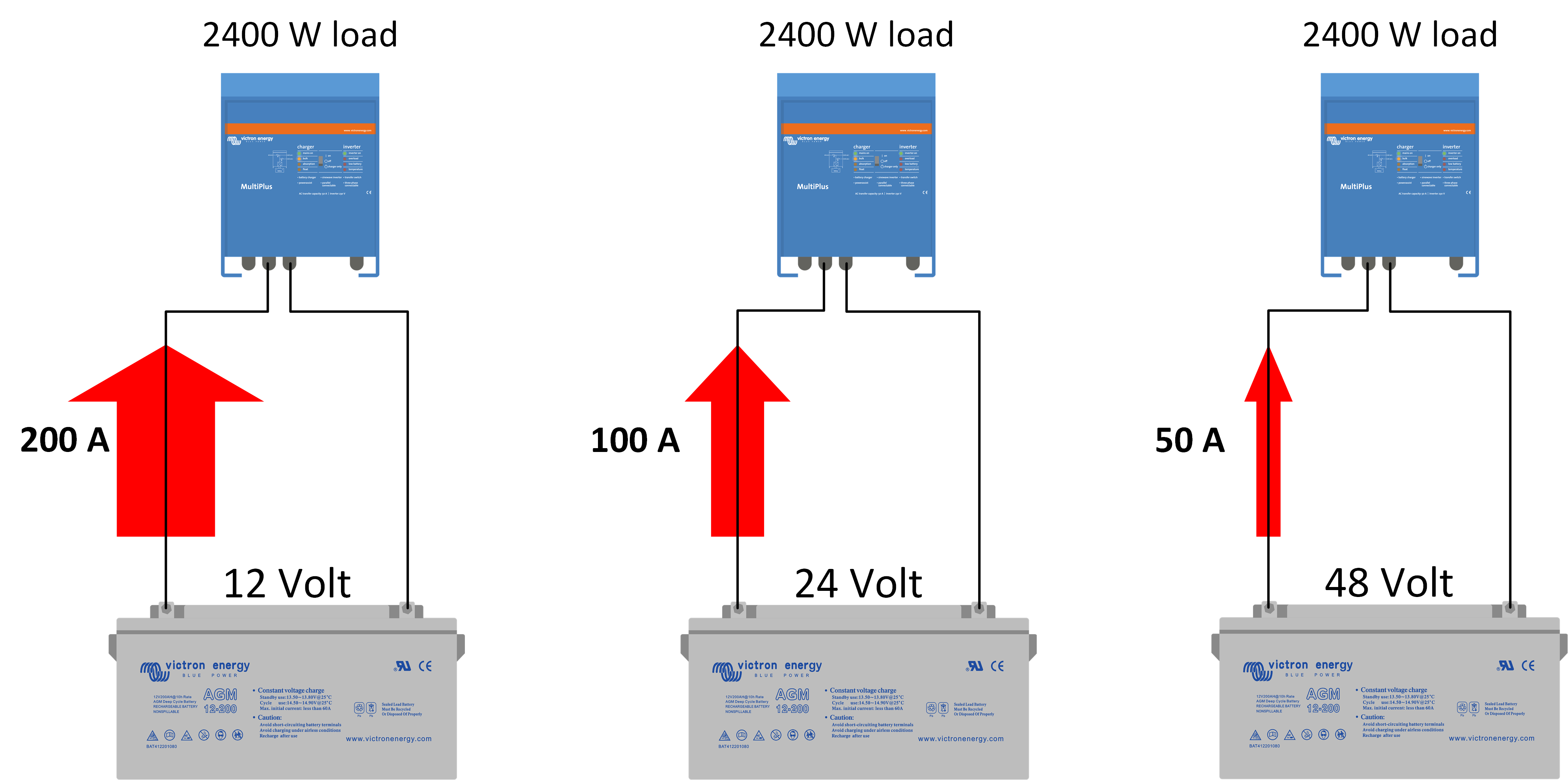
A low voltage results in a high current: As already explained, the current that flows through an electrical circuit for a fixed load is different for a variety of circuit voltages. The higher the voltage, the lower the current will be. Below is an overview of the amount of current that flows in three different circuits where the load is the same, but the battery voltage in each circuit is different:
|
Cable resistance creates a voltage drop over the cable: Also, as explained already, a cable has a certain amount of resistance. The cable is part of the electrical circuit and can be treated as a resistor. When current flows through a resistor, the resistor heats up. The same happens in a cable; when current flows through a cable, the cable heats up and, power is lost in the form of heat. These losses are called cable losses. The lost power can be calculated with the following formula:
Another effect of cable loss is that a voltage drop will be created over the length of the cable. The voltage drop can be calculated with the following formula:
|
The 1st and 2nd law of Kirchhoff: To be able to calculate the effect of a cable voltage drop, you will need to know two more electric laws, namely the first and second law of Kirchhoff: | |
Kirchhoff's current law (1st law): The current flowing into a junction must be equal to the current flowing out of it. An example of this is a parallel circuit. The voltage over each resistor is the same while the sum of current flowing through each resistor equals the overall current. | 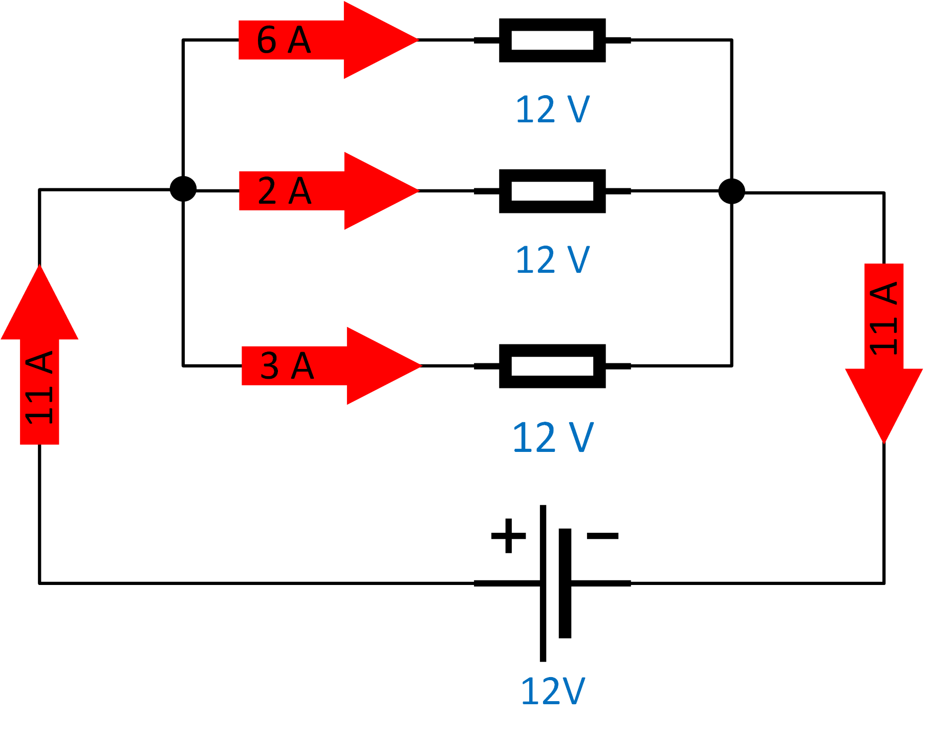 |
Kirchhoff's voltage law (2nd law): The sum of all voltages around any closed loop in a circuit must equal zero. Here the exact opposite is the case. In a series circuit, the current through each resistor is the same, while the sum of the voltages over each resistor equals the overall voltage. | 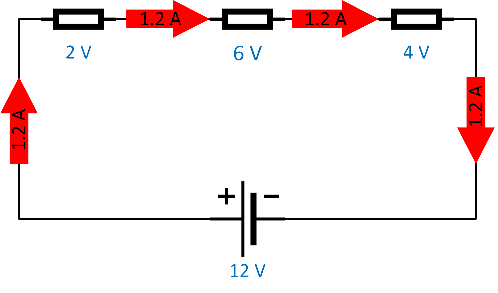 |
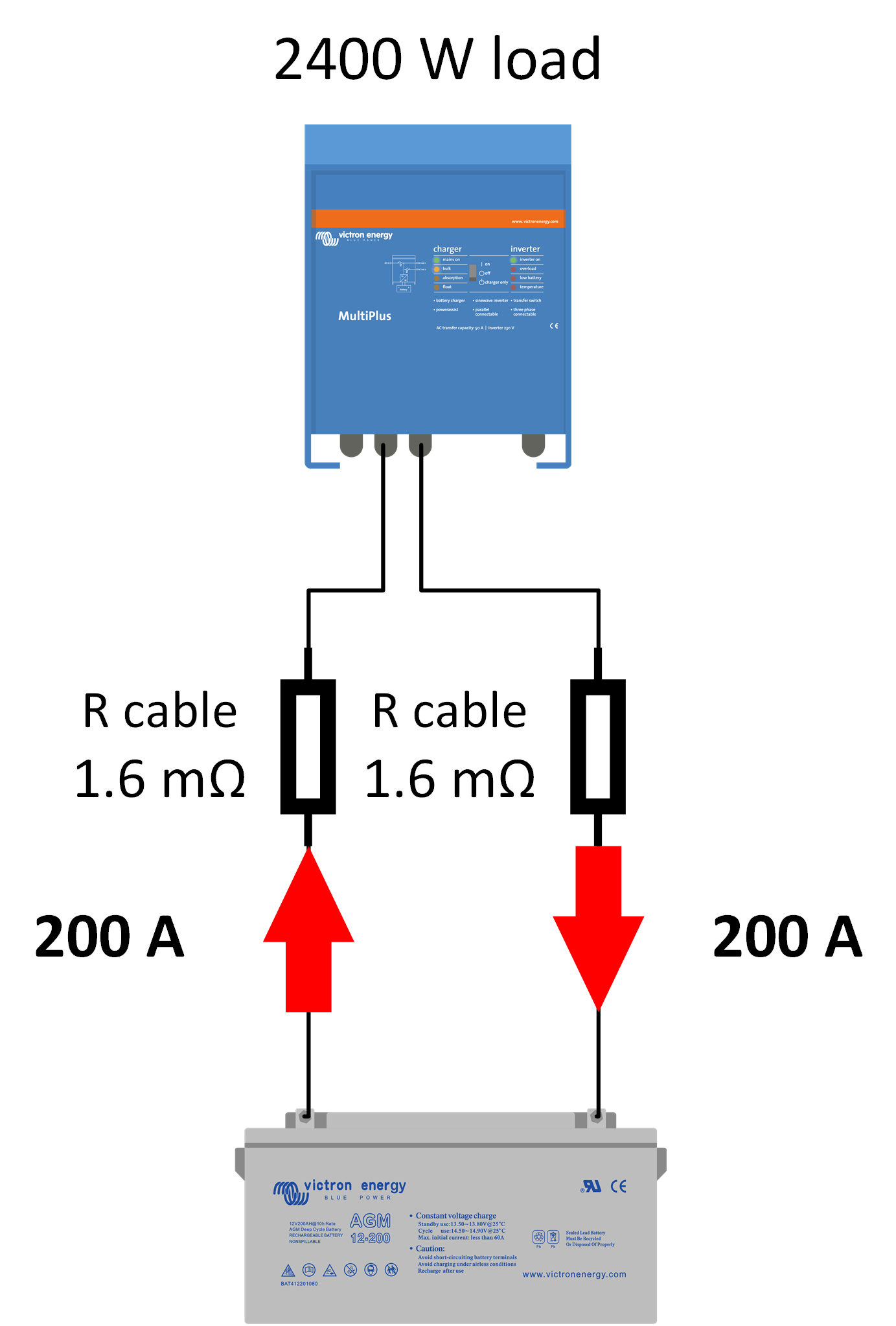
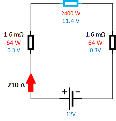
Voltage drop calculation example: Now, let’s use a real-world example of an inverter that is connected to a 12V battery and calculate the cable losses. In the circuit diagram on the right, you find a 2400W inverter connected to a 12V battery using two 1.5-meter-long, 16 mm2 cables. As we calculated earlier, each cable has a resistance of 1.6mΩ. Knowing this, we can now calculate the voltage drop over one cable:
|
| |
The power of the inverter is constant in this circuit. So, when the voltage to the inverter drops, the current will increase. Remember I = P/V. The battery will now deliver more current to compensate for the losses. This means, in the earlier example, that the current will increase to 210A. This makes the system inefficient because we now have lost 5% (0.64/12) of the total energy. This lost energy has been turned into heat. |
|
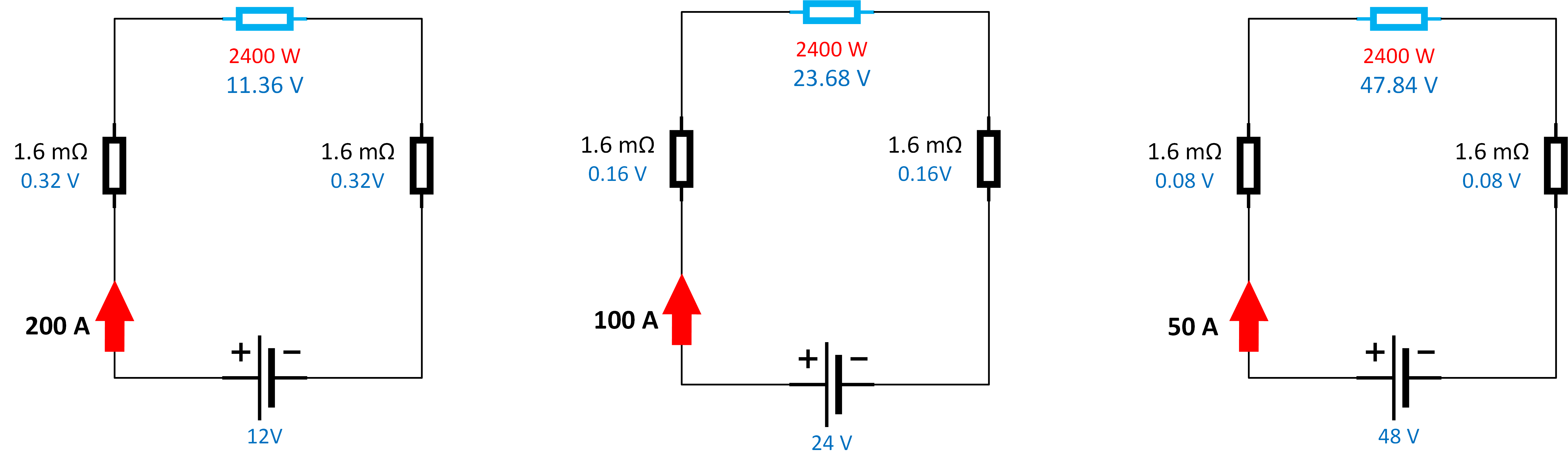
How to reduce voltage drop: It is important to keep the voltage drop as low as possible. The obvious way to do that is to increase the thickness of the cable or to keep the cable length as short as possible. But there is something else you can do. This is to increase the voltage of the electric circuit. The cable voltage drop varies for different battery (system) voltages. Generally speaking, the higher the voltage of the circuit, the lower the voltage drop will be. Example: If we look at the same 2400W load, but now the system voltage is 24 or 48V:
 |
How much voltage drop is allowed? This leads to the next question; how much voltage drop is allowed? The opinions vary somewhat, but we advise aiming for a voltage drop no bigger than 2.5%. This is indicated in the below table for the different voltages:
|
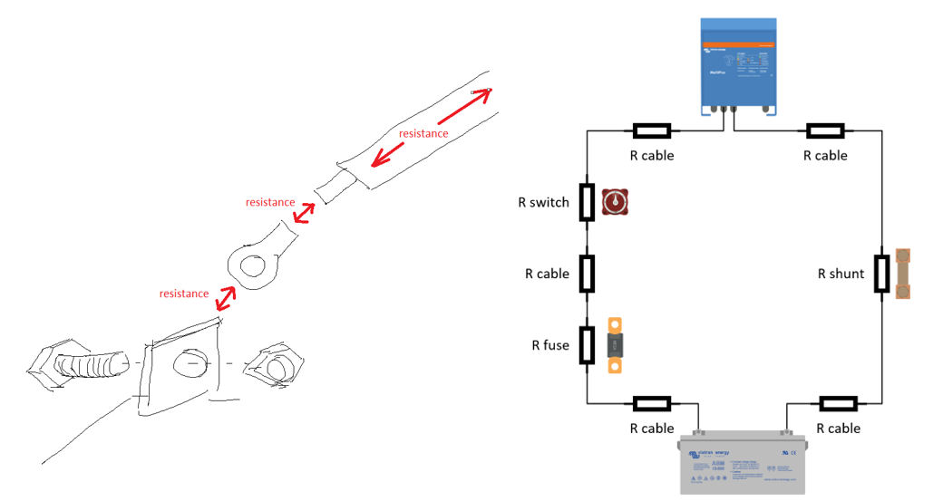
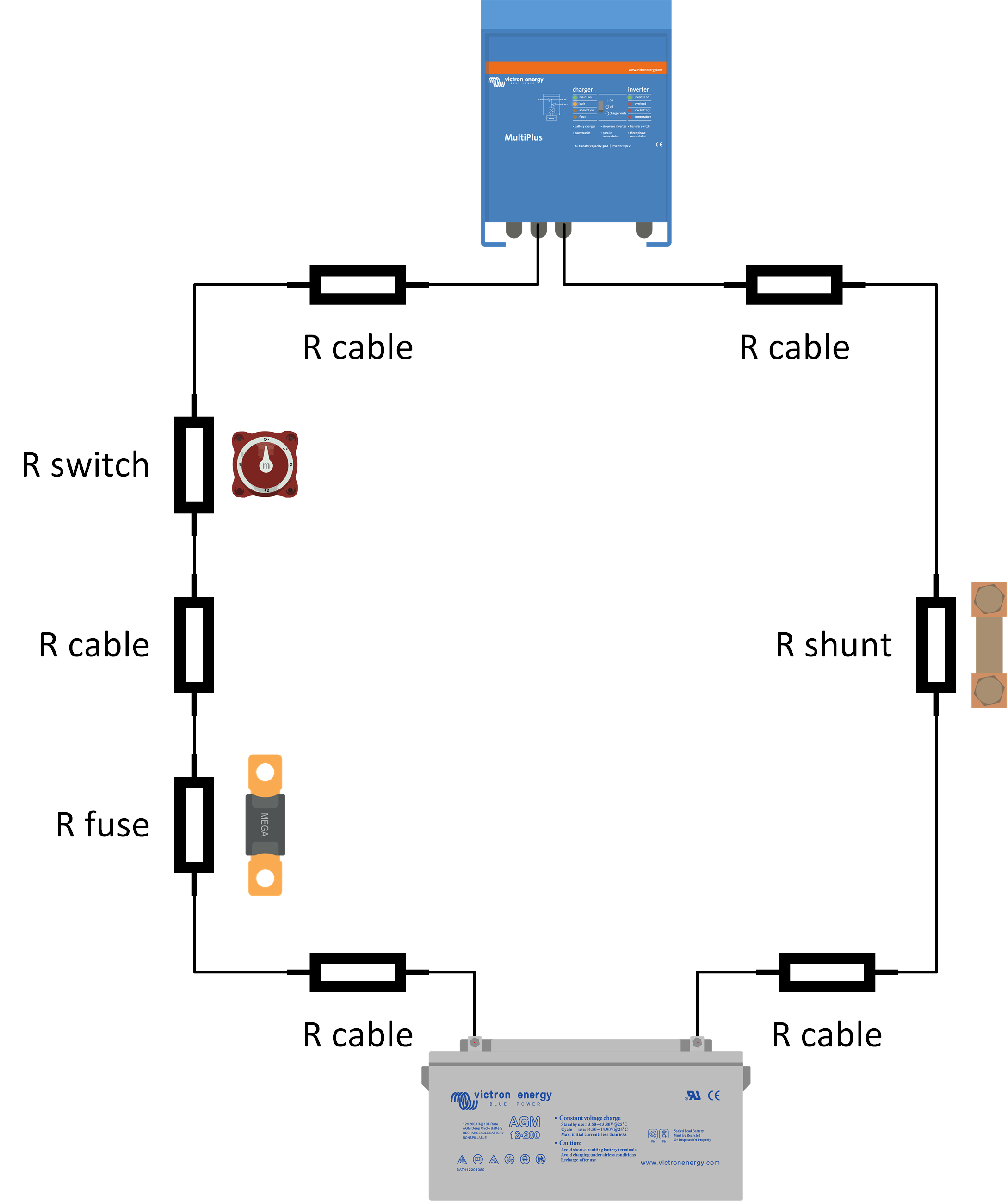
Not just the cable resistance, but other factors create resistance as well: It is important to realise that resistance does not only occur in the cable itself. Additional resistance is created by any items in the path the current has to flow through. A list of possible items that can add to the total resistance:
And especially watch out for:
Resistance will be added to the electrical circuit each time a connection is made, or if something is placed in the path between the battery and the inverter. A list of possible items that can add to the total resistance:
 |
2.8. The negative effects of cable voltage drop
We now know what we need to do to keep resistance in a circuit low in order to prevent a voltage drop. But what are the negative effects if there is a high voltage drop in a system? |
These are the negative effects of a high voltage drop:
|
This is how to prevent voltage losses:
|
It is good practice to measure the system voltage drop once you have completed an electrical installation that contains batteries. Remember that a voltage drop typically occurs during a high current event. The voltage drop becomes larger when the current increases. This is the case when an inverter is loaded with maximum load or when a battery charger is charging at full current. |
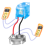
How to measure voltage drop, for example, in a system with an inverter:
| 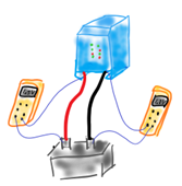 |
How to measure voltage drop when the battery is too far away or in a different room or enclosure:
|  |
2.9. Ripple voltage
One of the negative effects of a high voltage drop in a system is ripple. Ripple occurs in systems with an inverter: Ripple appears in a system where the power source is a battery (DC) and the load is an AC device. This is always the case in a system with an inverter. The inverter connects to batteries, but it powers an AC load. |
|
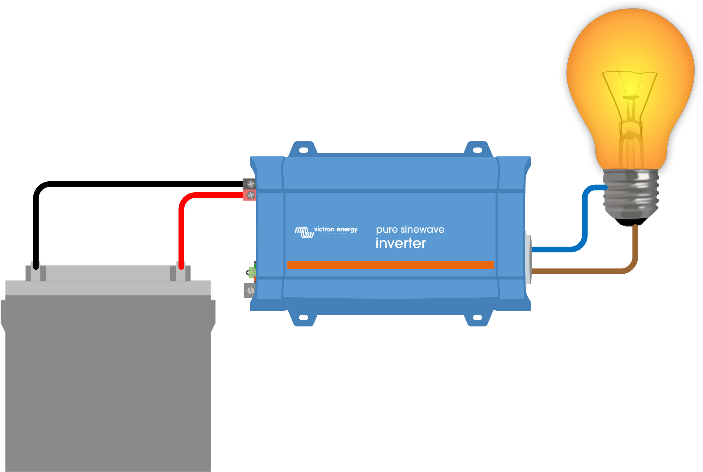
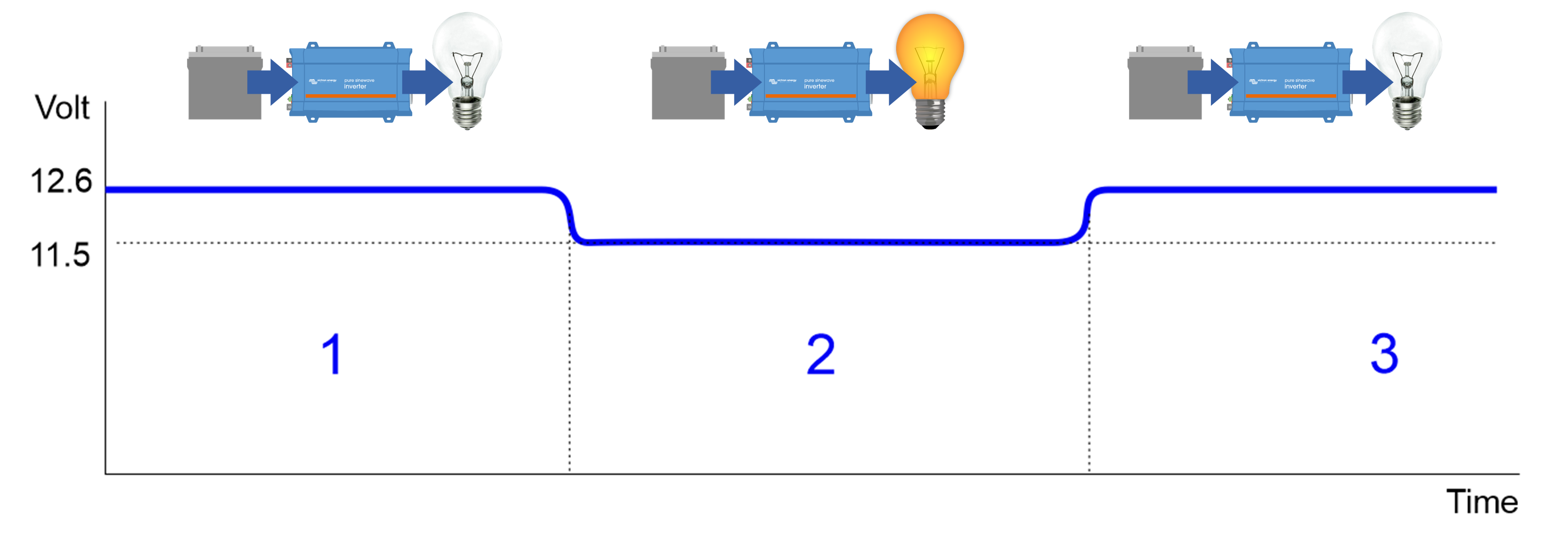
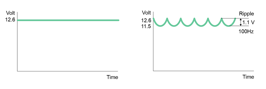
Voltage drop is the mechanism behind ripple: The mechanism that causes ripple is directly related to the voltage drop over the DC cables when a system is under load, and the battery currents are high. A high current causes a high voltage drop, this becomes particularly exaggerated when thin cables have been used. The voltage drop in a system as a whole can be even bigger, especially if lead acid batteries are used that are too small, too old or damaged. The voltage drop will not only occur over the cables but also within the battery itself. Ripple is related to the phenomenon that when an inverter is powering a large load, the system DC voltage drops. But the system voltage recovers once the load has been turned off. This process is depicted in the below image. | ||
|
| |
How is ripple created? The following steps follow the sequence of how ripple is created: | ||
1. The inverter converts a DC voltage into an AC voltage. | 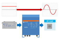 | |
2. The load connected to the inverter creates an AC current in the inverter. | 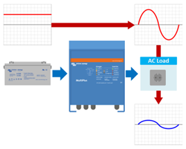 | |
3. This AC current causes (via the inverter) a fluctuating DC current on the battery. | 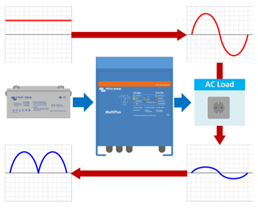 | |
4. The result of this fluctuating DC current is the following:
| 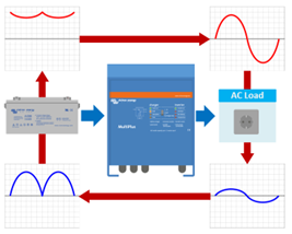 | |
The DC voltage will keep going up and down and is not constant anymore. It now is fluctuating. It will go up and down 100 times per second (100Hz). The amount the DC voltage is fluctuating is called ripple voltage. |
| |
How to measure ripple: When measuring ripple, remember that this only occurs when the system is under full load. Ripple can only be detected when the inverter is powering a full load or when a charger is charging at a high current. The same applies when measuring the voltage drop, Ripple can be measured in these two ways:
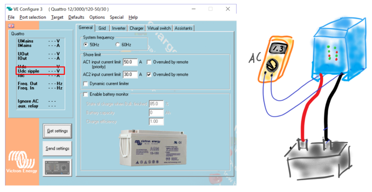 |
The negative impacts of ripple: A small amount of ripple can exist with no measurable impact. However, excessive ripple can have a negative impact. The negative impact of excessive ripple:
|
Ripple alarms: Inverters or inverter/chargers have a built-in ripple alarm. There are two ripple alarm levels:
These are the ripple alarm levels for inverter/charger models at the different DC voltages and the MultiPlus Compact regardless of voltage:
*) All voltages are RMS voltages. |
How to fix ripple: Ripple will only occur when there is a voltage drop in a system. To fix ripple voltage issues, you will have to reduce the voltage drop. This means that you have to reduce the resistance in the path from the battery to the inverter and back to the battery. For more information, see the Current, cable resistance and voltage drop chapter. | |
To fix high ripple in a system do the following:
|  |