7. Ground, earth and electrical safety
Ground or earth provides a common return path for electric current in an electric circuit. It is created by connecting the neutral point of an installation to the general mass of the earth or a chassis. Grounding is needed for electric safety and it also creates a reference point in a circuit to which voltages are measured. |
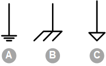
Generally speaking, there are 3 types of grounding, namely:
|
| |
|  |
7.1. Electrical safety
Electricity is dangerous, it can kill, injure or burn a person. It is the current that is the most dangerous part of electricity. A small current running through a person can already be very dangerous. See the below table. |
Electric current (1-second contact) | Physiological effects |
|---|---|
1mA | Threshold of feeling a tingling sensation. |
5mA | Accepted as maximum harmless current. |
10 - 20mA | Beginning of sustained muscular contraction ("can not let go"current). |
100 - 30mA | Ventricular fibrillation, this is fatal if continued. The respiratory function continues. |
6A | Sustained ventricular contraction followed by normal heart rhythm (defibrillation). Temporary respiratory paralysis and possibly burns. |
Current will flow as soon as an electric circuit is closed. For example, imagine two loose AC wires, a live and a neutral wire. When the wires are just hanging there, no current will flow because the circuit is not closed. But as soon as you touch a live wire with one hand and the neutral wire with another hand you have closed the circuit and electricity will flow from the live wire, via your body and via your heart, back to the Neutral wire. The current will keep flowing until the fuse blows, but by then you are probably already dead. |
 |
|
| ||
Exposed electrical wires. | The electric circuit is not closed and electricity cannot flow. | The electric circuit is closed and electricity will flow. |
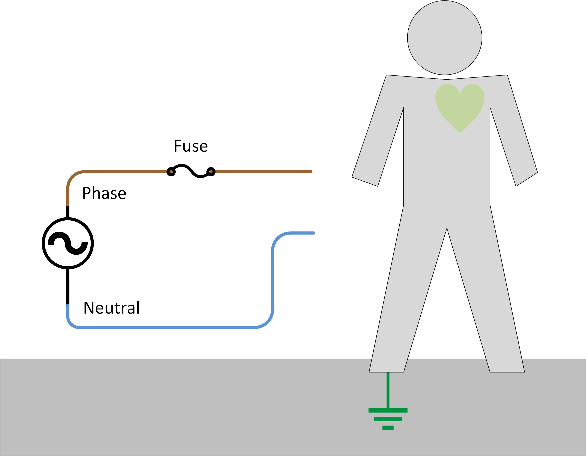
Apart from touching a neutral and a live wire at the same time, there is another way in which an unsafe situation can occur and that is when the electricity flows via earth. This is a more common situation to occur, than someone touching a phase and neutral conductor at the same time. The neutral conductor is connected to earth at some point. This can be in the house installation, in the distribution network or at the power generator (the star point). |
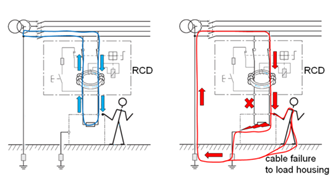
If there is a fault in electric equipment the metal parts of the outside of that equipment can become live. This can be because there is an internal shortcut between live electricity and the equipment’s metal housing. Think for example of a faulty washing machine. A fault can have been caused because there is an electrical fault, mechanical damage, or damaged electrical wires that are touching the metal housing of the electrical equipment. The moment you touch the faulty washing machine, electricity will flow from phase to the metal housing, via you, to earth. From the earth, the electricity will then flow into the Neutral of the mains supply. The circuit is complete. Electricity will keep flowing until the fuse in the mains supply has blown. But like in the previous situation, you are probably already dead. | 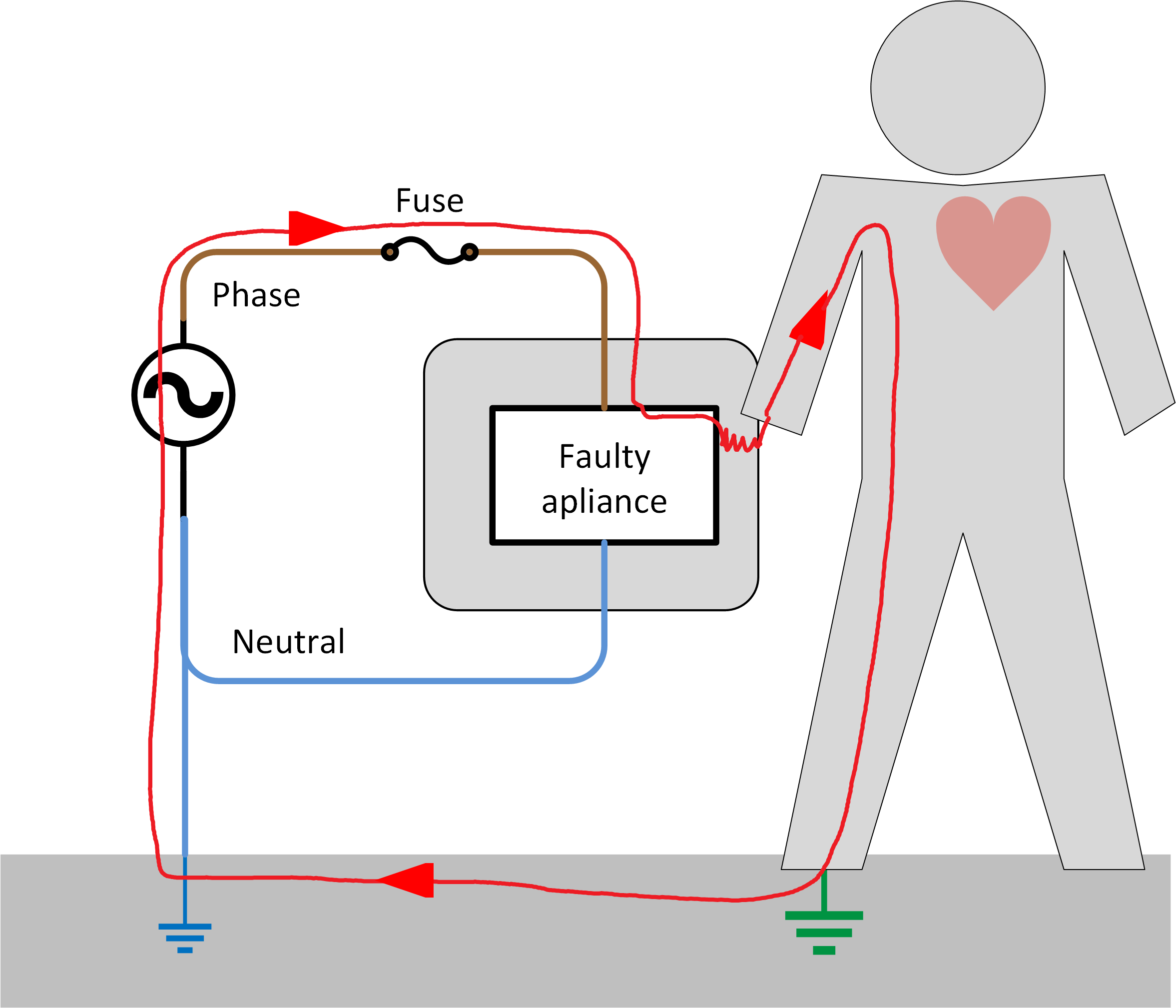 |
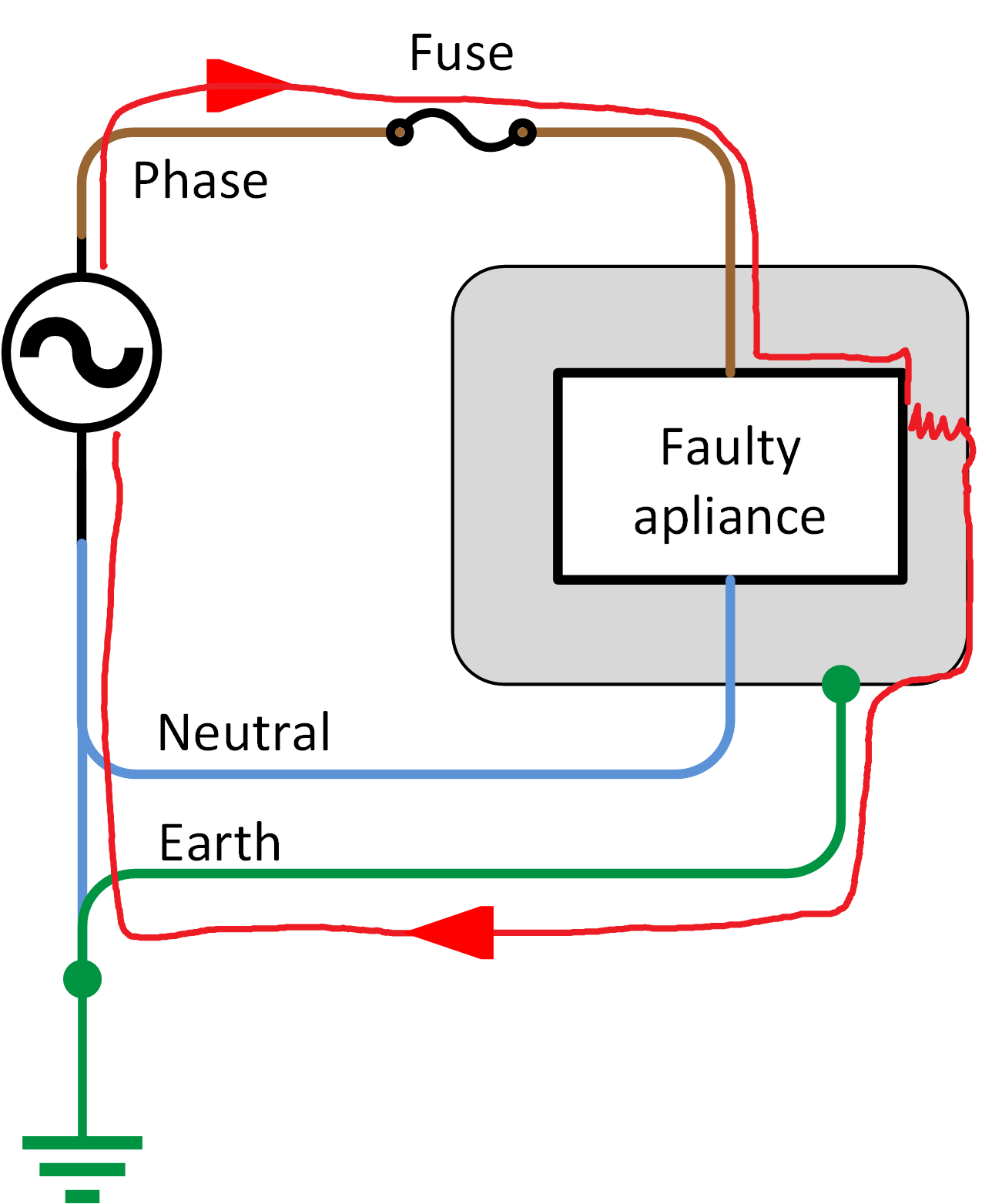
To make electrical installations safer the earth conductor was introduced. The earth wire connects the metal housing to earth. If you now touch the faulty equipment, electricity will flow into the earth wire rather than into you. The reason for this is that electricity will travel through the path of least resistance. The path via you and the earth is a more resistive path than via the earth wire. But be aware that a very small amount of current can still flow via a person. A current greater than 30 mA can already be dangerous. Note that just an earth wire is not enough. A residual current device (RCD) is also needed in an installation. See chapter RCD, RCCB or GFCI for more information. | 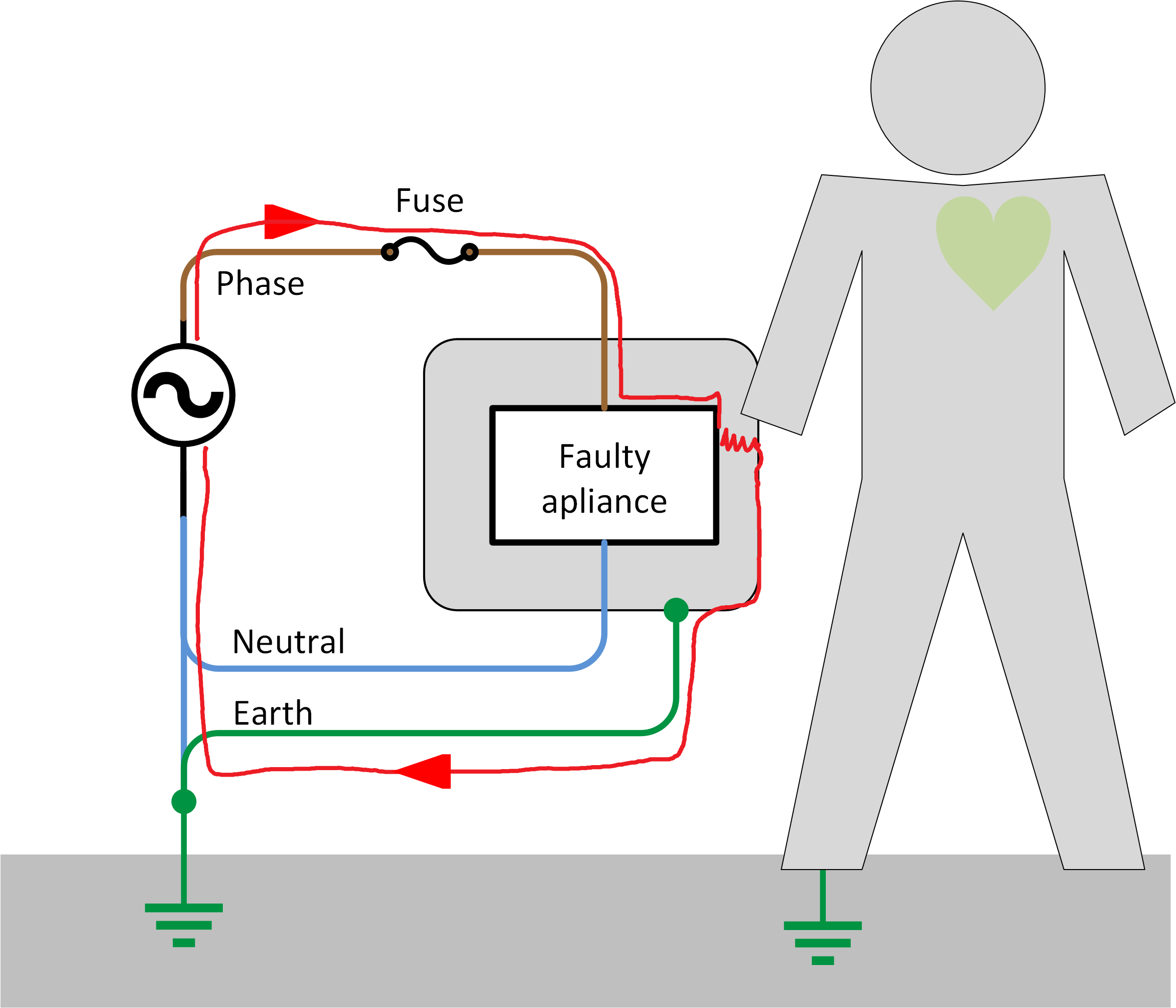 |
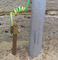
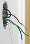
7.2. Earth wiring
Good earth wiring is essential to electrical safety. The wire and the earth connections must be of low electrical resistance. Remember that electricity will travel through the path of least resistance. So, you have to make sure that the earth cable is thick enough and all connections are tight. The earth wire can have potentially large currents flowing through it when there is an equipment fault. The earth wire needs to be able to carry this current until the system fuse blows. So it is important that the earth wire is thick enough. Earth or ground wires are yellow/green. In older installations or in different countries you might also see a green wire. |
| |
CautionCAUTION: Always follow the local wiring regulations for the correct earth wire sizing. | ||
7.3. RCD, RCCB or GFCI
Electricity can be very dangerous. Adding an earth conductor into a system improves safety, but an installation can be made even safer by incorporating an RCD (residual current device). The use of an RCD is compulsory in all AC installations. |
RCD function: The RCD detects and disconnects as soon as it detects that electricity is flowing into earth. Electricity will flow into earth if there is a fault in the system, or more importantly when current is flowing through a person. RCDs are designed to disconnect as soon as a current flow to earth is detected. A residual current device (RCD) can be known under different names:
|
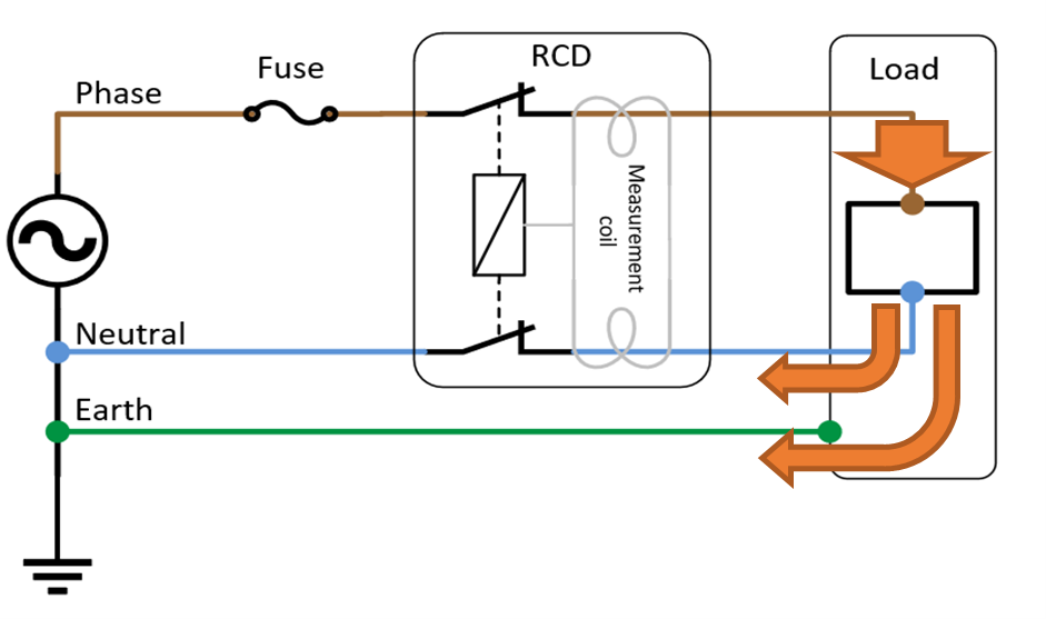
RCD operation: An RCD measures the current balance between the phase and the neutral conductor. The device will open its contact when it detects a difference in current between phase and neutral. In a safe system, the supply and return currents must sum to zero. If this is not the case there is a fault in the system, current is leaking to earth or to another circuit. |
| |
RCDs are designed to prevent electrocution by detecting this leakage current, which can be far smaller (typically 5 - 30mA) than the currents that are needed to trip conventional circuit breakers or fuses (several Amperes). RCDs are intended to operate within 25 - 40 milliseconds. This time is faster than the time needed for the electric shock to drive the heart into ventricular fibrillation, the most common cause of death through electric shock. A safe system is a system that protects against short-circuit, overload and earth leakage currents. |
| |
Earth leakage detection can only take place in systems where the neutral conductor is connected to the earth conductor; like in a TN or TT system. Earth leakage detection is not possible in an IT network. | ||
Where to mount an RCD An RCD must be mounted before the loads in an electrical installation. In reality, this means that the RCDs have to be mounted before the installation is split up into different groups. If an inverter or inverter/charger is used, the RCD should come after this, otherwise, there will be no earth protection while the inverter is operational. Consumers that are only operational when connected to shore power will need their own RCD. |
Nuisance Tripping of RCDs In some installation RCD’s will trip prematurely. This can be caused by the following:
|
7.4. Neutral to earth link in inverters and in inverter/chargers
An AC power source needs to have a neutral-to-earth link (MEN link) so that an RCD can operate. This is the case for the grid, but also if the AC source is a generator or an inverter.
But when combination inverter/charger units are used, the MEN link is less straightforward. The inverter/charger unit has two different modes of operation:
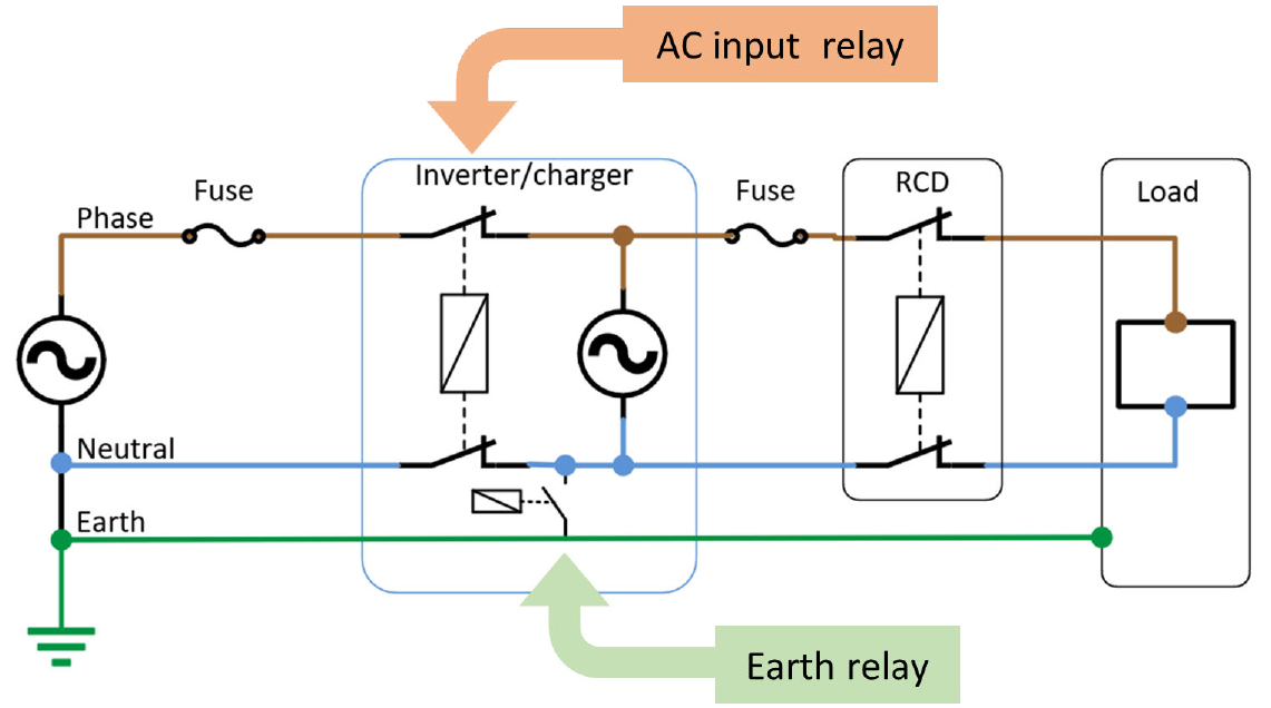
When the inverter/charger is inverting and acting as a power supply, it will have to make an independent MEN link. But when it is feeding through a generator or grid supply, the incoming supply has to have the MEN link instead of the inverter/charger. Victron inverter/chargers contain an internal ground relay. This relay automatically makes or breaks the connection between earth and neutral. If this is not desired, this relay can be turned off in the inverter/charger settings. Note that if the relay is turned off, you will have to hard-wire a neutral-to-earth link in the system. Likewise, in some installations, it might not be allowed to break the neutral conductor, in that case, provided an inverter/charger-II is used, choose a grid-code setting of a type that states that the AC neutral path is externally joined. |
The inverter/charger is in charger mode and/or feed-through mode: When the inverter is connected to AC power the AC input relay is closed and at the same time, the earth relay is open. The AC output system relies on the AC power supply to provide the neutral-to-earth link. This link is needed so the RCD in the AC output circuit is operational. Earth relay AC input relay
|
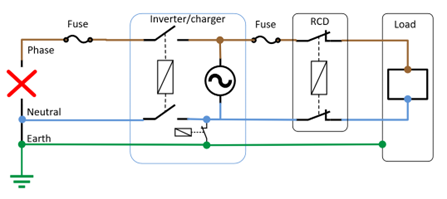
The Inverter/charger is in inverter mode: When the AC power supply is disconnected, has been turned off, or has failed, the AC input relay opens. When the AC input relay is open, the installation does not have a neutral-to-earth link anymore. This is why at the same time the earth relay is closed. As soon as the earth relay closes the inverter/charger has made an internal neutral-to-earth link. This link is needed so the RCD in the AC output circuit is operational.
|
7.5. Mobile installations
A mobile installation is an installation that operates independently from the grid. When it connects to AC power, it usually connects to the grid at different locations and/or generators. For example, boats, vehicles or mobile backup power systems. In this chapter, a boat installation is used. However, this information can be used for any mobile installation. A mobile system does not have an earth stake. So, something else in its place is needed to create a central earth potential. All touchable metal parts of the boat or vehicle must be connected to each other to create a local earth. Examples of metal parts in a boat or vehicle are: chassis, hull, metal fluid pipes, railing, engine, power socket earth contacts, lightning conductors and the earth plate (if present). A mobile system typically connects to a variety of power sources. In these situations it is sometimes not clear which of the leads in the shore power supply is connected to earth or if the earth is connected at all. Also, phase and neutral may not have been wired correctly. Connecting a supply like this to a mobile system can potentially create a short circuit to earth. Or the earth is missing completely. It also matters if the mobile system connects to power or if it is disconnected from power and running autonomously. Some examples of different situations a mobile system can be in: |
A boat is connected to shore power When a boat is moored and connected to shore power installation is similar to a residential installation. There is only one difference; the boat does not have its own earth connection; like the earth spike you will find in a house. The boat installation relies on the earth provided by the shore connection. Unfortunately, this earth is not always reliable due to the fact that the marina cables are often long and might have an insufficient cable core thickness. To create a safe situation, the metal parts of the boat, like the hull, will have to be connected to the incoming earth from the shore power cable. The shore power earth is connected to neutral. If an earth leakage occurs, current will flow through the earth conductor in the mains cable, but also via the hull via the water and back to shore earth. Both earth leakage circuits have the same potential and are in a way connected in parallel. But more current will flow through the earth conductor in the shore cable. The path through the hull and the water has got a bigger resistance. The RCD will still trigger an earth fault because it will compare phase current in versus current out via neutral. | 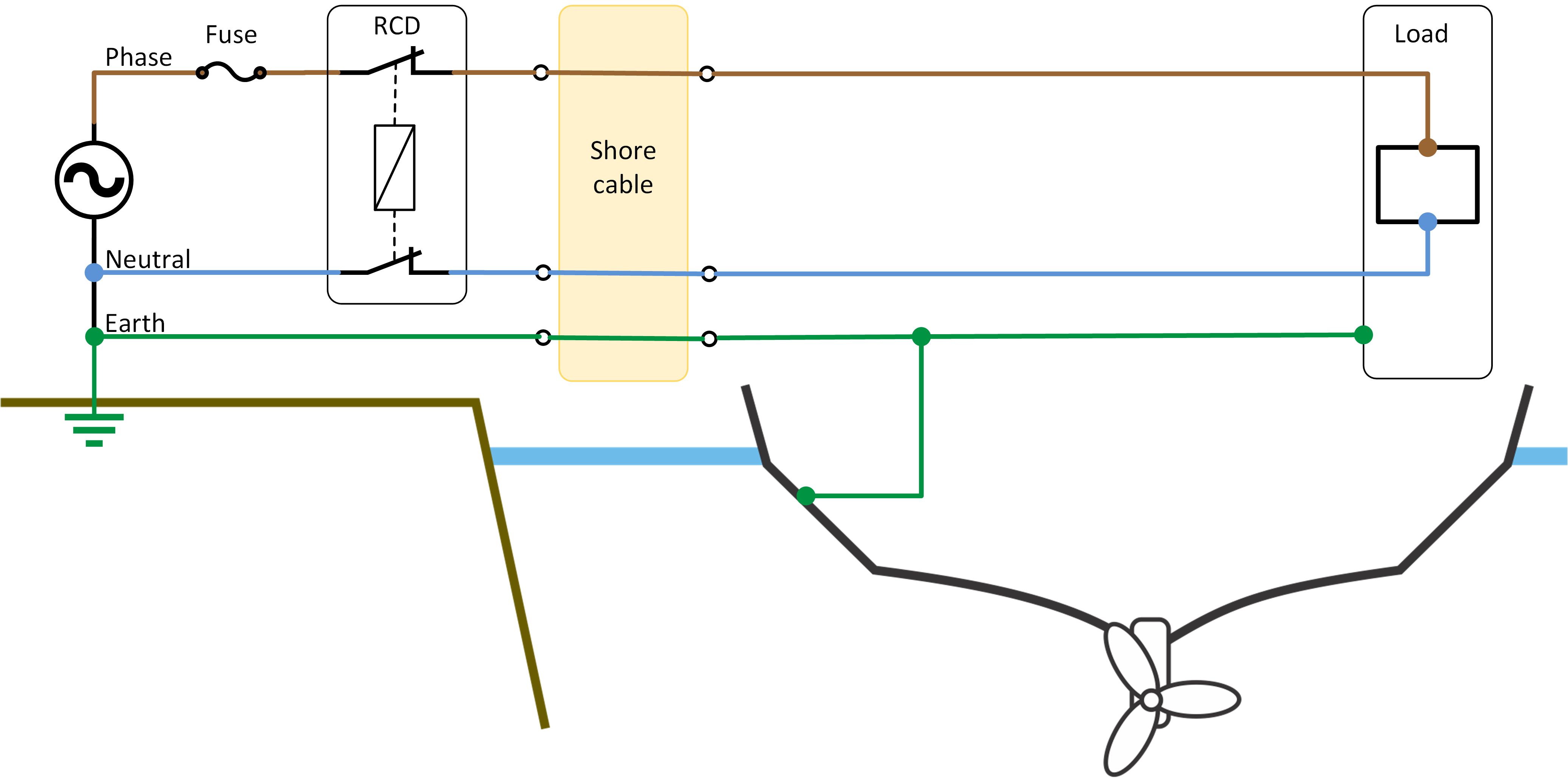 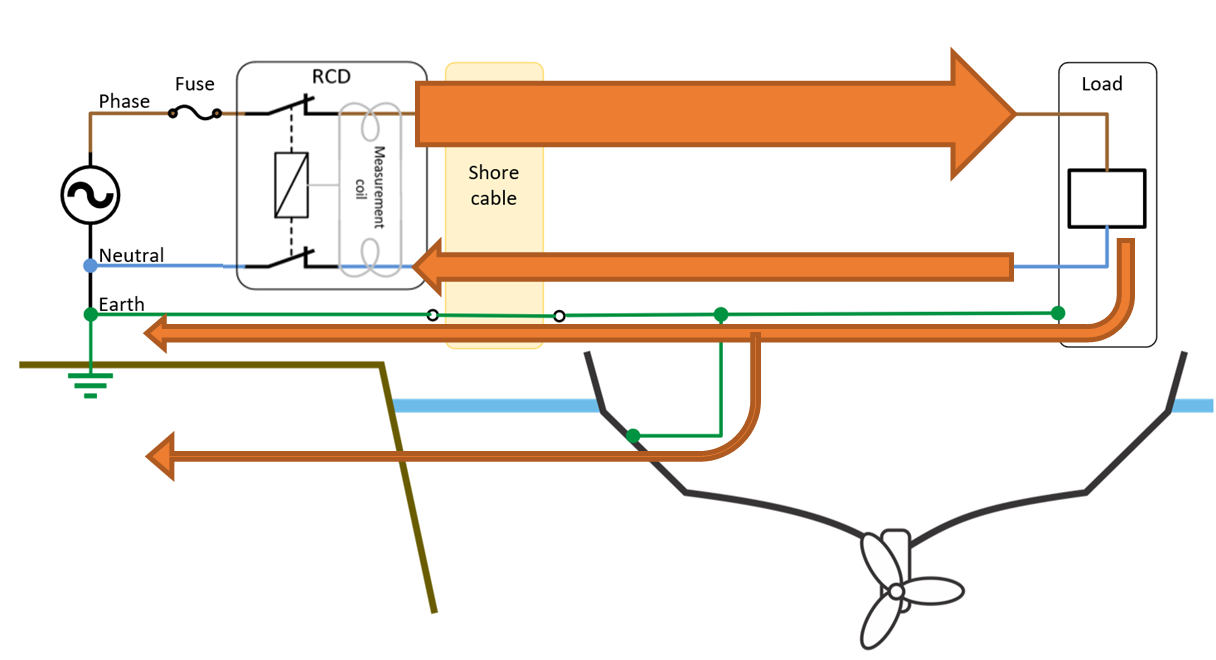 |
A boat is disconnected from shore power As soon as the boat disconnects from shore power the entire installation changes because the installation is now not part of the grid anymore and the connection with neutral and earth are lost. The installation is now the main power supply and together with the load forms its own autonomous electric circuit. No current will flow into the hull and into the water. | 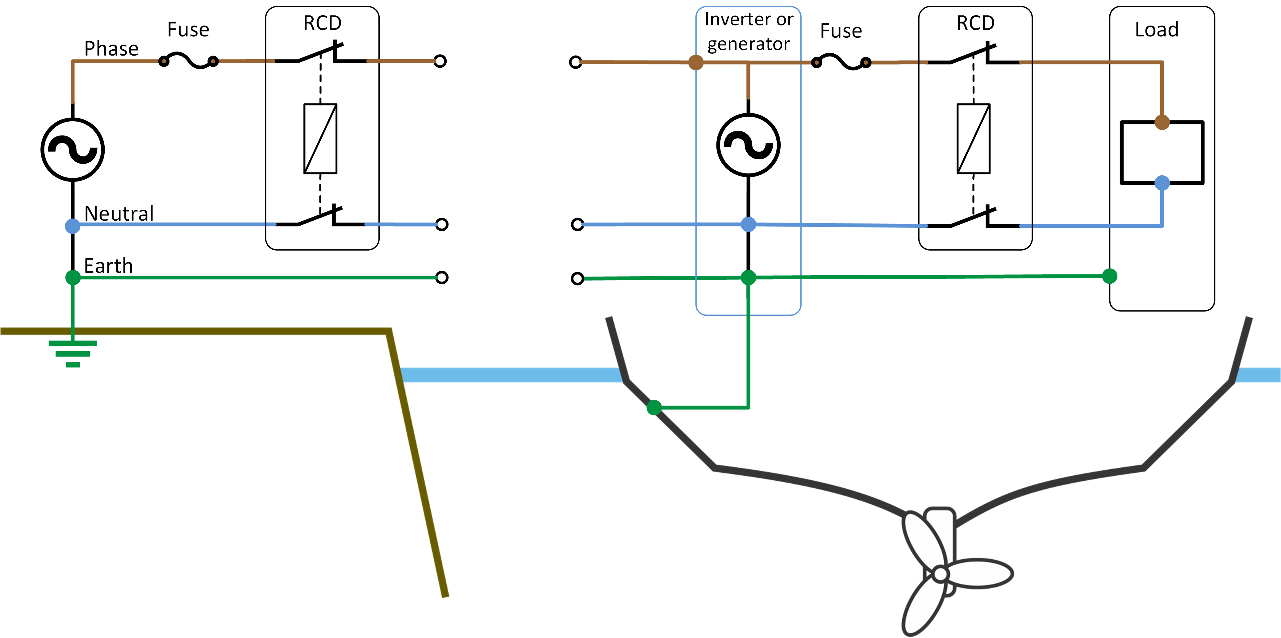 |
Floating network in boat or vehicle (IT Network) In a mobile system where an inverter (or generator) is the only power source one can specifically choose not to use a TT network but to use an IT network. In an IT network, the phase and neutral are not coupled to another potential like earth. The voltages created by the independent power source are floating. A system like this is very safe and simple to install. If a conductor or housing in this system is touched by a person, no current can flow to earth. Remember, for current to flow a complete circuit is needed. In this system the earthing conductor is absent, and the electric circuit to earth is not complete. This is a similar situation to the safety transformer in a bathroom. Inverters and generators are in principle nothing more than the source of two potential differences with a difference of 230 Volt (or 120V). Touching will not lead to a current flow because the path is incomplete. It is the same as a bird sitting on an electricity wire. Be aware that touching both the phase and neutral wire at the same time is always dangerous because then the path is complete. | 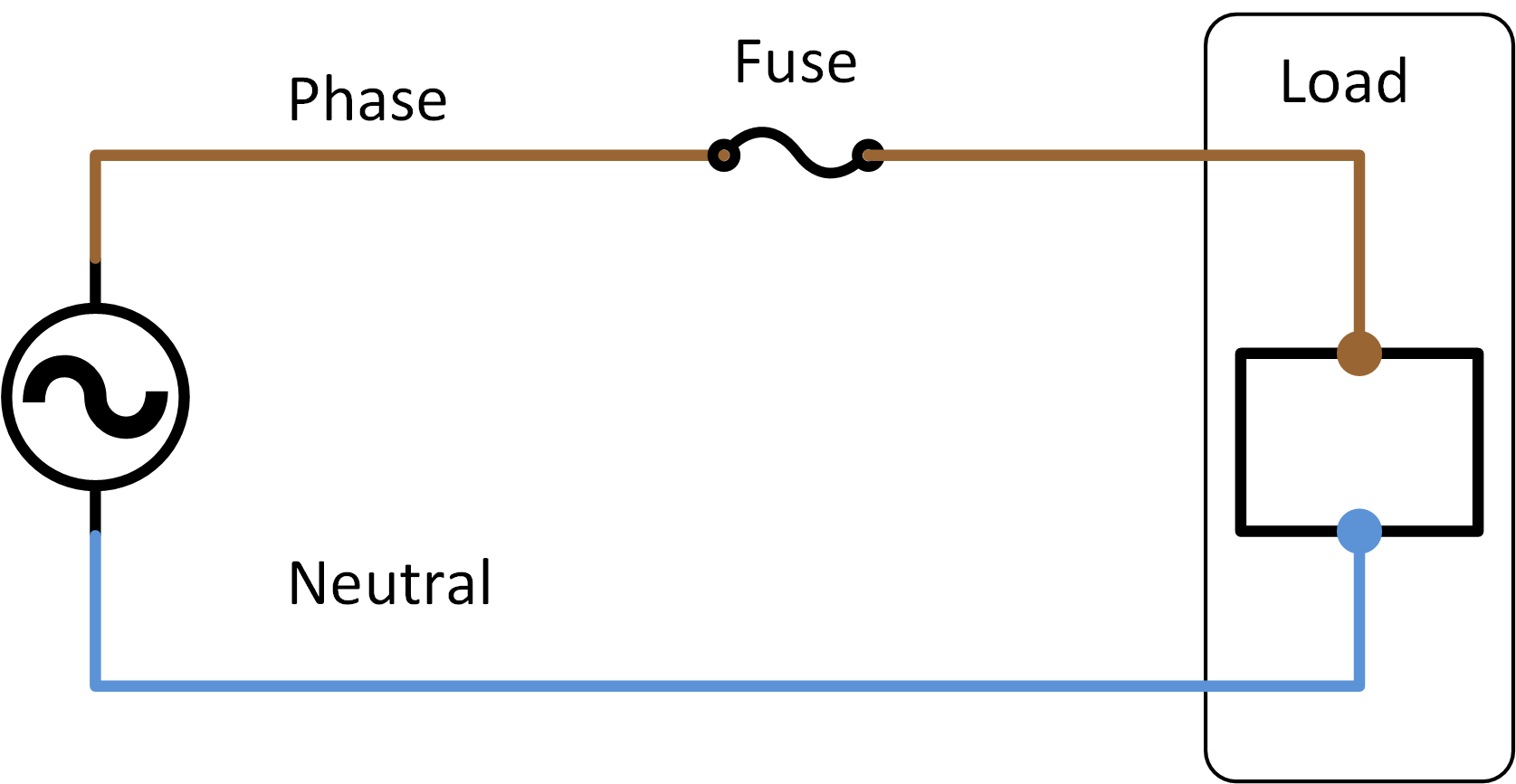  | |
 Safe, no electricity will flow | 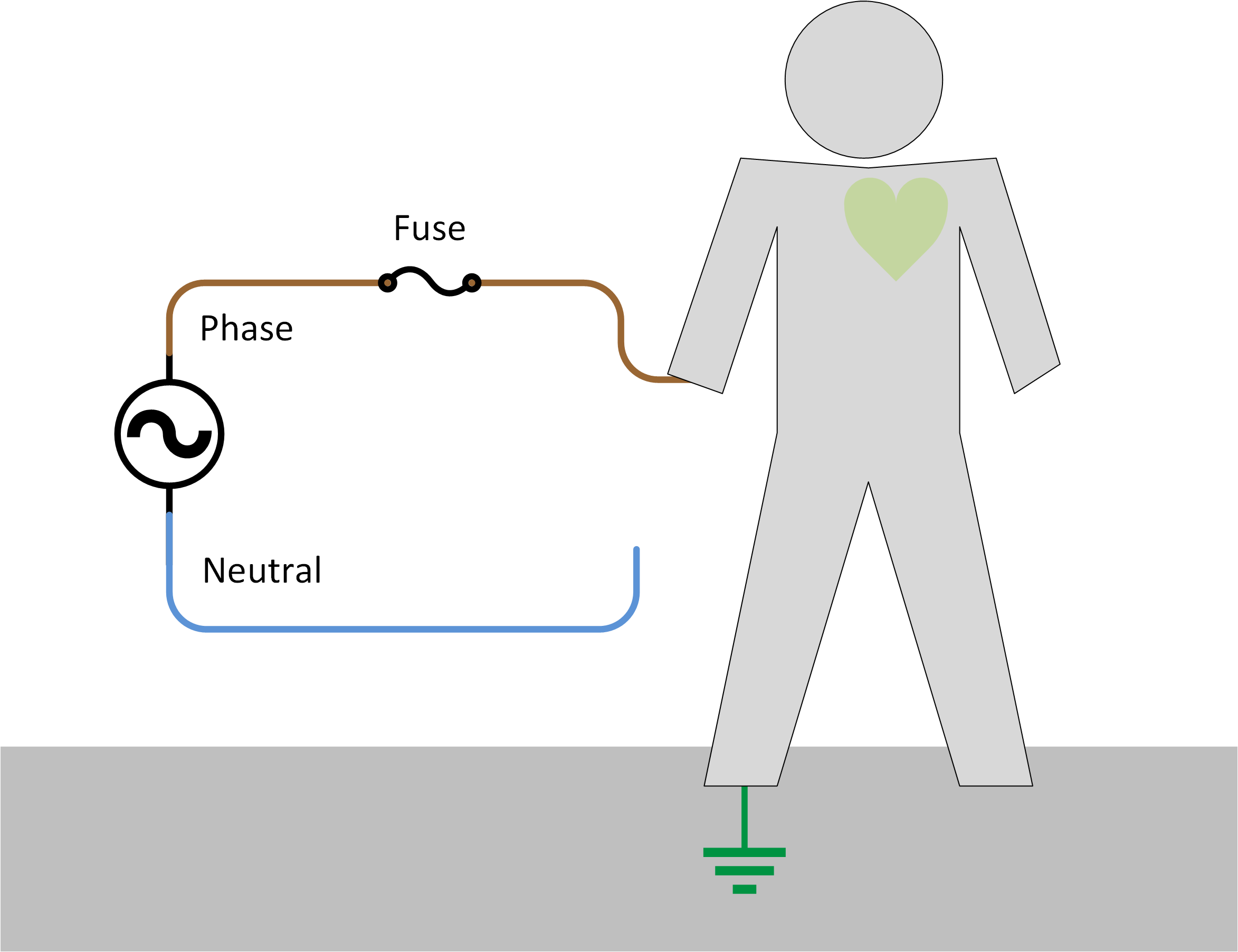 Safe, no electricity will flow | 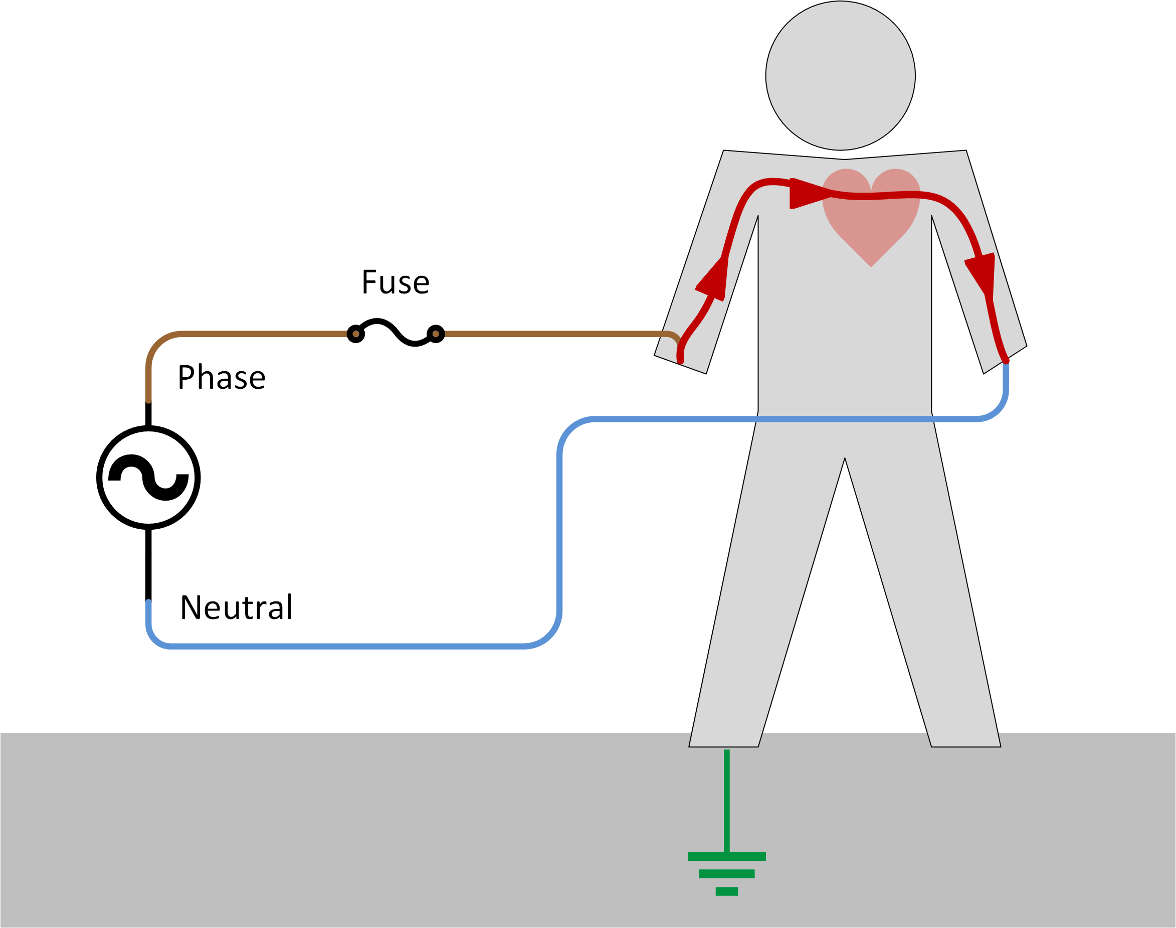 Unsafe, electricity will flow |
Mobile network with earth and neutral to earth link (TT network) If the mobile system connects to the grid via a transfer switch or via an inverter/charger, earth and a neutral to earth link is introduced into the system. It becomes a TT network. This is also the case if local regulation requires that earth, and neutral to earth link and an RCD has been hardwired in a mobile system that contains an inverter or generator. The moment this happens the system will become more dangerous, so as soon as earth and a neutral to earth link have been added to a system an RCD will need to be installed. as to satisfy the requirements of the TT or TN network where the mobile network is now connected to. | ||
No earth, no electricity will flow | 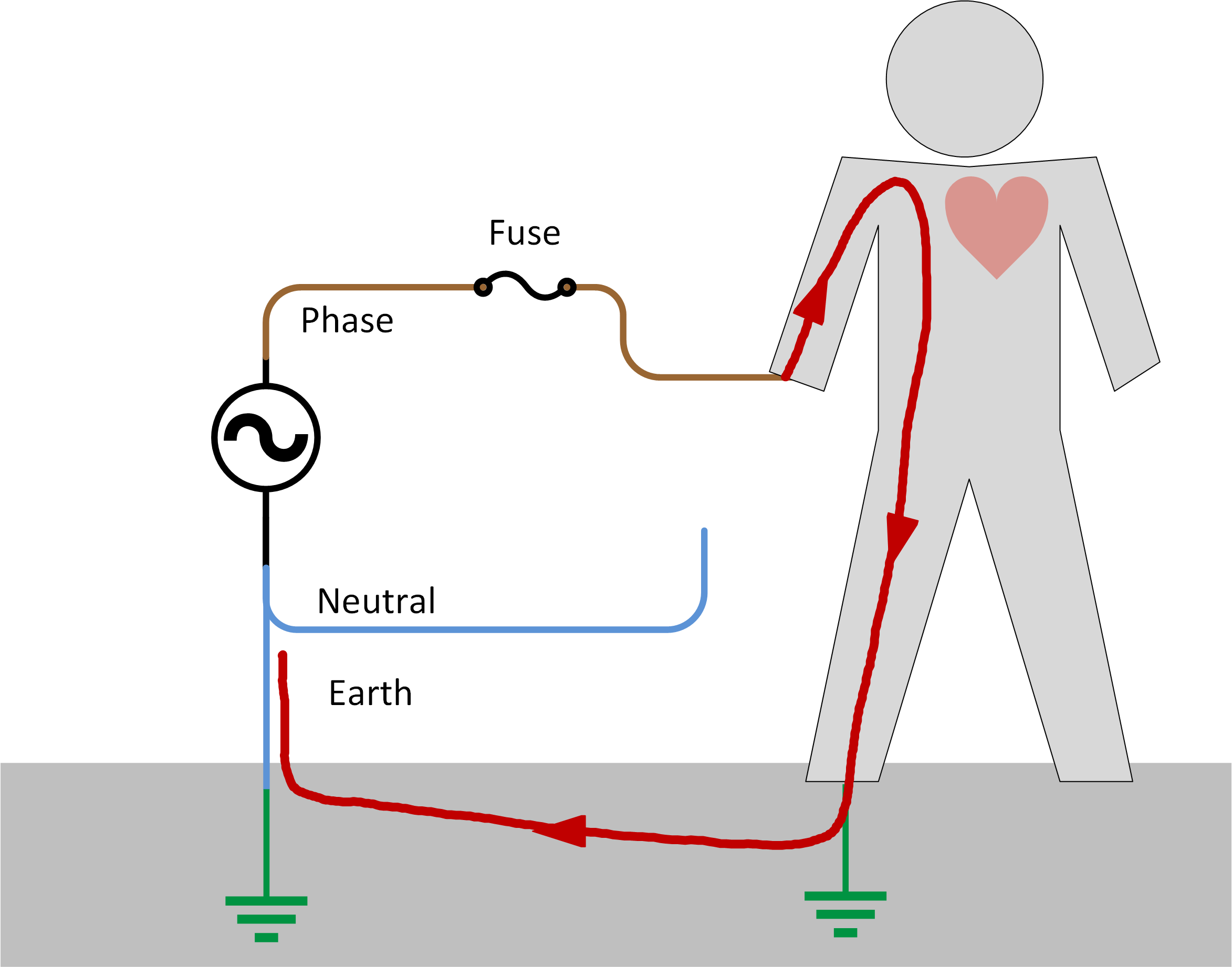 Earth added, electricity will flow | 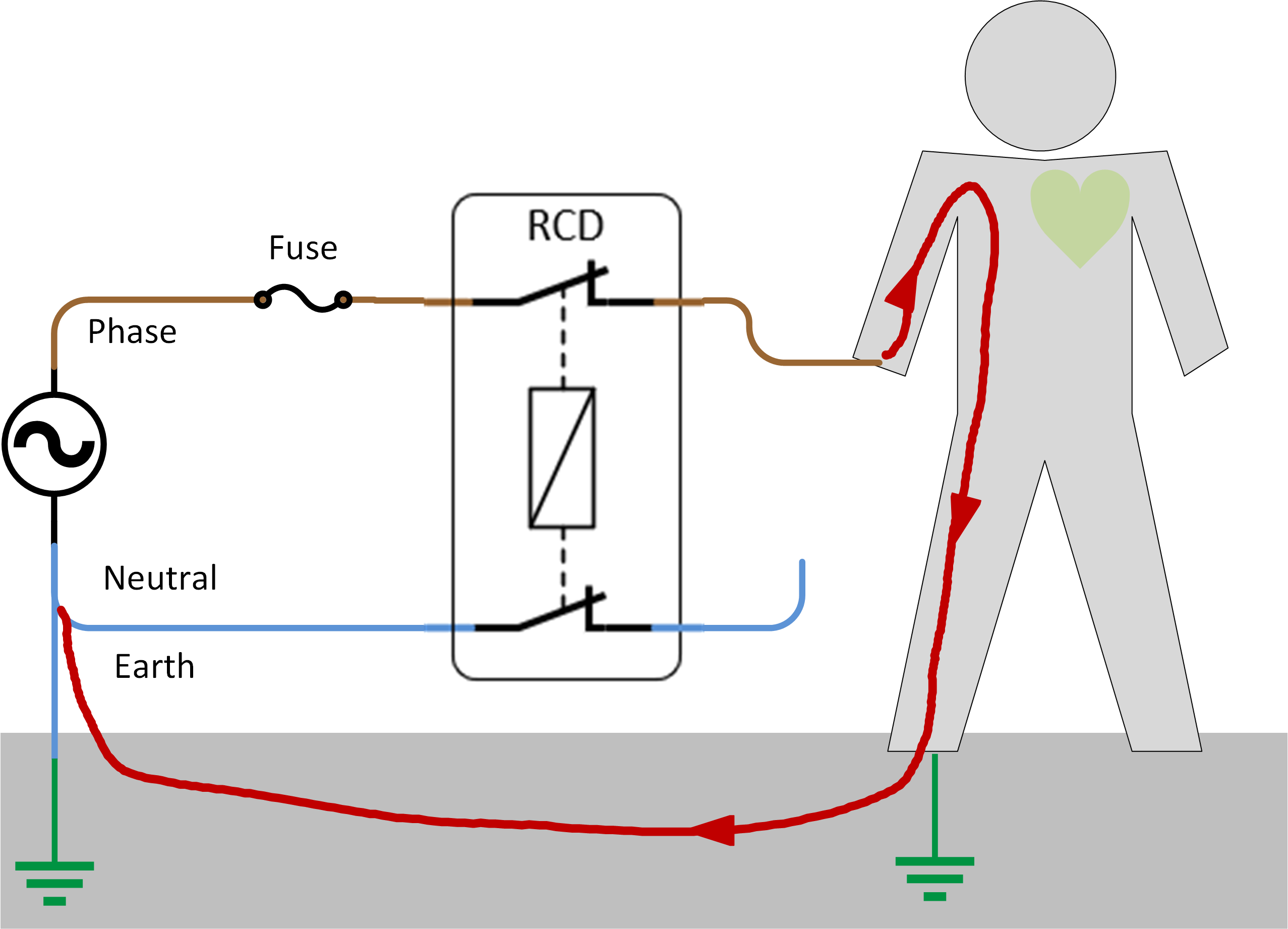 Safe, the RCD will protect in case electricity flows |
From IT network to TT network With a mobile system, it is possible to create a network that is a TT network when connected to mains and at the same time become a floating IT network when the grid is disconnected and a generator or inverter is in use. This is something that is not desired and should be avoided. When an installation disconnects from the grid, it also disconnects from the grid earth. If the mobile installation does not have earth and also no earth and neutral link it will become a floating system the moment the grid is disconnected. Although the system might have an RCD, the RCD cannot detect an earth leakage current anymore because the Neutral is not connected to earth. Pressing the test button on the RCD is useless if the neutral-to-earth link is missing. When you press the test button, you will get a false impression that the RCD is operational, while in reality, the RCD will not operate in case of an earth fault as the neutral-to-earth link is missing. When the test button on an RCD is pressed, an internal bypass is activated, simulating an earth leak, so the RCD can be electrically and mechanically tested. The test button, by no means, is a test for the whole installation. It only tests the RCD itself. This will lead to confusion and/or dangerous situations. It is for these reasons that it is recommended to always follow the principles of the TT network, also for situations when the installation is not connected to mains power. The switch from IT to TT network has to accommodate for a connection being made between neutral and mobile system earth as soon as the grid is disconnected. This can be done automatically by an inverter/charger with an earth relay or must be hard-wired into a transfer switch. Not all inverters and generators have a neutral that is connected to earth. This will always need to be checked prior to installation. And if needed a neutral-to-earth link needs to be hard-wired |
7.6. Isolation and grounding of Victron equipment
This chapter explains the isolation of a variety of Victron products between AC and DC, or between DC and DC. This information is needed so a system containing a Victron product can be grounded correctly. |
Isolation of all Victron inverters and inverter/chargers:
In the case of positive grounding, non-isolated interface connections will refer to the DC negative and not to ground. Grounding such a connection will damage the product. The AC ground terminal of all inverters and inverter/chargers is connected to the chassis. |
AC neutral grounding of Victron inverters The neutral of all inverters rated 1600VA and above and the Inverter Compact 1200VA is connected to the chassis. Grounding the chassis will therefore also ground the AC neutral. A grounded neutral is required for the proper operation of an RCD (or RCCB, RCBO or GFCI). If no reliable ground is available and/or if an RCD (or RCCB, RCBO or GFCI) is not installed, the AC neutral to chassis connection should be removed to improve safety. Warning: such an installation does probably not comply with local regulations. The AC neutral of lower power inverters is generally not connected to the chassis. A neutral-to-ground connection can be established, however: please see the product manual. |
AC neutral grounding of Victron inverter/chargers The output AC neutral of all inverter/chargers is connected to the input AC neutral when the back-feed relays are closed (AC available on input). When the back-feed relays are open, a ground relay connects the outgoing neutral to the chassis. A grounded neutral is required for the proper operation of an RCD. Disabling the ground relay is possible on most models. Please see the product manual. |
Isolation of MPPT solar chargers There is no isolation between PV input and DC output. There is basic isolation between input/output and chassis. |
Isolation of other products Battery chargers: reinforced isolation between AC and DC. Basic Isolation between AC and chassis, except for the Smart IP65 chargers which have reinforced isolation between AC and the plastic casing. DC-DC converters, diode and FET splitters and other DC products: the casing is always isolated from the DC (basic isolation). |
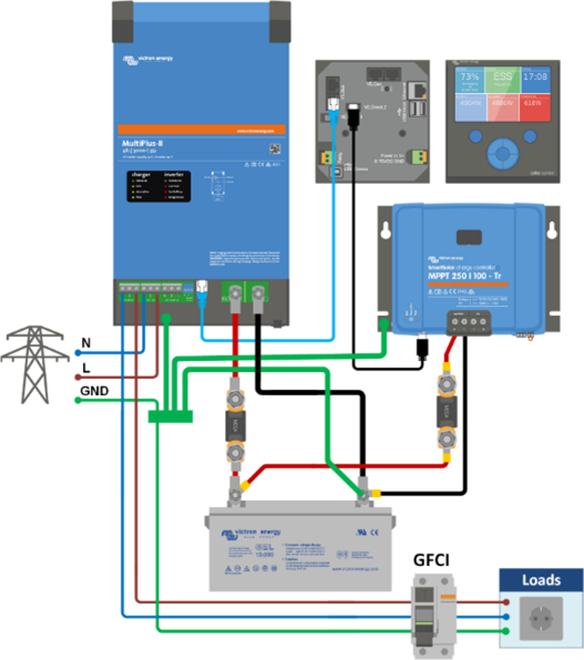
7.7. System grounding
Thus far we discussed AC earth or ground in AC installations, but grounding is also needed for the DC components in an installation. This chapter describes some common installations that contain not only an inverter/charger but also a battery bank, solar charger and a PV array. |
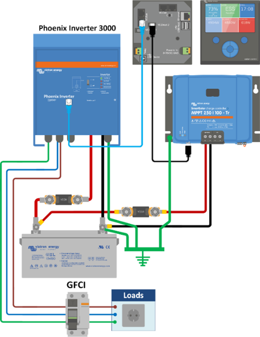
Off-grid system grounding Do not ground the positive or negative of the PV array. The PV negative input of the MPPT is not isolated from the negative output. Grounding the PV will therefore result in ground currents. The PV frames however may be grounded, either close to the PV array or (preferably) to the central ground. This will provide some protection against lightning. Ground close to the battery. The battery poles are supposed to be safe to touch. The battery ground should therefore be the most reliable and visible ground connection. The DC ground cabling should have a sufficient thickness to be able to carry a fault current at least equal to the DC fuse rating. The chassis of the inverter or Multi/Quattro must be grounded. There is basic insulation between AC and chassis. The chassis of the MPPT solar charger must be grounded. There is basic insulation between AC and chassis. Please note that the AC distribution with fuses or MCBs and PV array and PV frame grounding are not shown. |
|
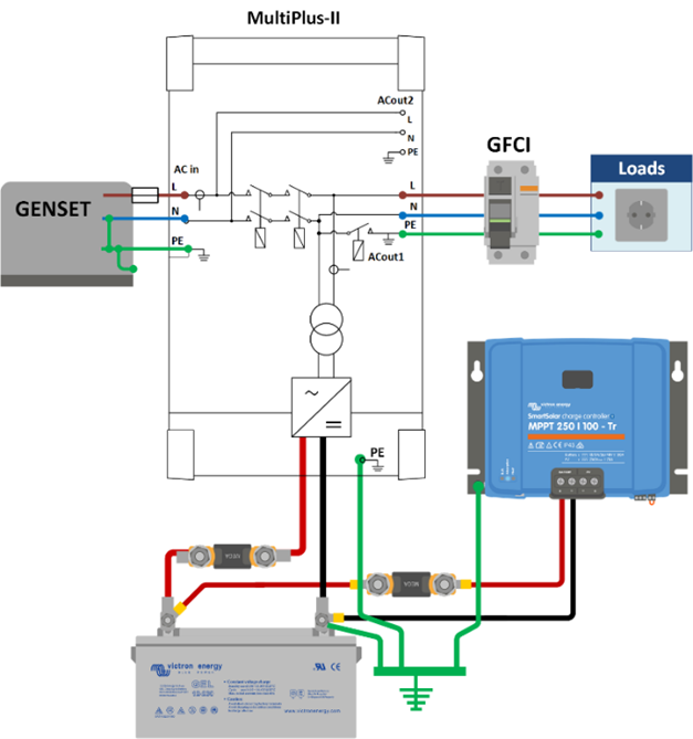
Off-grid with generator Use one ground only, close to the battery. The battery poles are supposed to be safe to touch. The battery ground should therefore be the most reliable and visible ground connection. The DC ground cabling should have a sufficient thickness to be able to carry a fault current at least equal to the DC fuse rating. Similarly, AC ground cabling should be able to carry a fault current at least equal to the AC fuse rating. A GFCI will be functional only if the chassis of the Multi/Quattro is grounded. |
|
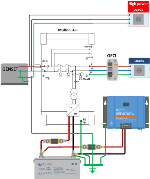
Off-grid with high power generator Ground the generator directly at the central ground. |
|
Grid-connected Energy Storage System (ESS) The DC ground cabling should be able to carry a fault current at least equal to the DC fuse rating. Connect the chassis of the inverter/charger to the ground busbar The AC-out ground may be taken from the central busbar or from the AC-out terminal. |
|