3. Battery bank wiring
At the heart of any Victron system sits the battery. This is either a single battery or a number of interconnected batteries. CautionCAUTION: Battery terminals are not insulated. To prevent short circuits or electric shock use insulated tools and do not wear metallic jewellery, |
3.1. The battery bank
Batteries are interconnected to increase the battery voltage or to increase the battery capacity or both. Multiple interconnected batteries are called a battery bank. |
The following applies to battery banks:
|
Some examples: | |||
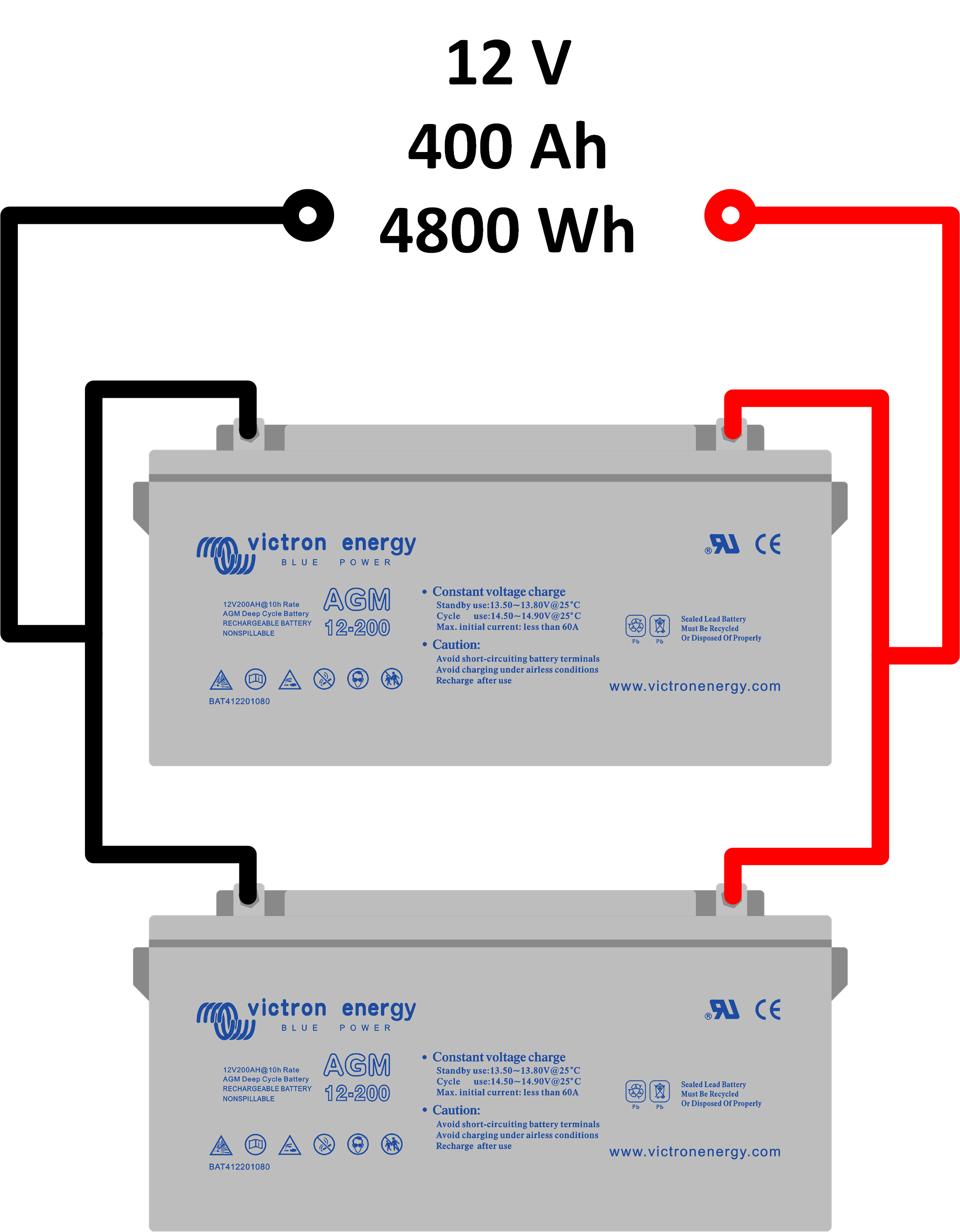
 Single battery. |  Two batteries in series. | ||
Two batteries in parallel. |
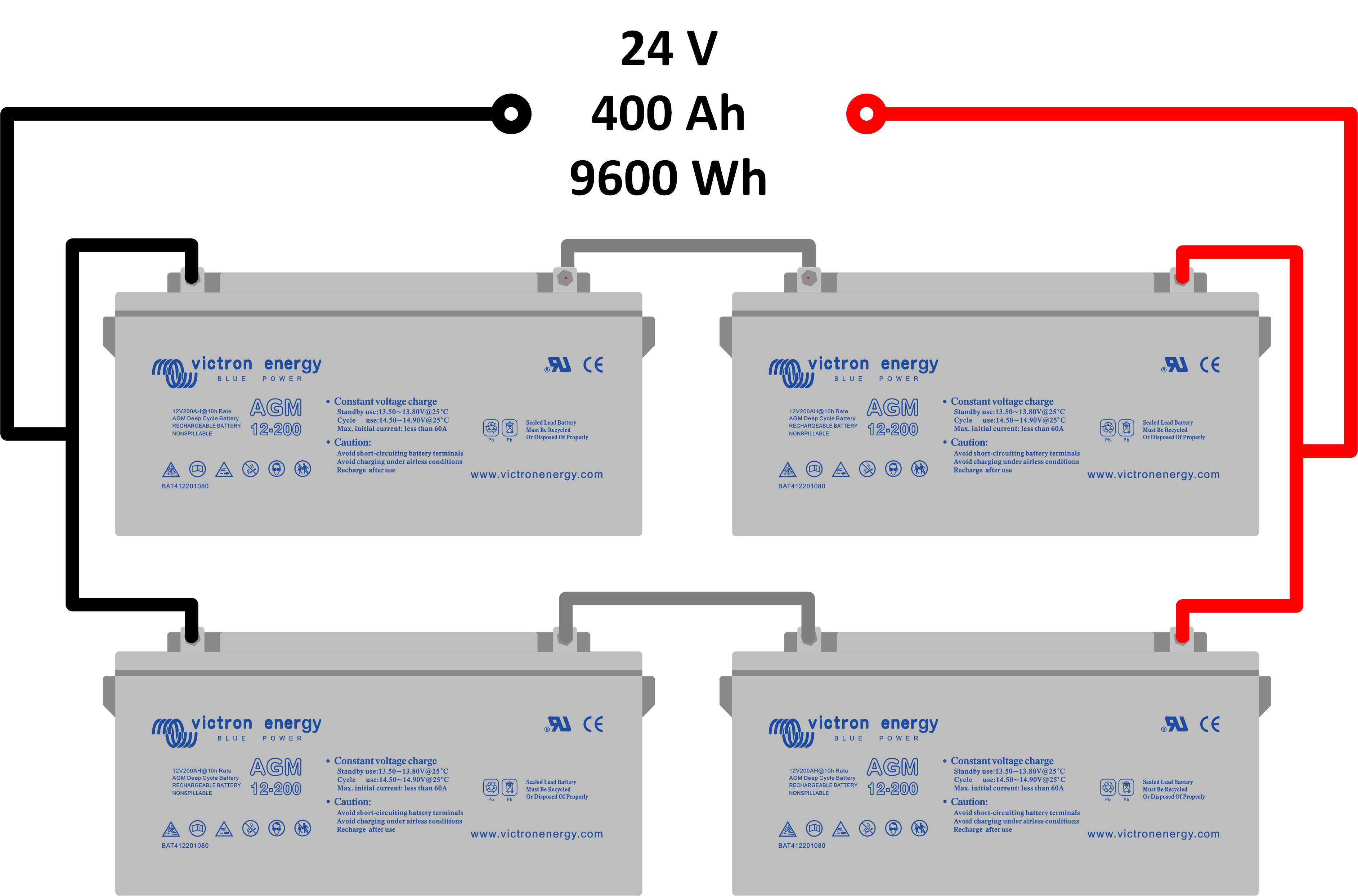
Four batteries in series/parallel. | ||
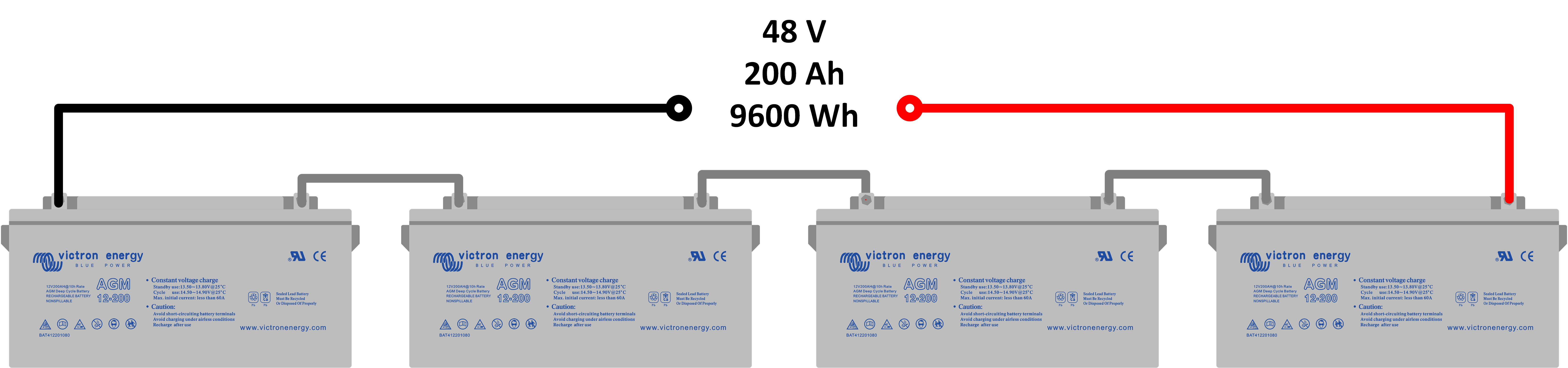
Four batteries in series. | |||
3.2. Large battery banks
If a large battery bank is needed, we do not recommend that you construct the battery bank out of numerous series/parallel 12V lead acid batteries. The maximum is at around 3 (or 4) paralleled strings. The reason for this is that with a large battery bank like this, it becomes tricky to create a balanced battery bank. In a large series/parallel battery bank, an imbalance is created because of wiring variations and slight differences in battery internal resistance. |
Examples of large battery banks containing 2V lead acid batteries or lithium batteries: | ||
2V lead acid batteries: 2V OPzV or OPzS batteries are available in a variety of large capacities. You only have to pick the capacity you want and connect them in series. They are supplied with dedicated connection links exactly for that purpose. 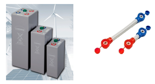 2V OPzV lead acid batteries and connection links. | 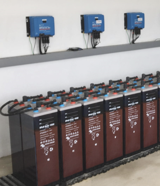 | |
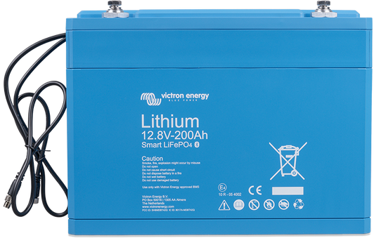
Victron Energy lithium Battery Smart: The lithium Battery Smart batteries have internal cell balancing and an external battery management system (BMS).
Lithium Battery 12,8V & 25,6V Smart | 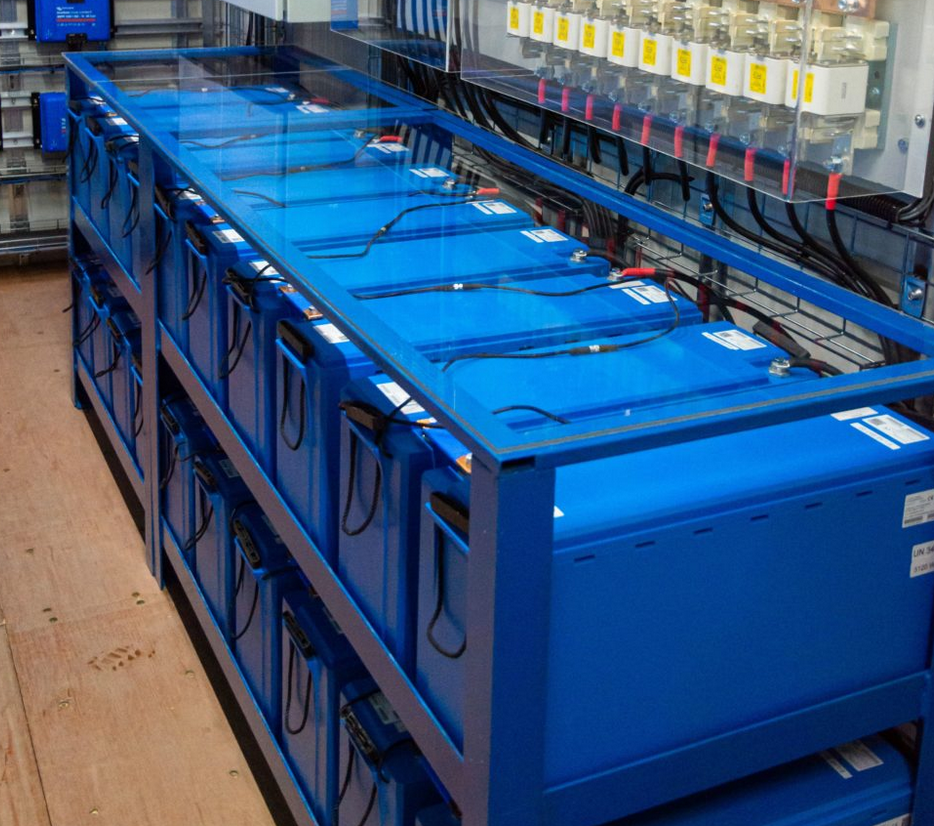 | |
Smart Lithium batteries: With cell balancing and internal or external battery management system (BMS). Each battery has the ability to communicate with each other, but they can also communicate with a monitoring device. In Victron’s case, this is a GX device. The batteries will generate a total state of charge value for the whole battery bank and send this to the GX device. For more information on which brands can work with Victron and how to set them up see this link: https://www.victronenergy.com/live/battery_compatibility:start. | 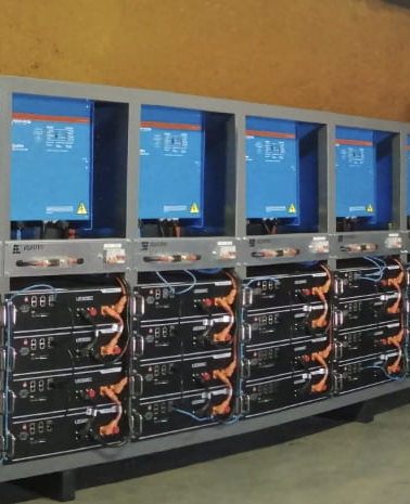 | |
Other battery chemistries: Flow batteries and other chemistries. These are commonly available in 48V. Multiple batteries can connect in parallel without any issues. Each battery has its own battery management system. Together they will generate a total state of charge value for the whole battery bank. A GX monitoring device is needed in the system. For more information on which brands can work with Victron and how to set them up see this link: https://www.victronenergy.com/live/battery_compatibility:start. | 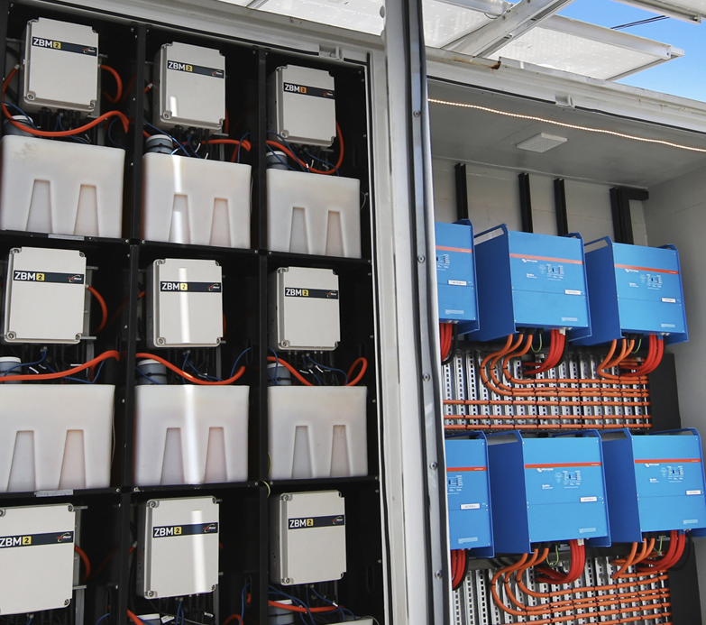 | |
3.3. Parallel battery bank wiring
Battery bank wiring matters It matters how a battery bank is wired into the system. When wiring a battery bank, it is easy to make a mistake. One of the most common mistakes is to parallel all the batteries together and then connect one side of the parallel battery bank to the electrical installation. As indicated in the image on the right. |
|
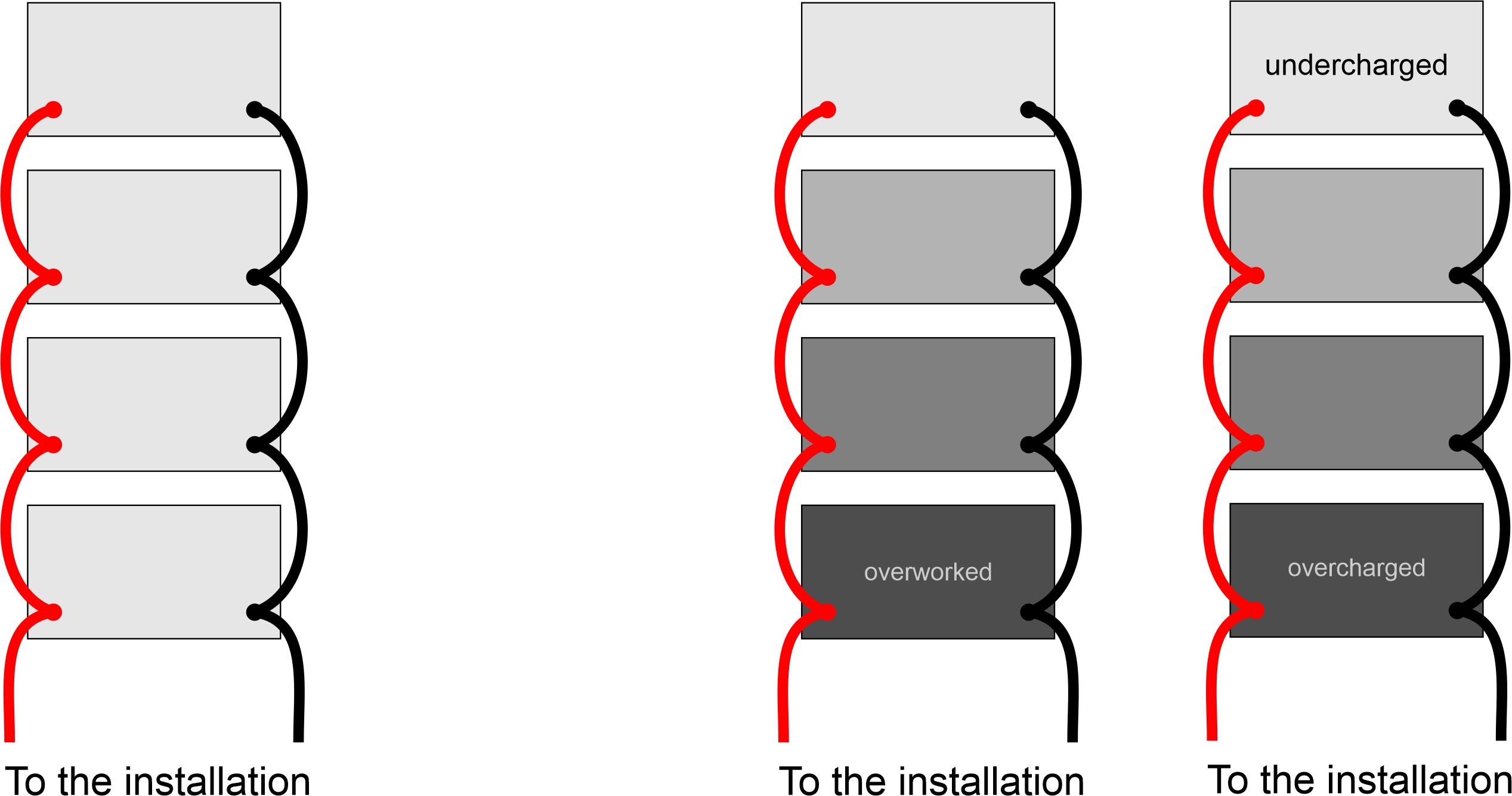
What happens when a load is connected? The power flow from the bottom battery only goes through the main connection leads. In contrast, the power from the subsequent batteries has to traverse the main connection and the additional interconnecting leads to reach the next battery. As the number of batteries increases, the number of interconnecting leads also increases. This results in a decrease in the current available from the top battery compared to the bottom battery. |
What happens if the battery bank is charged? The bottom battery gets charged with a higher current than the top battery. The top battery gets charged with a lower voltage than the bottom battery. The result is that the bottom battery is worked harder, discharged harder and charged harder. The bottom battery will fail prematurely. |
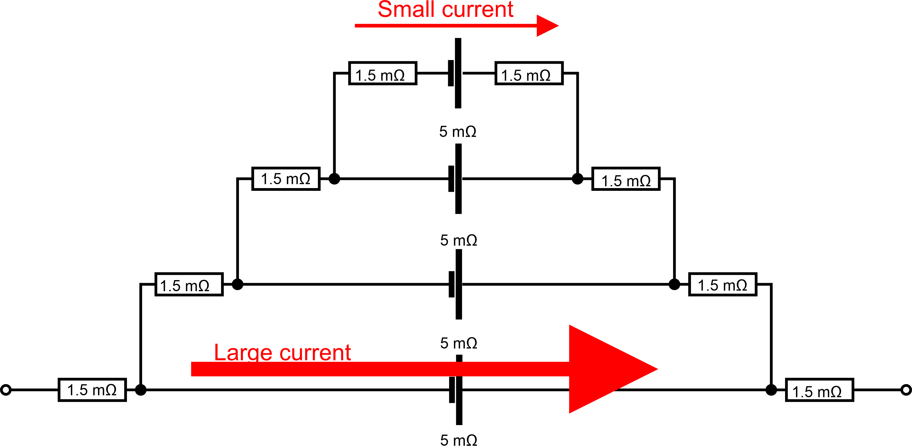
Why is cable resistance important when wiring battery banks? Remember that a cable is a resistor. The longer the cable, the higher the resistance. Also, the cable lugs and the battery connections will add to this resistance. To give an indication of this, the total resistance for a 20cm, 35m2 cable together with cable lugs attached is about 1.5mΩ. You might say that 1.5mΩ is not much but remember that the internal resistance of a battery is also low. Therefore, it does matter a lot! The internal resistance of a battery is typically between 10 to 3mΩ. If you construct an electrical diagram of an incorrectly wired battery bank it will look like this:
Current will always choose the path of least resistance. Most of the current will therefore travel through the bottom battery. And only a small amount of current will travel through the top battery. The correct way of connecting multiple batteries in parallel is to ensure that the total path of the current in and out of each battery is equal. |
There are four ways to correctly wire a parallel battery bank: | |
| 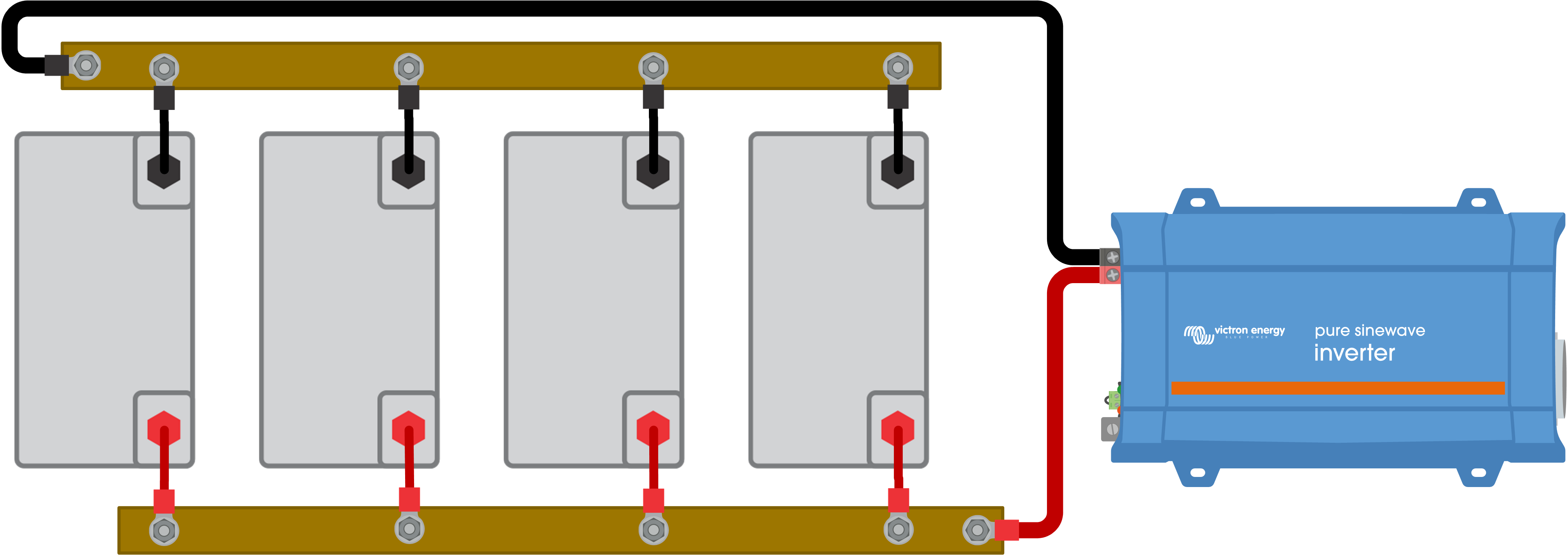 |
| 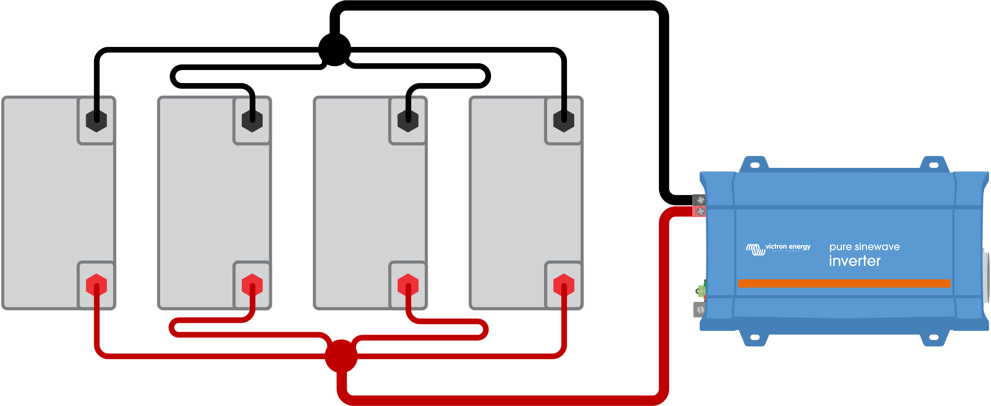 |
| 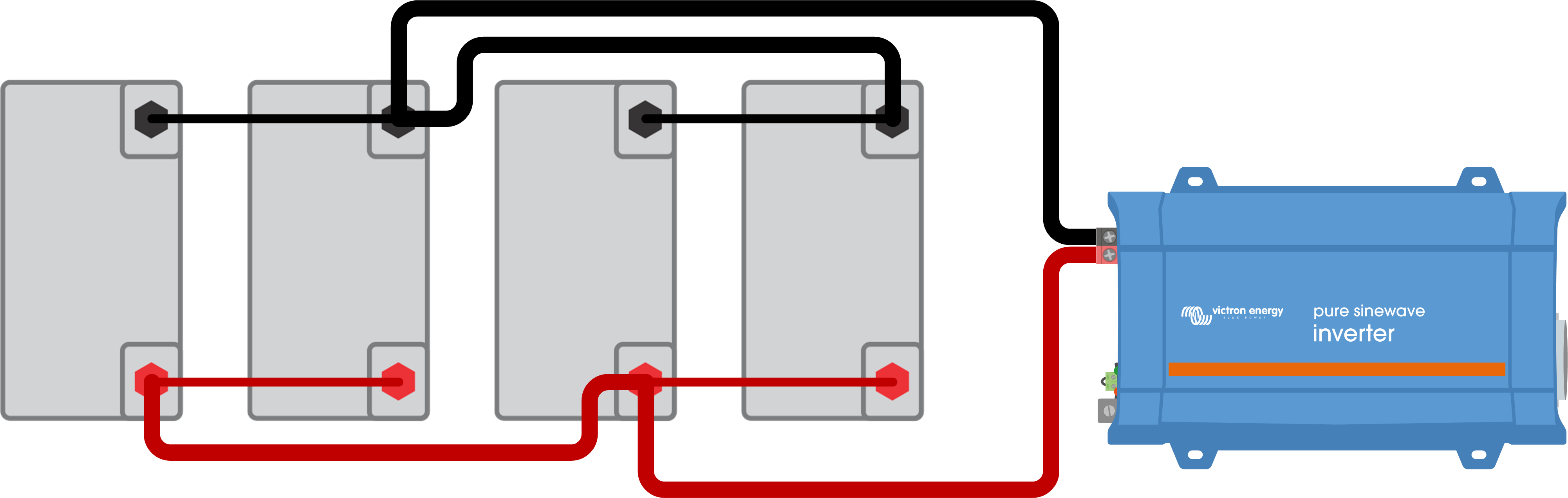 |
| 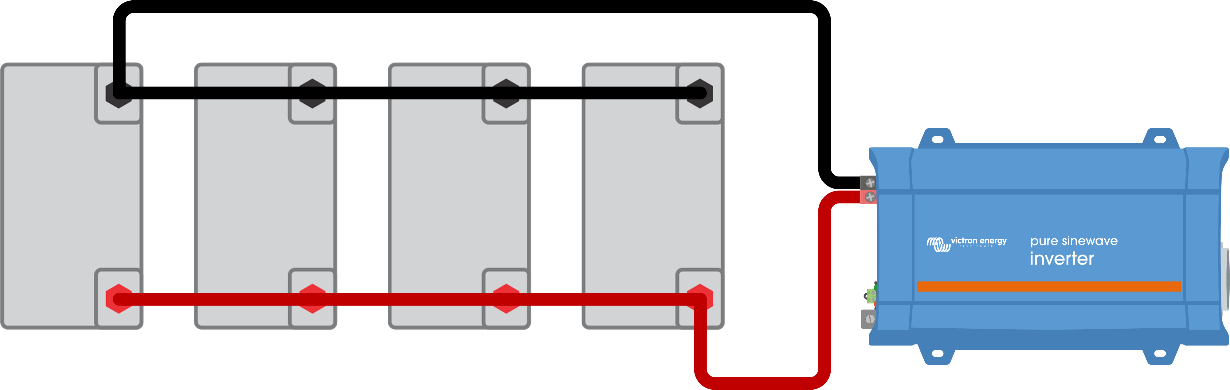 |
3.4. Lead-acid battery bank balancing
When creating a lead-acid battery bank with a higher voltage, like 24 or 48V you will need to connect multiple 12V batteries in series. But there is one problem with connecting batteries in series, and this is that batteries are not electrically identical. They have slight differences in internal resistance. So, when a series string of batteries is charged, this difference in resistance will cause a variance in terminal voltages on each battery. Their voltages become “unbalanced”. This “unbalance” will increase over time and will lead to one of the batteries being constantly overcharged while the other battery is constantly undercharged. This will result in a premature failure of one of the batteries in the series string. |
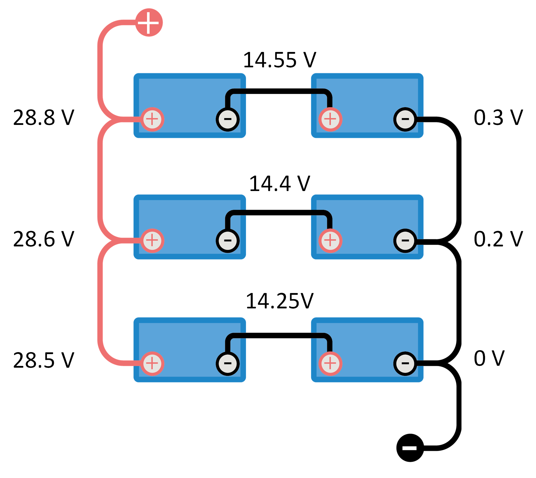
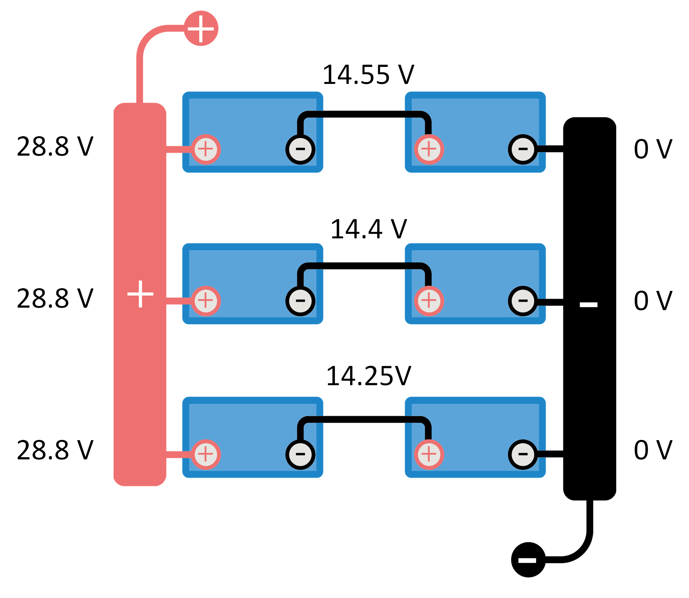
How to check if a battery bank is balanced: | |
| 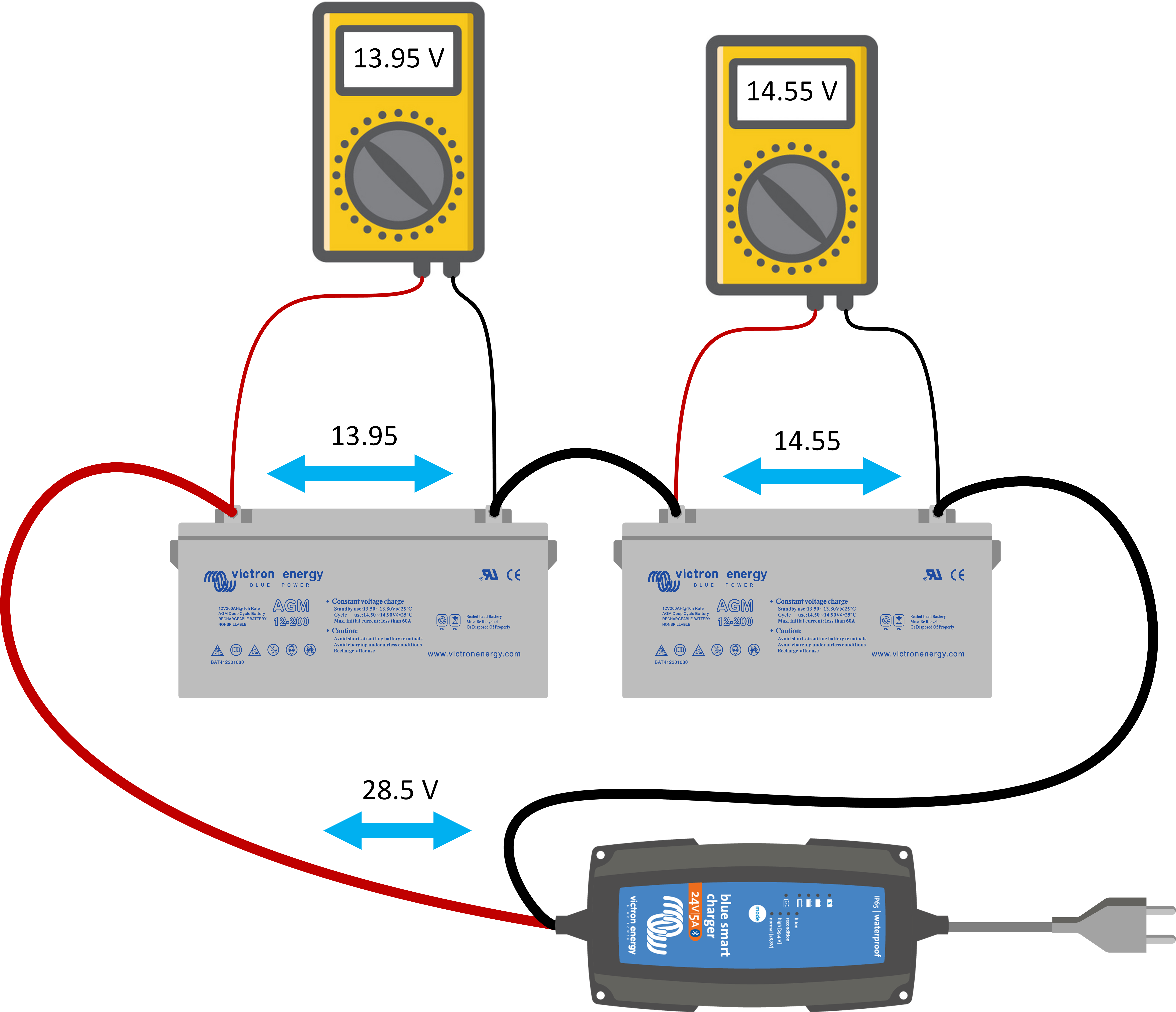 |
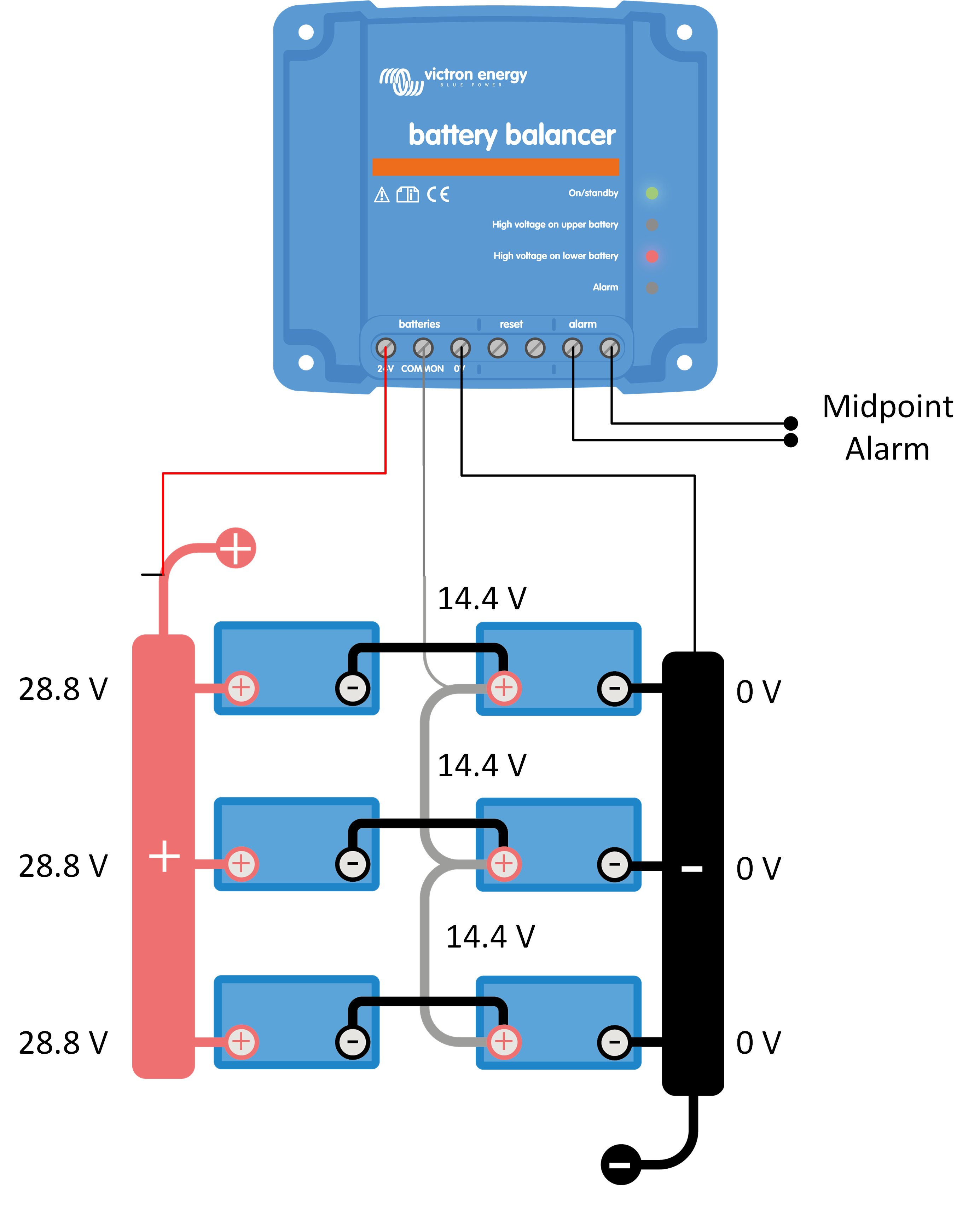
How to prevent battery unbalance on initial installation: To prevent initial battery unbalance, make sure you fully charge each individual battery prior to connecting them in series (and/or parallel). To prevent unbalance in the future, as the batteries are aging, use a Battery Balancer. The battery balancer is wired into a system as indicated in the image on the right. It measures the battery bank voltage and also the individual battery voltages. |
How the Battery Balancer works:
| 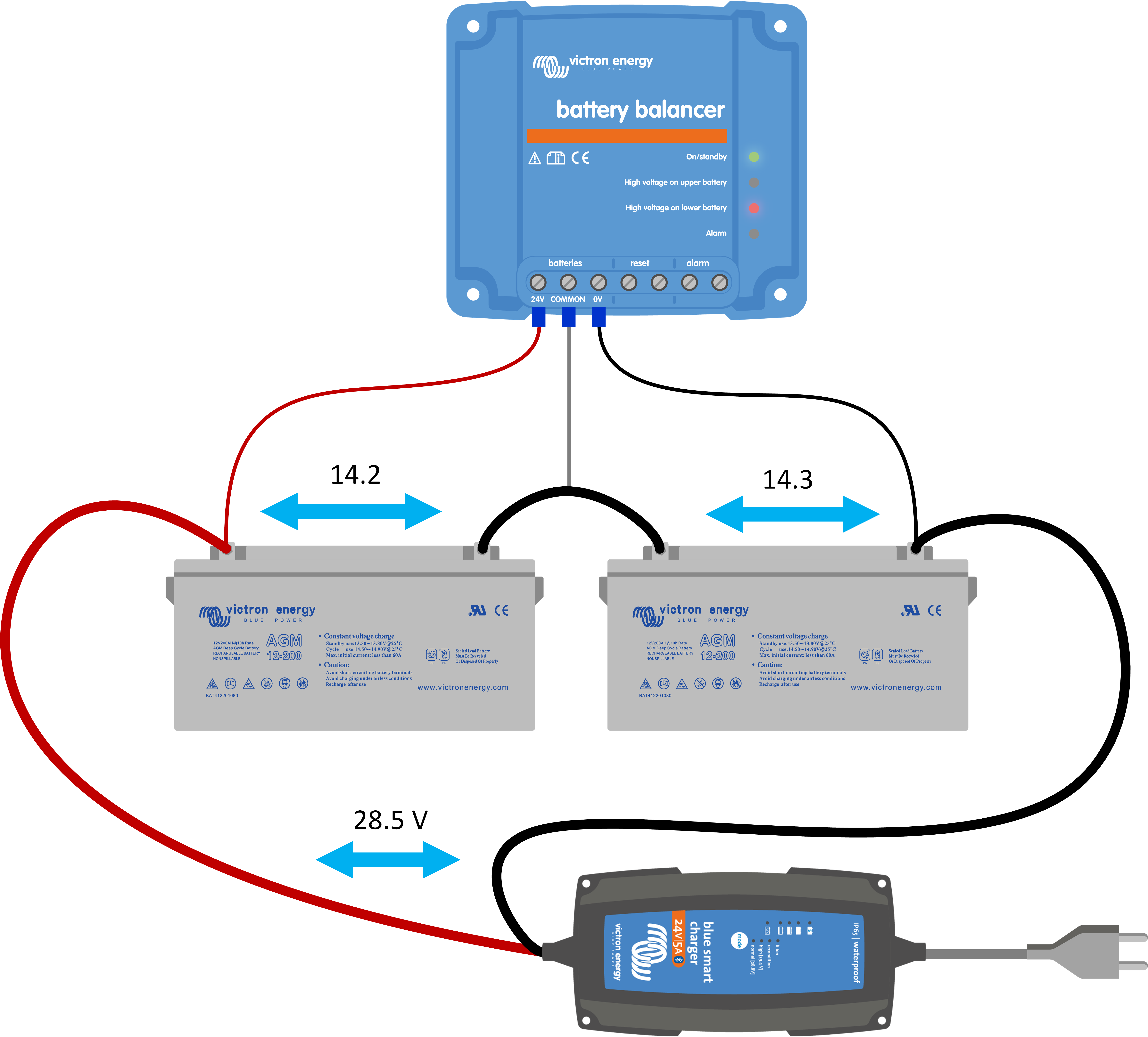 |
If battery balancing does not have the required effect and the voltage difference becomes larger than 0.2V, the battery unbalance is larger than the battery balance can correct. This is most likely an indication that one of the batteries has developed a fault and the Battery Balancer will sound an alarm and it will activate its alarm relay. For a 24V system, a single battery balancer is needed. And for a 48V system, three battery balancers are needed, one between each battery. For more information see the product information page of the Battery Balancer at: https://www.victronenergy.com/batteries/battery-balancer | |
3.5. Battery bank midpoint
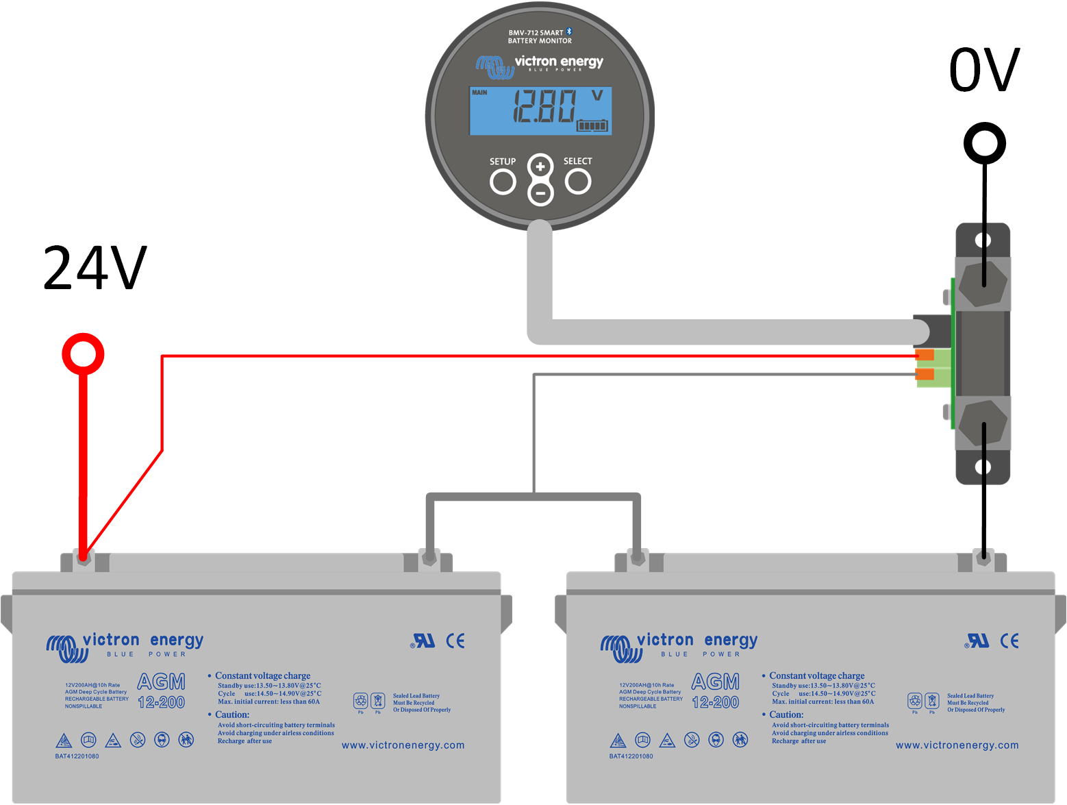
Battery unbalance can be detected by looking at the midpoint voltage of a battery bank. If the midpoint voltage is monitored, it can be used to generate an alarm when it deviates beyond a certain value. Both a battery balancer and a battery monitor can generate a midpoint alarm. The BMV 702, BMV 712 and SmartShunt battery monitors all have a second voltage input that can be used for midpoint monitoring. It can be wired to the midpoint of the battery bank. The battery monitor will display the difference between the two voltages or as a percentage. For more info see the battery monitor product page at: https://www.victronenergy.com/battery-monitors |
A midpoint alarm can mean the following:
|  |
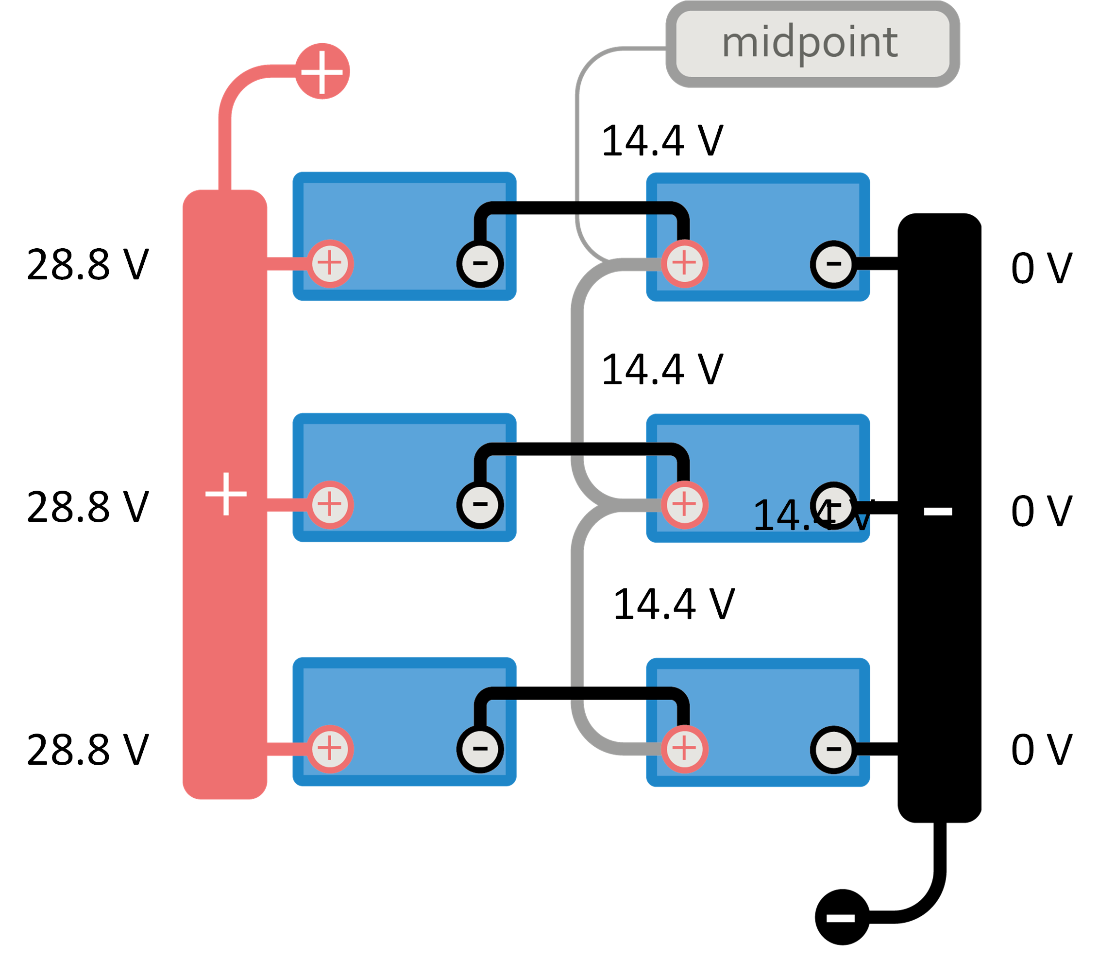
In a series/parallel battery bank it can be helpful to connect the midpoints of each parallel series string. The reason to do this is to eliminate unbalance within the battery bank. |
How to connect midpoints: | |
|  |
|  |
|  |
|  |
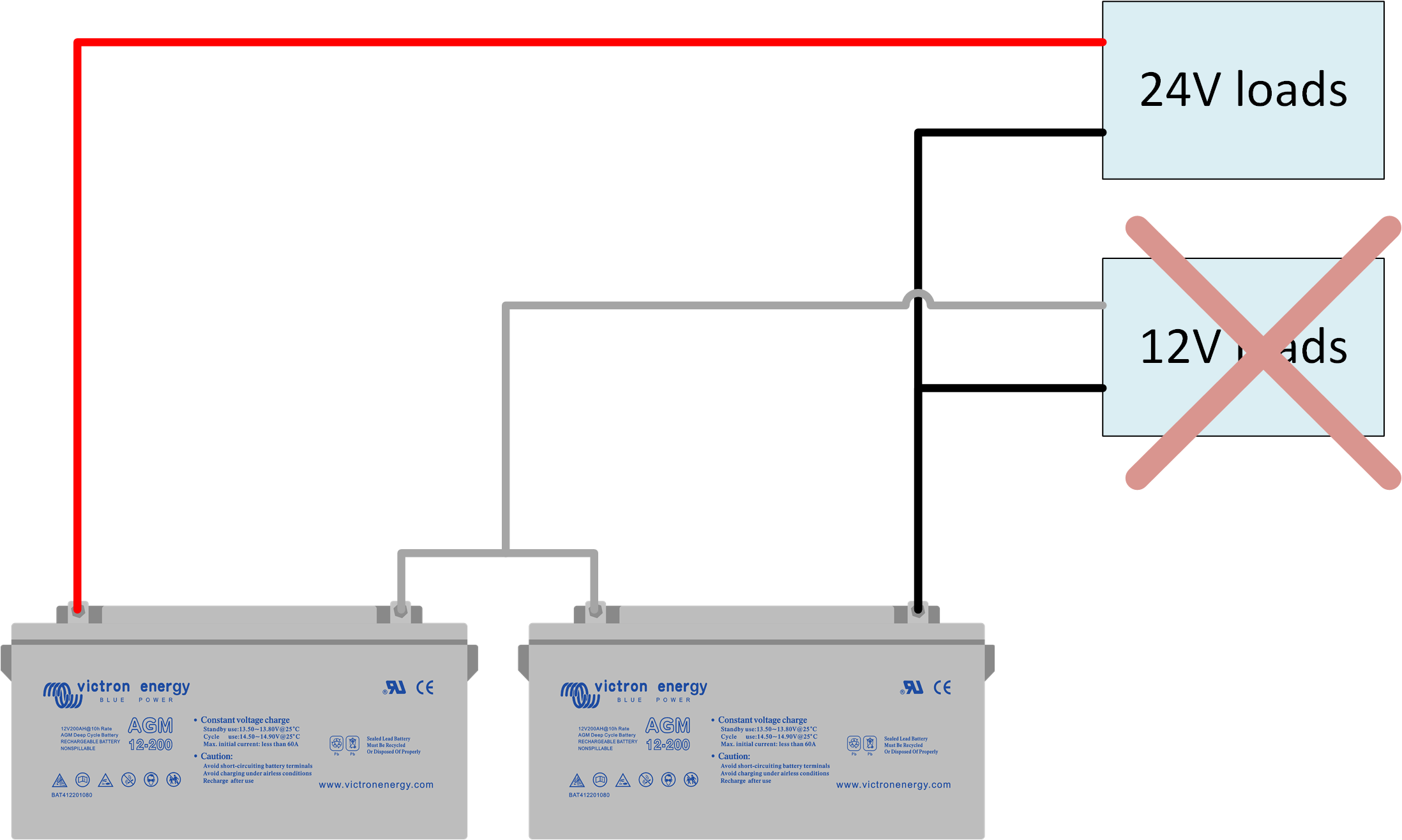
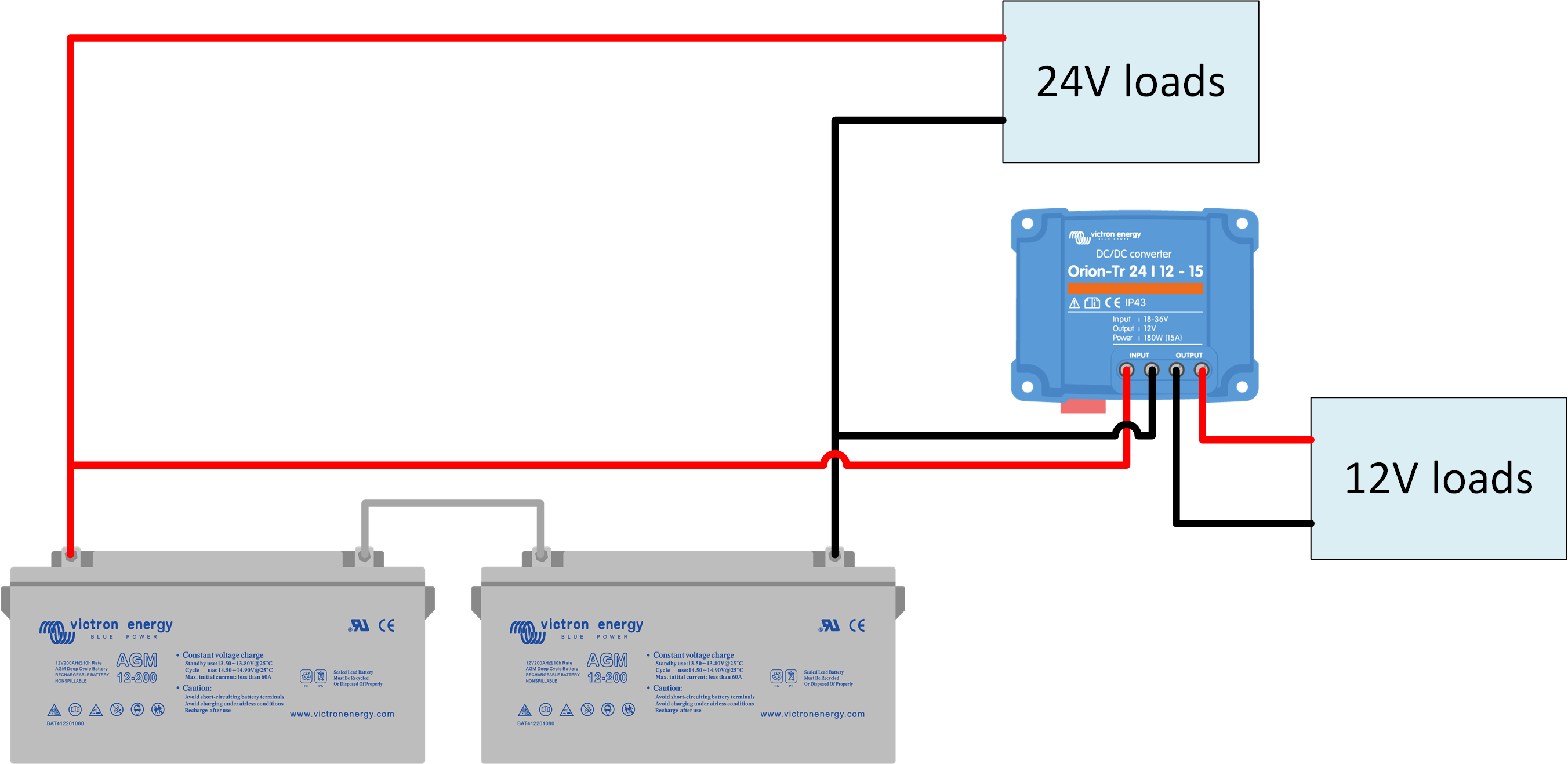
Do not connect loads to the midpoint of a battery: It is not recommended to connect loads to the midpoint of a battery bank in order to be able to run loads that require a lower voltage. Doing so will create a large imbalance in a battery bank. This imbalance is much bigger than a battery balancer can potentially rectify (larger than 0.7 A) and the battery that is used to provide the lower voltage will fail prematurely. The only reason to use the midpoints of a battery bank is for balancing and/or monitoring purposes. | |||
Do not do this: | But instead use an Orion DC-DC converter: | ||
|
| ||