6. AC wiring
This chapter covers AC electricity generation, distribution, cable sizing and the AC wiring of inverter/charger systems. |
6.1. Power generation
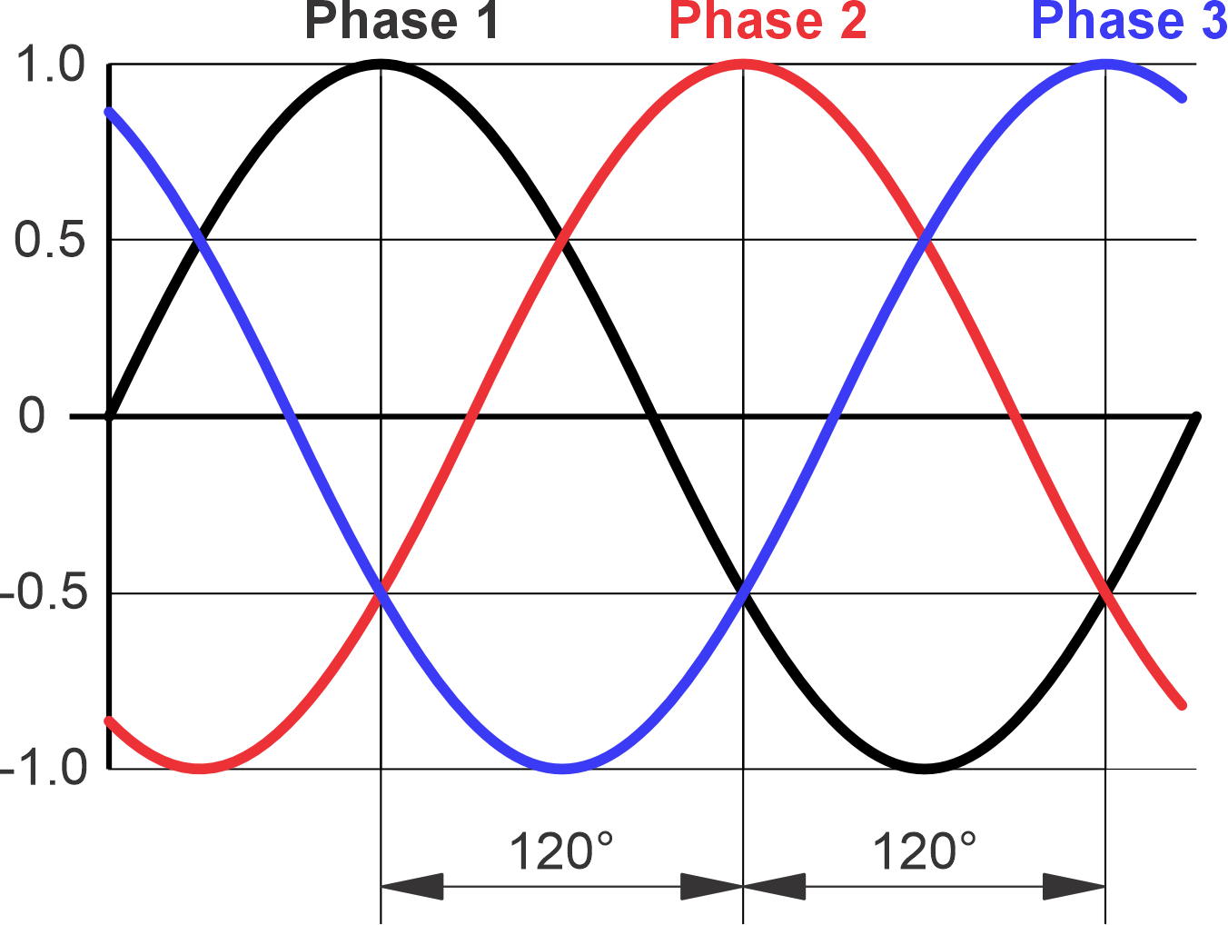
The generator in a power station generates 3-phase electricity. Each of these 3 phases has an alternating voltage of 230 Volt (or a different voltage, depending on the country). The voltage alternates at a frequency of 50 (or 60) Hz. And because the coils in the generator are rotating, there is a 120° phase shift between each phase. |
| |
The 3 coils are connected to each other and create a triple circuit, a so-called star configuration. A single coil (phase) has a potential of 230Vac. And a second potential level is created between two coils. Due to the 120° phase shift, the potential is 400Vac. To be able to use the phases separately the common point (star point) is connected to a conductor called “neutral”. Between the neutral and one of the phases a voltage of 230Vac exists. The Neutral conductor is a conductor that can be used by all 3 phases and can be used in 3 separate electrical circuits. | 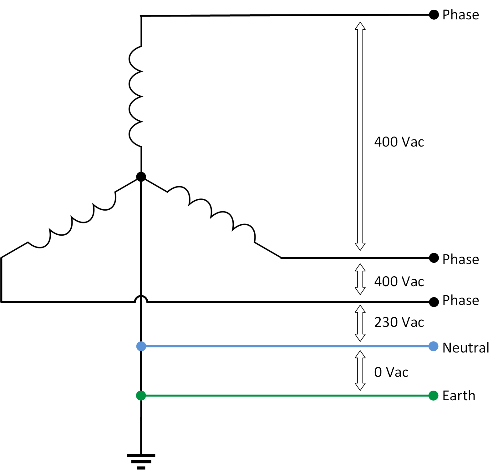 | |
The star point acts as a neutral in an electrical house installation. The function of the neutral conductor is to enable separate use of each phase and each phase can be used as an individual 230Vac supply. The neutral is also connected to a metal spike driven into the ground, the so-called earth spike. In this way, the potential of the earth equals 0 Volt. This connection is called earth. | ||
A 3-phase load, like a 3-phase electric motor, uses electricity from all 3 phases. The neutral does not have a function because the 3 electrical circuits will keep each other balanced. Only if one of the phases consumes more load than the others, the neutral will start to conduct current. This current is called the “compensating or equalizing current”. | 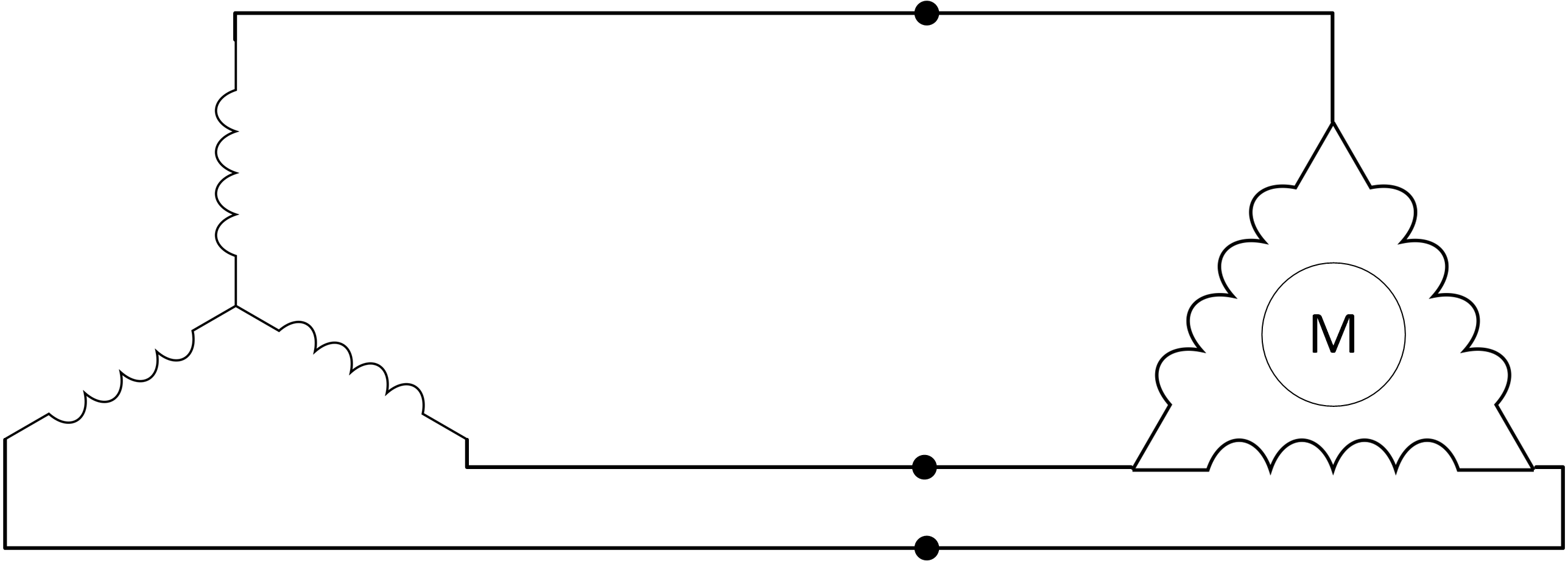 | |
When setting up 3-phase inverter/chargers they will need to be set up in a star configuration. They need to have a common neutral. Delta is not allowed. But the 3-phase inverter/charger system can power a “delta” configured load. Unequal loading is not an issue when the inverter/chargers are operating in inverting mode, but it might be an issue if they are operating in pass-through mode and are connected to a generator that is unable to deal with an unbalanced load. |
6.2. Distribution networks
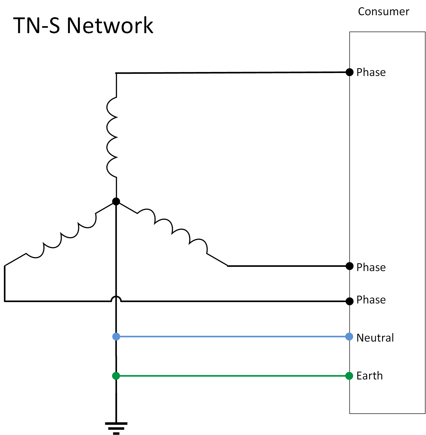
There are different ways in which power is distributed to the consumer. And different ways in how the consumer system is connected. All networks supply the 3 phases, but the way neutral and earth are bonded varies per network type. |
TN-S network
|  |
TN-C Network
| 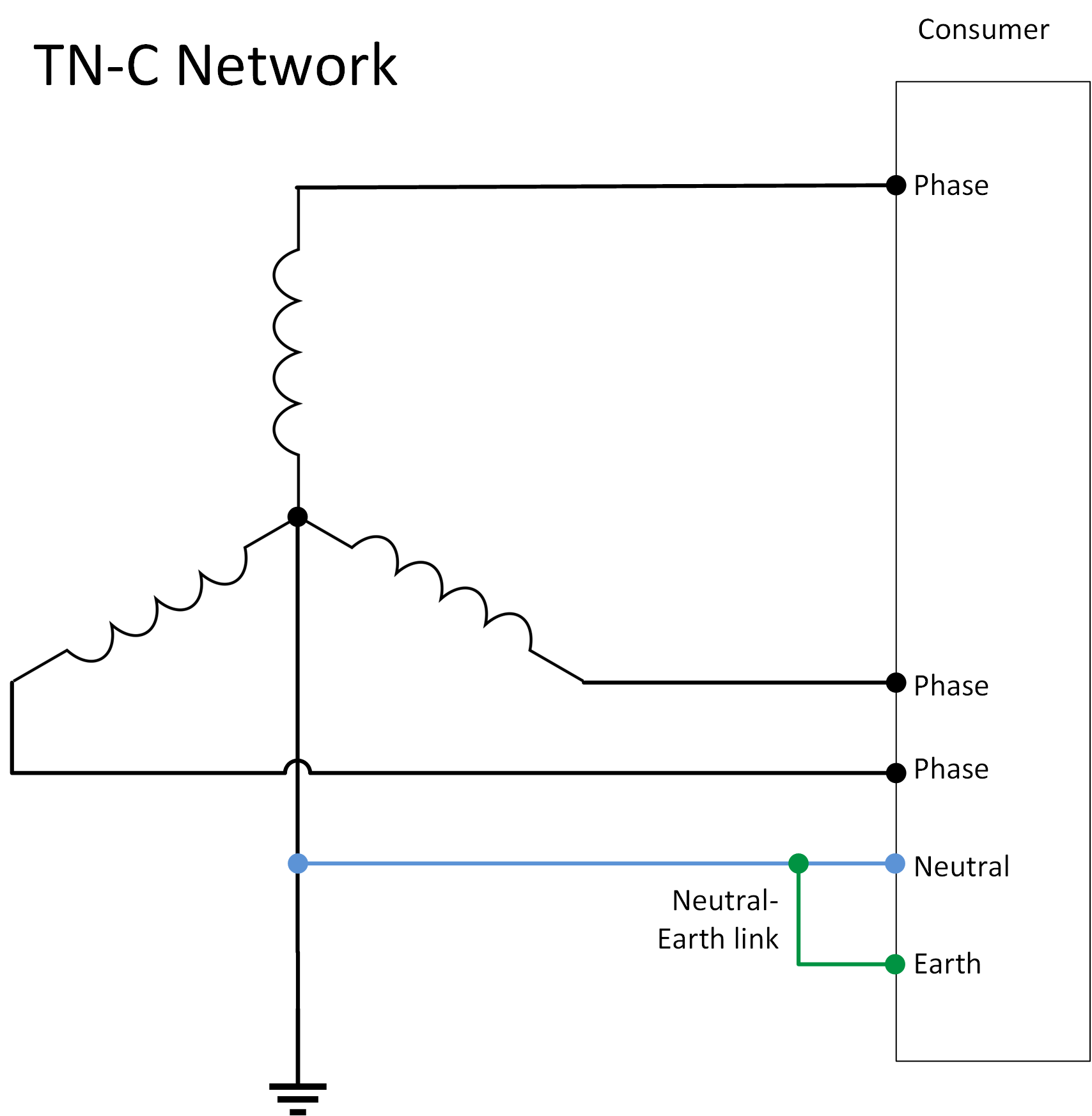 |
TN-C-S Network
| 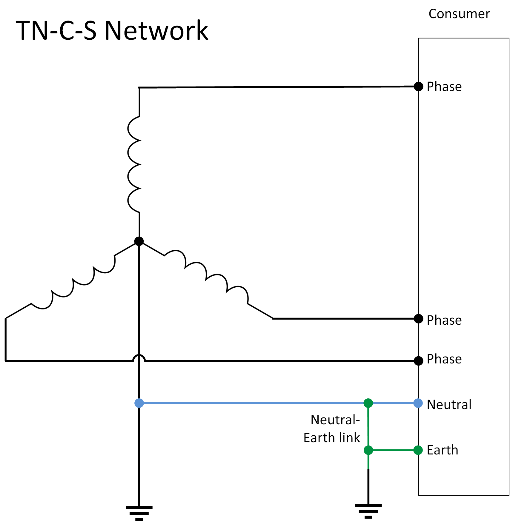 |
TT network
| 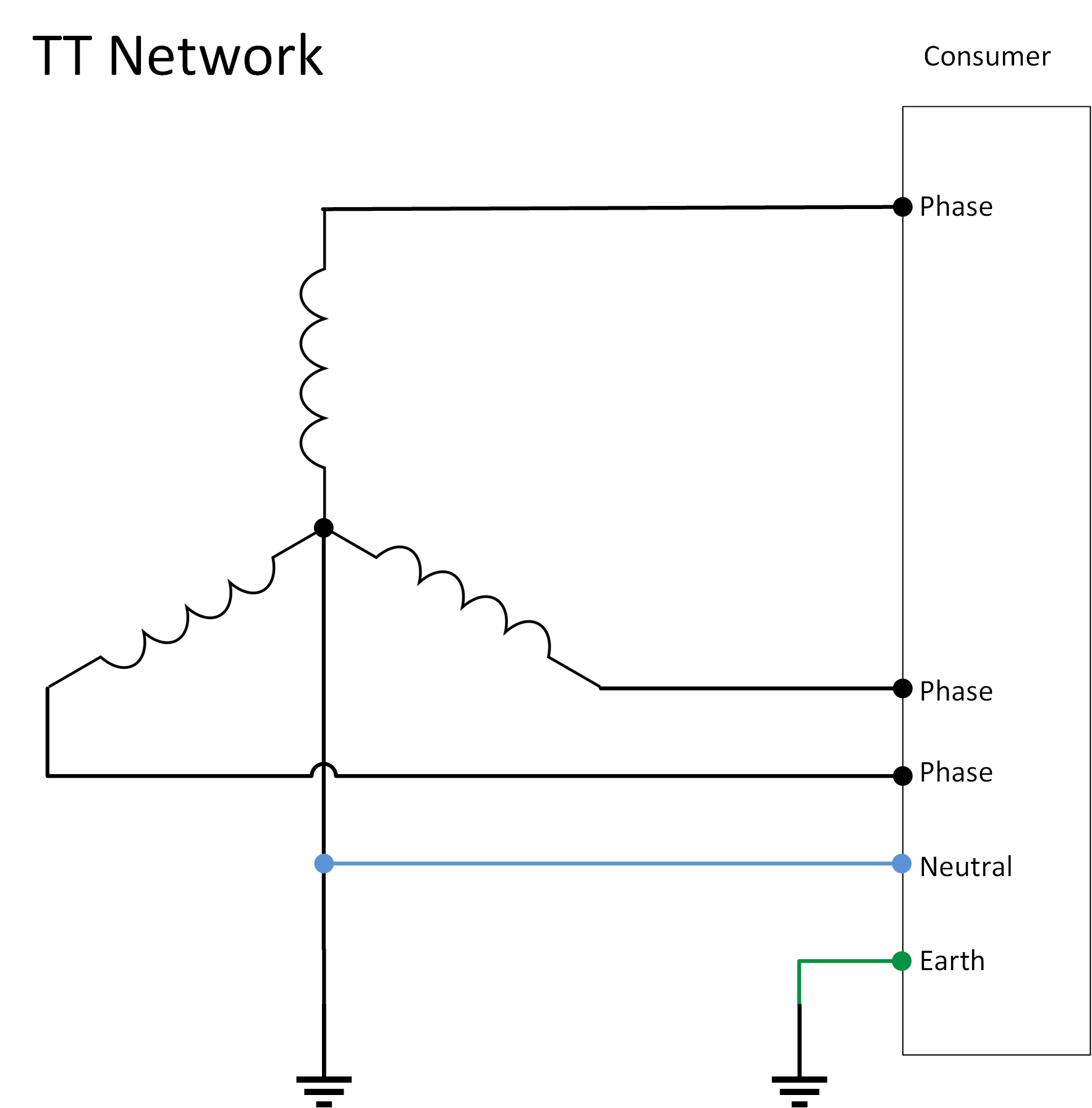 |
IT network
| 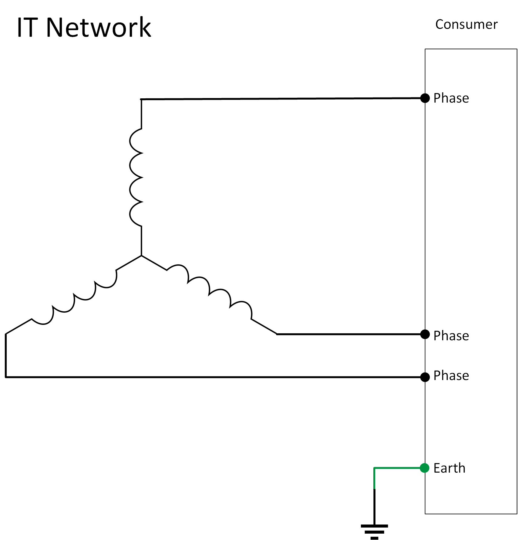 |
6.3. System current, VA and Watts
To be able to correctly calculate fuses, wiring size or inverter size, you will need to know how large the current in the AC circuit is. To be able to correctly calculate the current, there is one aspect of AC power that will need to be explained, namely Watt and VA. Like explained before, AC power is alternating power. Both the voltage and the current do not have a constant value like DC, but they alternate from positive, to negative, to positive and so on. This happens 50 times a second in a 50 Hz system and 60 times per second in a 60 Hz system. The waveform is a sine wave. |
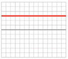 DC voltage | 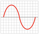 AC voltage |
Not only the voltage alternates in an AC circuit, the current also alternates. In a resistive system they alternate at the same time. However, if the circuit contains non-resistive loads, the current sine wave can lag behind the voltage sine wave, or be in front of the voltage sine wave. The three different types of loads are:
|
Below images depict the behaviour of the voltage (red) and current (blue) in an AC circuit with different types of loads: | ||
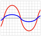 1: Resistive load, active, the current and voltage are in phase | 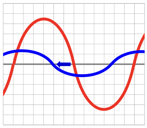 2: Inductive load - reactive passive, the current lags behind the voltage | 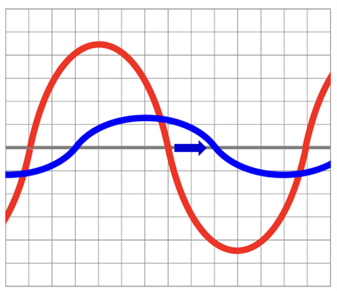 3: Capacitive load - reactive passive, the voltage lags behind the current |
Watt is the real power drawn by the equipment. The power rating in Watt determines the actual power purchased from the utility company, the diesel consumed by a generator or the heat loading generated by the equipment. VA is the “apparent power” and is the product of the voltage times the current drawn by the equipment. The VA rating is used for sizing wiring, circuit breakers, inverters or generators. In a purely resistive AC circuit, voltage and current waves are in step (or in phase) with each other. To calculate the current, this formula can be used:
|

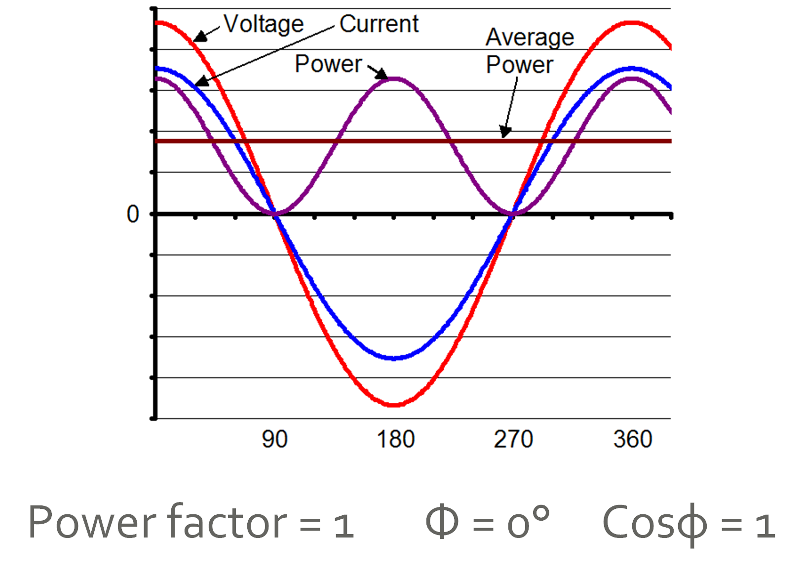
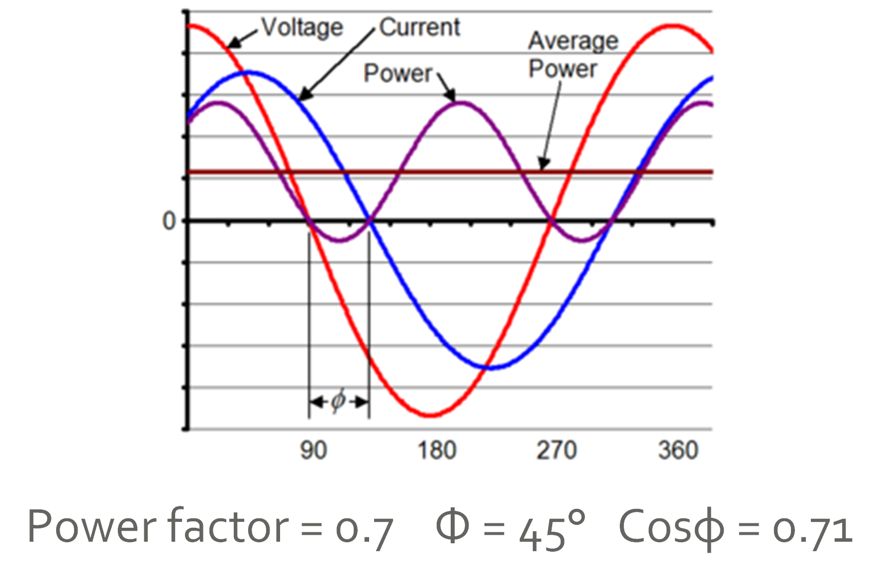
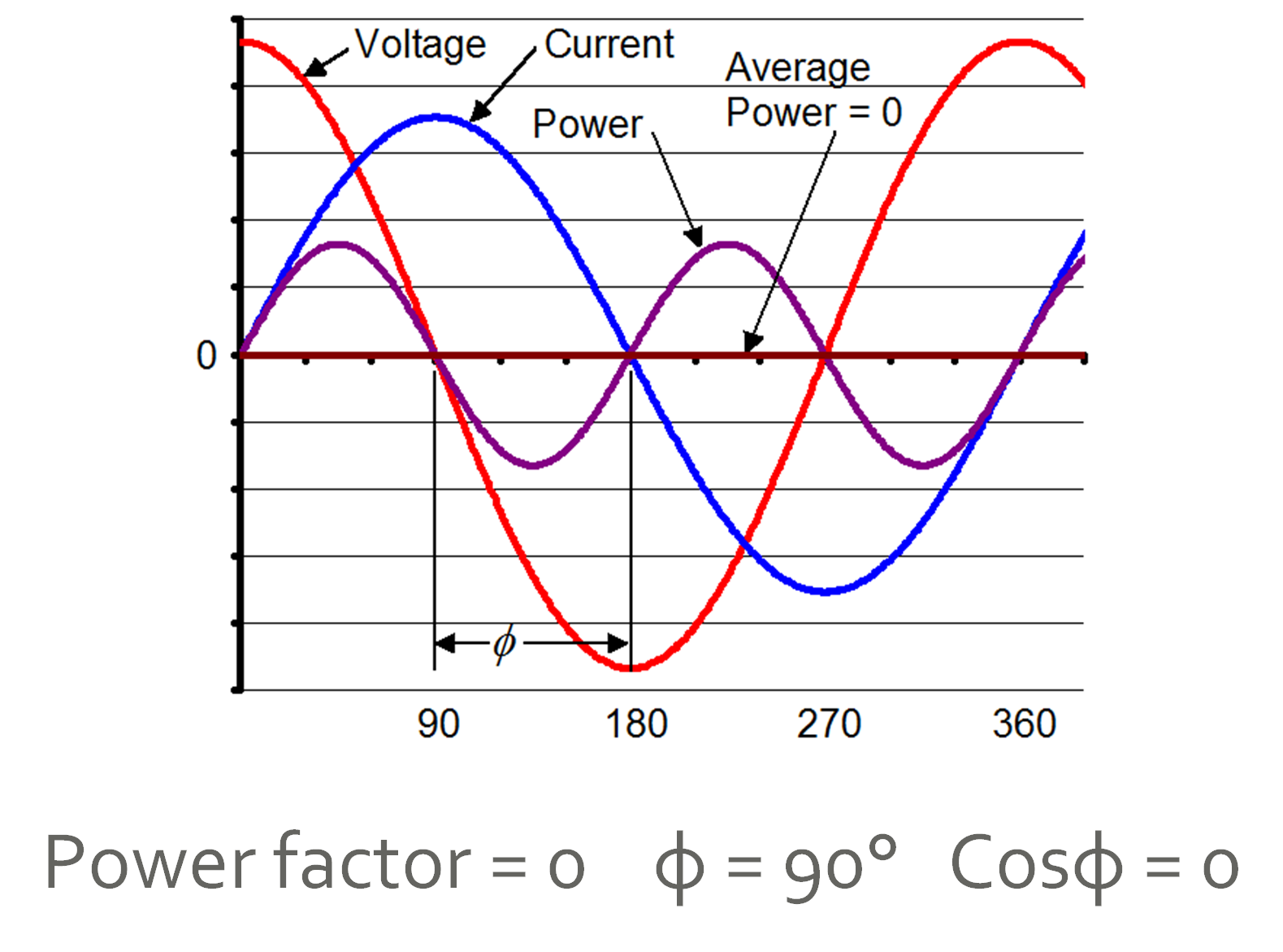
The power factor is 1 in a purely resistive system. When an AC circuit contains loads such as inductors or capacitors, a phase shift will occur between the current and voltage waves. Both these waves are not in step (in phase) anymore. Looking at the waves, if you calculate the power you will see that the True power (W) is less than the apparent power (VA). |
Power factor = 1 |
Power factor = 0.7 |
Power factor = 0 |
When the power factor is known the apparent power can be calculated.
On average a residential AC circuit has an average power factor of 0.8. So, for general calculations, it is okay to use 0.8 as the power factor. |

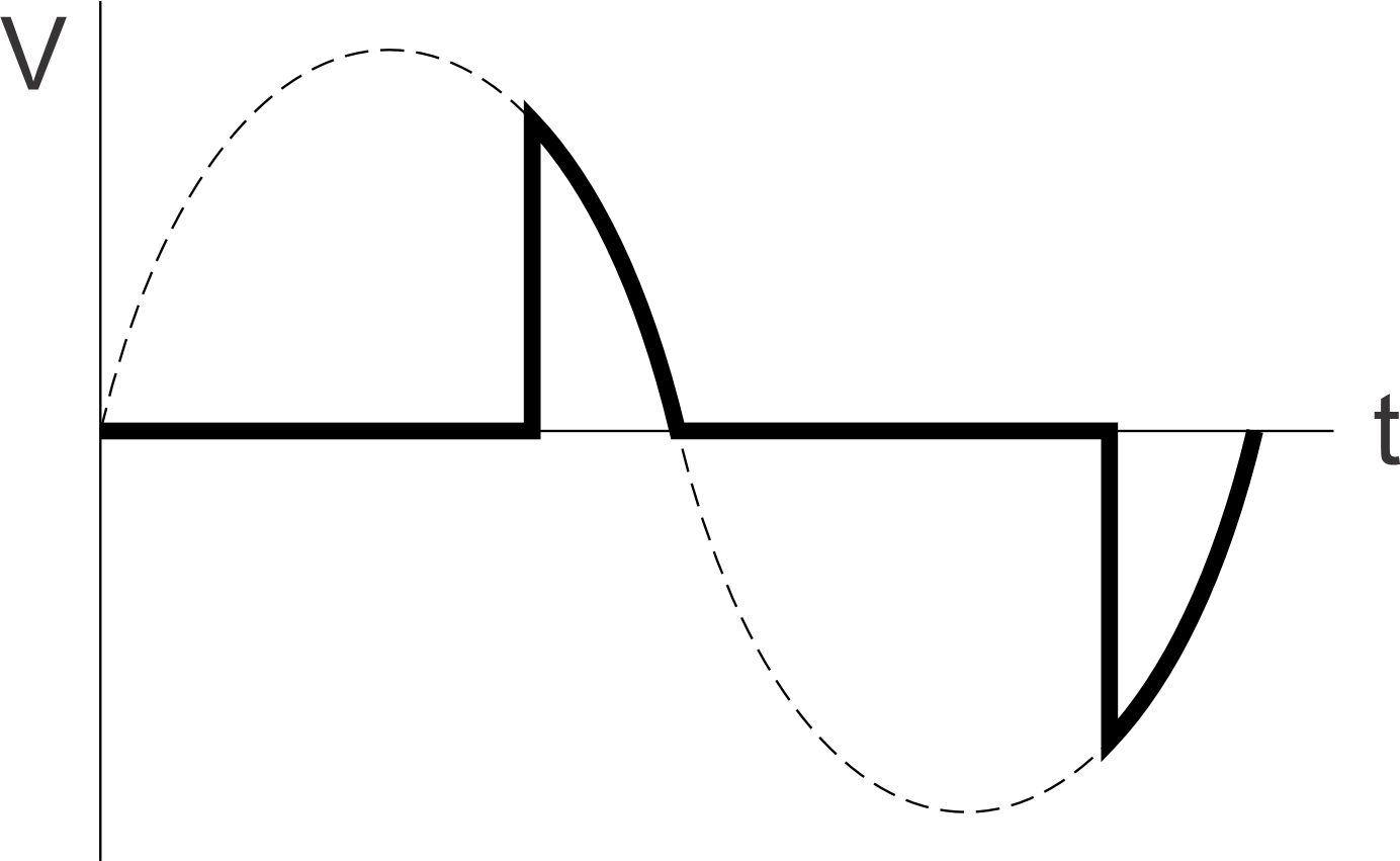
Non-Linear loads: Then there is one more type of load, the non-linear load. To put it simply, these are loads that do not load up the whole sine wave equally, or they might only use a part of the wave. The current drawn by the non-linear load will not have a sine wave shape, although the load is connected to a sine wave voltage.
Example of a non-linear load. Only part of the voltage is applied to the load. These often are loads that contain semiconductors, like diodes, thyristors or LEDs. Examples of these are AC LED lighting, light dimmers, heat guns, recitfiers and certain soft start devices. When an inverter powers a non-linear load, it may experience an overload situation sooner than expected based on the power rating of the load and the inverter. |
6.4. AC cabling
In a house or factory installation, the incoming electricity is divided into groups, usually on a distribution board. The diameter of the electrical wiring for each AC circuit (group) must be matched to the size of the expected maximum current in that circuit. This is to protect the connected loads and the electrical wiring. Voltage drop and heating of cables can also occur in AC circuits. Voltage drops can damage the connected appliance and cause heating up of cables, and in extreme cases, can lead to house fires. It is also essential to make good cable connections. Bad cable connections can also lead to voltage drop and heating. Use the guidelines as already described earlier. |
Do not use rigid AC wires: Avoid connecting the inverter/charger to wires with rigid strands (as shown in the image on the right). Wires with rigid strands are not suitable for the inverter/charger AC connectors, leading to poor contact and the risk of disconnection. Use wires with fine and flexible strands instead. | 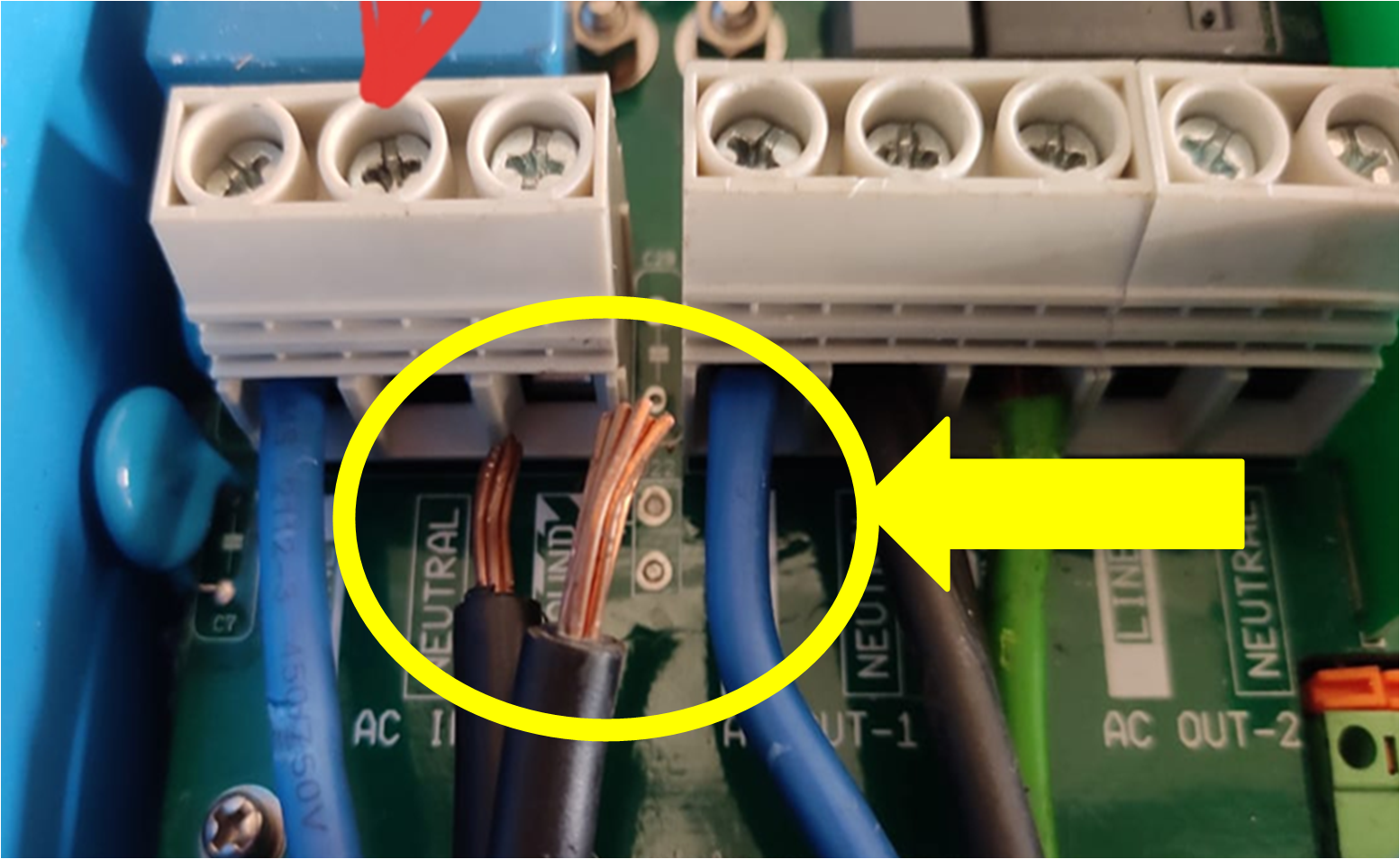 Rigid AC wires that have come loose. |
Wiring sizing: The Victron Energy Toolkit app also has a provision for calculating AC wiring for 120, 240 and 400Vac systems. When using the app, the aim is to select a wire size so that the voltage drop stays below 2.5%. For wiring calculations, you can use similar calculations as for DC wiring, as already explained. But be aware that the earlier mentioned rule of thumb cannot be used. For wiring for voltages from 200 to 400Vac, use this rule of thumb:
CautionPlease be aware that the "rule of thumb" might not meet your local AC wiring standards. It is meant to be used as a guide only. |
6.5. AC fuses and circuit breakers
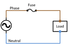
Fuses are generally located on the distribution board. Each AC circuit (group) is fused separately. The fuse is matched to the size of the expected load and to the cabling thickness. |
The fuse protects against:
|  |
Traditionally, a fuse contains a wire that melts when an unacceptable current passes through it. As soon as the wire in the fuse has melted the electrical circuit has been broken and no additional current will flow. More commonly automatic circuit breakers are used to protect against overcurrent. These are called Miniature Circuit Breaker (MCB). This device has two triggers for activating its switch-off mechanism. A thermal trigger for long-term small overload currents, and a magnetic trigger for large short duration currents like short circuit currents. |
MCBs come in three types: B, C and D. They all have the same thermal characteristics. But they have different short circuit current levels.
When a short circuit current occurs, with sufficient current, the MCB (B, C or D) is switched off within 100ms. | 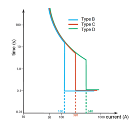 |
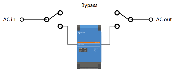
6.6. AC bypass switch
It is recommended to add a manual bypass to an inverter/charger system. This is especially useful in mission-critical systems. This will allow you to bypass the inverter/charger and connect the AC input (grid or generator) directly to the loads. It will prove invaluable in case the inverter/charger needs a configuration change or should anything go wrong with the inverter/charger and directly connect the AC input (grid or generator), if it needs to be removed for service.
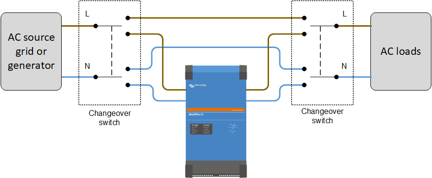
The functionality of a bypass switch. To create the bypass, the AC paths to and from the inverter/charger needs to be interrupted, and a separate bypass circuit needs to be established. The bypass needs to be rated to the full AC load of the system. The manual bypass can be constructed using two changeover switches. An example of a suitable changeover switch is the Hager SF263 2 pole changeover switch with a centre-off position. The below diagrams show how the changeover switches are wired in the system and the 3 switching possibilities.
The inverter/charger is connected and the bypass is disconnected.
The inverter/charger and the bypass are both disconnected.
The inverter/charger is disconnected and the bypass is connected. |


In case a low-power inverter/charger is used, like the MultiPlus Compact or the Multiplus 500 to 2000VA, it is easy to manually bypass the inverter/charger. Simply pull the black AC in and AC out plugs out of the inverter/charger and insert these plugs into each other. | 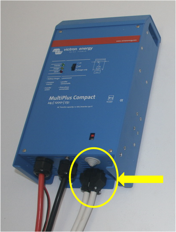 MultiPlus Compact AC plugs |
6.7. Special considerations AC wiring parallel inverter/charger systems
Multiple inverter/chargers can be connected in parallel to create a larger inverter/charger. When connecting a parallel system to an AC supply it matters what length and thickness the AC wires have. Unlike DC cabling, for AC cabling it is important to not make the cables too short or too thick. Do not over-dimension the AC cabling. Using extra-thick cabling has negative side effects. In a parallel system, each inverter/charger should be identical. Hovever, this is not always the case. Each inverter/charger contains an internal AC input contactor. These contactors are not always completely identical, they can have a small difference in their internal resistance, compared to the other contactors. This small resistance difference might result in the AC current being diverted from one unit to another. | 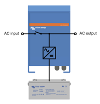 Example of the internal wiring of an inverter/charger. |
In a parallel system, the AC current should be evenly distributed through all paralleled inverter/charger units. When the resistance in the cabling is very low, the small difference in contactor resistance will result in a large relative difference. And this will cause unequal current distribution. |
An exaggerated example: | |
Unit A and unit B are connected in parallel. Extremely thick and short cabling is used so that a very low wiring resistance was created. But, the two units have a slight internal (AC contactor) resistance. See the image on the right. In this scenario, the total resistance for unit A is 0.1mΩ and the total resistance for unit B is 0.2mΩ. This will result in Unit A carrying twice as much current as Unit B. | 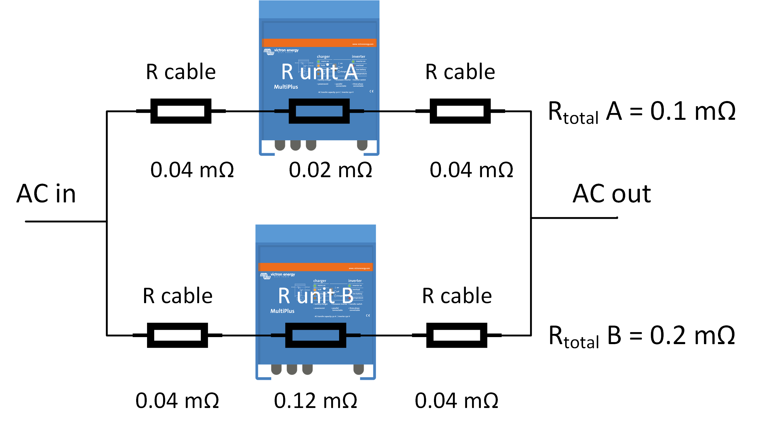 |
Now, we use the same 2 units in parallel, but we use thinner and longer cables. See the image on the right. The total resistance for unit A is 1.5Ω and the total resistance for unit B is 1.6 Ω. This will result in a much better current distribution. Unit A will carry only 1.066 times more current than unit B. | 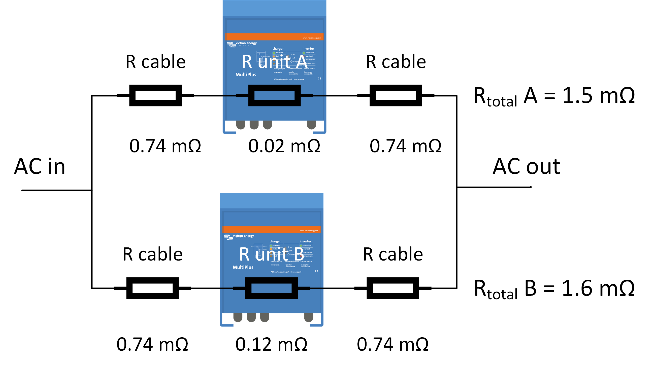 |
Preventing uneven distribution of AC currents: To safeguard against this issue, it is recommended to use long AC cables, of similar length. Always follow the recommended cable lengths and thicknesses as listed in the product manual. Do not increase the cross-section of the AC cabling more than is recommended in the manual! For example: The voltage drop tolerance of a 100A backfeed contactor is about 20mV at 100 A. Therefore, the total cable resistance (input + output) should be larger than R = 60mV/100A = 0.6mΩ. |
Checking for even distribution of AC currents: The best way to check if this type of wiring issue is affecting a parallel system is the following:
The current readings should be very similar. If there are big differences, then there is an issue with wiring (or with a connection). | 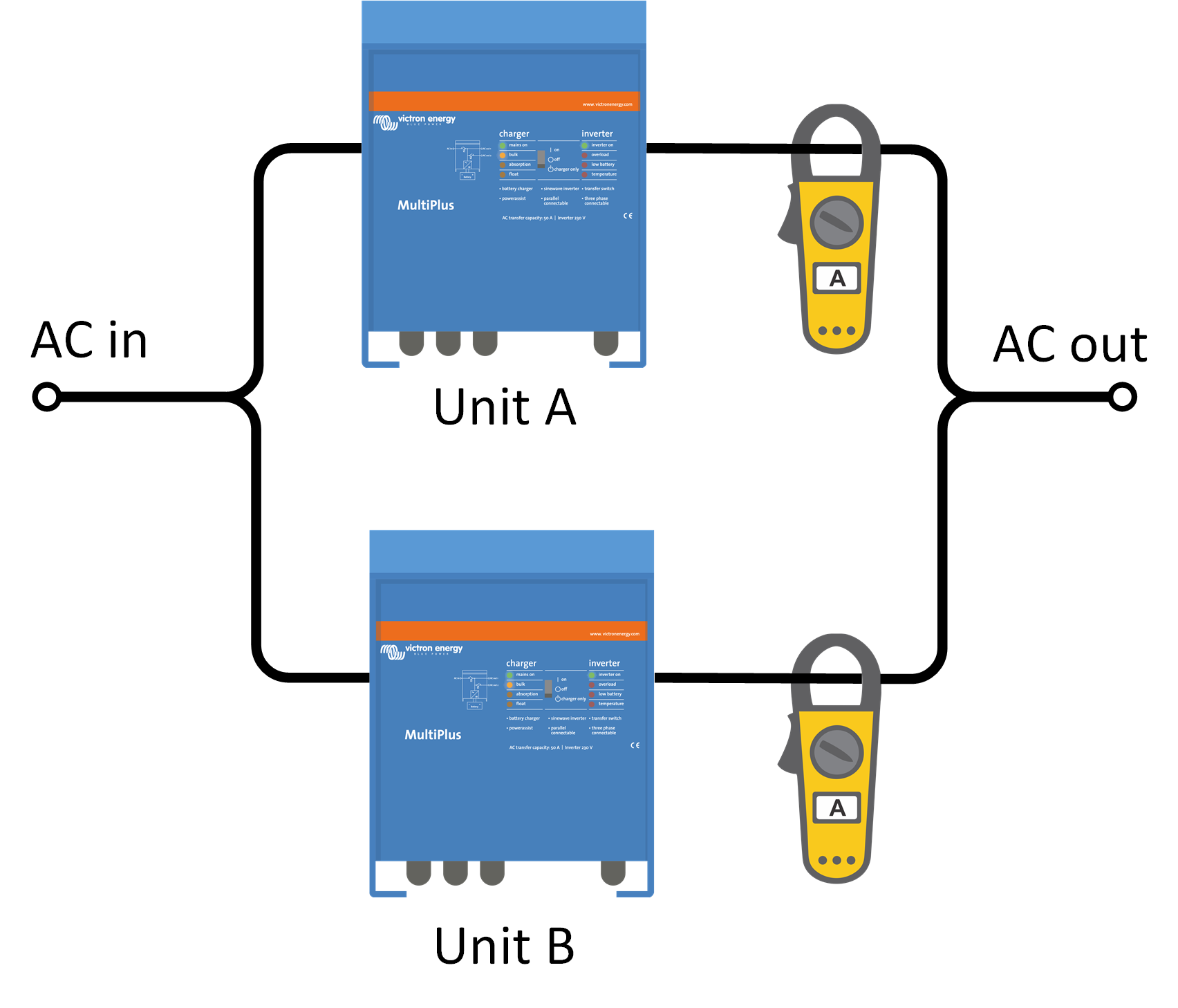 |
AC fusing parallel strings: Each unit needs to be fused individually. Make sure to use the same type of fuse on each unit due to the same resistance. Consider using mechanically connected fuses |
More information: For more info on parallel and 3 phase systems please read the Parallel and 3-phase manual, see https://www.victronenergy.com/live/ve.bus:manual_parallel_and_three_phase_systems |
6.8. Phase rotation 3-phase inverter/charger systems
Phase rotation: The 3 phases L1, L2 and L3 of a 3-phase supply need to be connected in numerological order. Pay special attention to the phase rotation of the AC supply from the grid or from a generator. When wired in the wrong rotation, the system will not accept the mains input and will only operate in inverter mode. In that case swap two phases to correct it. A quick way to fix phase rotation is to swap 2 random phases and see if now the inverter system will accept AC in. In case the system is mobile it is likely that, at some point, there will be a generator or grid connection with incorrectly wired phase rotation and the inverter/charger system will reject the input and stay in inverter mode, consequently draining the batteries. Mounting a simple changeover switch that can swap two of the phases is a nice solution that instantly fixes the phase-rotation issue, without stalling the event. Besides manual switching, there are also automatic devices available to do this. For more info on parallel and 3 phase systems please read the Parallel and 3-phase manual, see https://www.victronenergy.com/live/ve.bus:manual_parallel_and_three_phase_systems |