4. DC wiring
It is important to use the correct cable thickness in a system. This chapter explains why and contains other useful information on what to look out for when designing a system's DC wiring. |
4.1. Cable selection
The correct cable can only be selected once you know the currents in a system. To find out how to calculate the current see the Current, cable resistance and voltage drop chapter.
The below list shows an example of what cable size belongs to these currents, providing that the cable distance is less than 5 meters. |
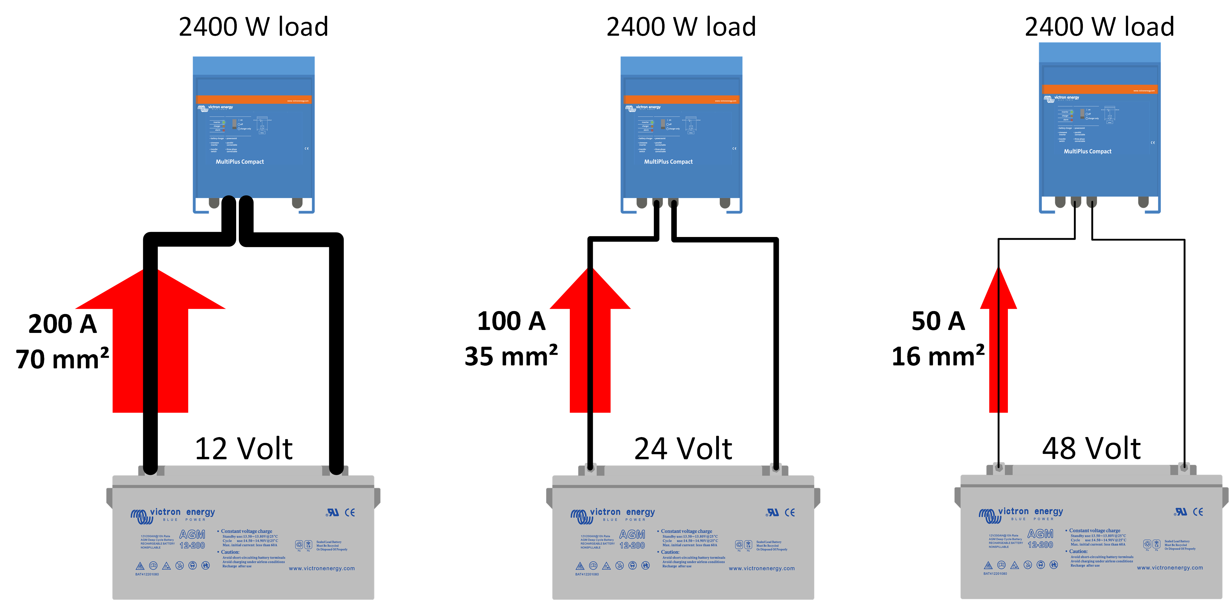
The preferred upper inverter power limits per system voltage are:
|
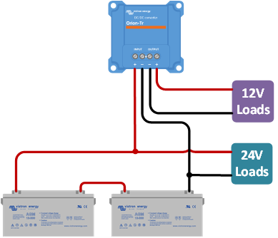
In order to avoid very thick cables, the first thing you should consider is to increase the system voltage. A system with a large inverter will cause large DC currents. If the DC system voltage is increased, the DC current will drop, and the cables can be thinner. If you want to increase the system voltage, but there are DC loads or DC charge sources that only can deal with 12V, you could consider using DC-DC converters rather than choosing a low voltage for the entire system. |
|
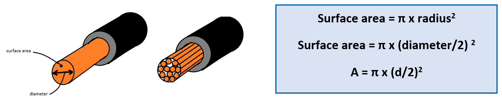
As explained already, it is very important to always use the right cable thickness. You can find the correct cable thickness in the product manual. Using a too-thin cable has a direct negative effect on system performance. Generally, cable core thickness is indicated in mm². This indicates the surface area of the cable core. But other annotations are used as well, like AWG (American Wire gauge). Please see the end of this chapter for a AWG to metric conversion chart. | ||
|  | |
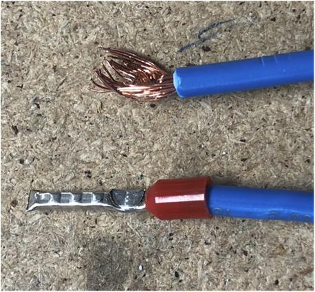
Be aware that some cables can have very thick insulation and they may appear thicker than they are. Find out the actual core diameter by looking at the cable marking or at its specifications, or alternatively do a physical check. Strip a bit of cable insulation away and look at the copper core of the cable and estimate the core diameter. In a solid cable, you can calculate the surface area if you measure the diameter of the cable core, but in a stranded cable this method is not that precise. (Please note that we do not recommend using solid core cables).
If you cannot find a thick enough cable, double up. Use two cables per connection, rather than one very thick one. But if you do, always make sure that the combined surface area of both cables is equal to the recommended surface area. For example, 2 x 35mm2 cables equal one 70mm2 cable. Larger Victron inverter/chargers are equipped with two positive and two negative battery connections, especially for this purpose. | ||
When selecting cables avoid these mistakes: ·
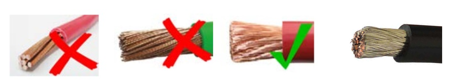 From left to right: non-flexible cable, cable with coarse strands, correct cable with fine strands, correct marine cable with tin coated strands. |
Calculating cable thickness can be difficult. There are ways to help you with selecting the correct cable thickness:
|
Product manuals: All our manuals recommend the DC battery cable size (and fuse size) that needs to be used for the product. |
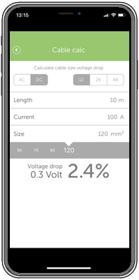
The Victron toolkit app: The Victron app helps you calculate cable size and voltage drop. The app is free of charge and can be downloaded here: https://www.victronenergy.com/support-and-downloads/software#victron-toolkit-app You can enter the following parameters:
Once the parameters have been entered, the app will calculate the voltage drop over both cables. You should aim for a voltage drop below 2.5%. |
|
Recommended battery cables table: The table below shows the maximum current for a number of standard cables where the voltage drop is 0.259 Volt. This table uses the total cable length, this is the length of the positive cable plus the length of the negative cable. Not that the losses over the contacts are not included.
|
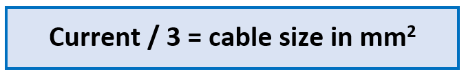
Rule of thumb: For a quick and general calculation for cables up to 5 meters use this formula:
For example: if the current is 200A, then the cable needs to be: 200/3 = 66mm2 |
AWG to Metric conversion chart This table shows the conversions and resistance for cables up to AWG 10. For the full table (up to AWG 40), see this link: https://www.victronenergy.com/upload/documents/AWG%20to%20Metric%20Conversion%20Chart.pdf
|
4.2. Busbars
Busbars are like cables, only they are rigid metal bars. They are made of copper or tinned copper. They are used in large systems where large currents flow. They provide a common positive and a common negative point between the batteries and multiple inverters. Busbars are also used in smaller systems, especially when there is a lot of DC equipment. A busbar in this case provides a nice location to connect all the various DC cables to. To calculate busbar thickness, simply use the recommended cable surface area and apply that to the busbar cross-section area. 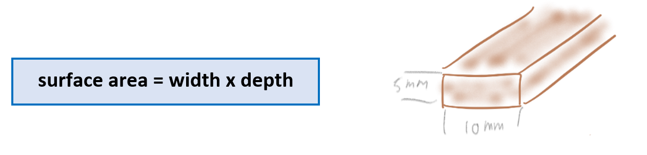 For example:
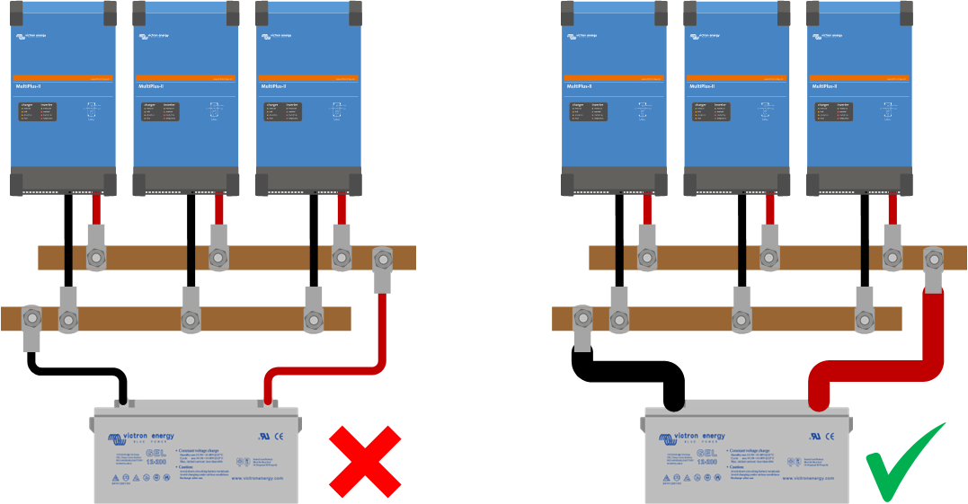
When wiring the system, please make sure that the cross-section of the connection between the batteries and the DC distribution point equals the sum of the required cross-sections of the connections between the distribution point and the DC equipment. See the below image for examples of this. | |
|
CautionCAUTION: Busbars are not insulated. To prevent short circuits or electric shock use insulated tools and do not wear metallic jewellery, | |
When using busbars, it is in most cases necessary to shield the busbar, especially if the busbar is out in the open. This is to prevent people from touching the busbar, or to prevent a short circuit if a metal object should accidentally fall across the positive and negative busbars and short circuit both busbars. An easy way to do this is to mount a Perspex sheet in front or over the busbar. See the image on the right. | 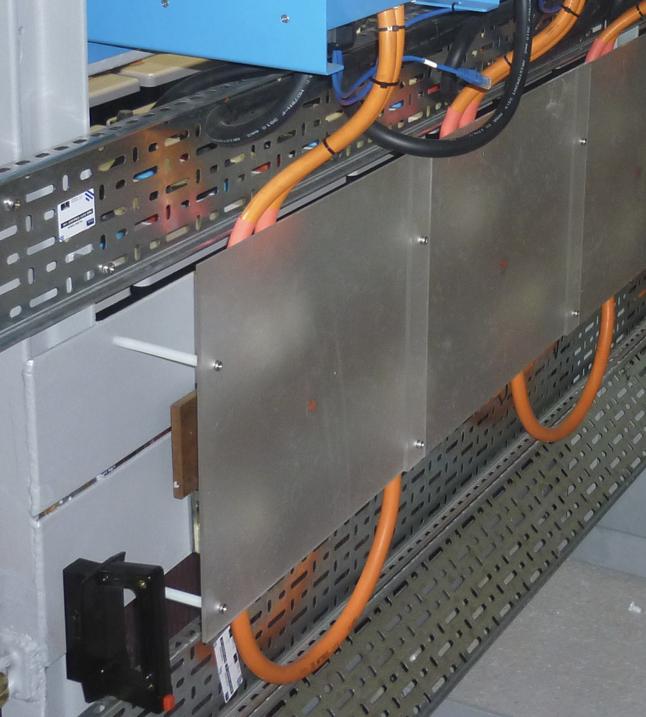 |
Busbars can be easily made by yourself, you simply need a copper or brass bar in which you drill holes so that electrical cables can be connected to the bar. For marine applications use tinned copper or brass. Busbars can be purchased from electrical wholesalers or metal suppliers. | 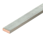 |
Victron has a number of products that contain busbars. These can also be found on our DC distribution systems and fuses product page. For the full product information follow this link: https://www.victronenergy.com/dc-distribution-systems. |
Victron busbar overview: | |||
Busbars that are rated at 150, 250 and 600A, with a variety of connection options and with and without covers (the 250A 6p model is pictured on the left). | 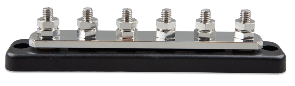 | ||
Fuse holder 6-way for MEGA fuses with a 250A busbar. | 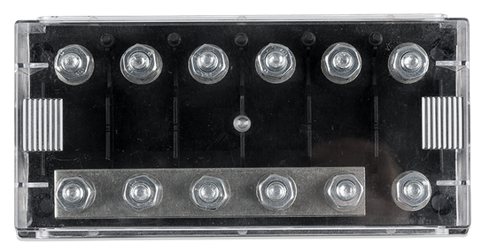 | ||
Modular MEGA fuse holders:
| 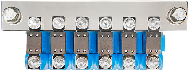 | ||
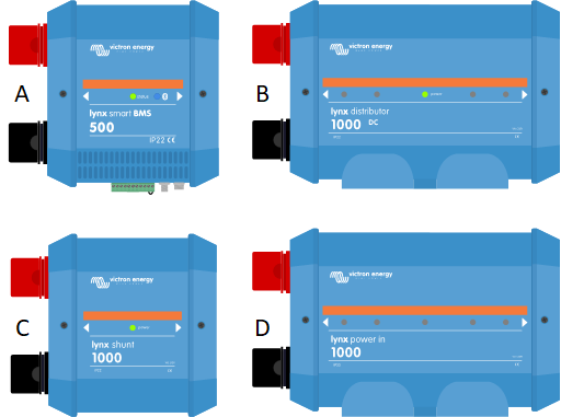
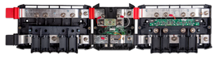
The Lynx distribution system consists of separate modules that can be connected to each other to form a continuous busbar for 12, 24 or 48V systems:
|
| ||
4.3. Cable connections
There are several ways to connect cables to batteries, Victron products, and other items in an electric system. |
Bolts, nuts, screws and eye lug terminals | ||
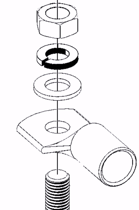
The common sizes for bolts of screws in Victron products are metric, like M5, M6, M8, and M10. Bolts for electrical applications are typically made of tinned brass. To prevent damage, always apply the manufacturer’s specified torque when tightening. Over-tightening can cause the bolt or nut to fail. Refer to the product documentation for precise torque. Cable eye lugs connect cables to bolts and must match the cable’s thickness. Use a special crimping tool to secure the lug to the cable. If the lug is uninsulated, ensure insulation is added afterwards. When connecting a cable eye to a bolt, arrange the components in this order: washer, spring ring, and then the nut. Ensure the lug is flush with the mounting surface. Avoid placing anything, such as washers or fuses, between the lug and the surface, as this can reduce the connection's current carrying capacity. | 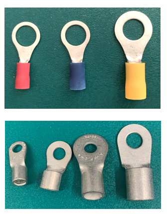 | |
Use insulated tools when tightening the nut. An accidental battery short circuit can be very dangerous, and the currents can melt your uninsulated spanner, or the spark can cause a battery explosion. 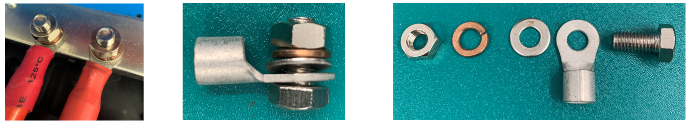 |
| |
Screw connectors | ||
Screw connector terminals come in a variety of types, shapes and sizes, suitable for thick or thin wires. For an indication of the minimum or maximum wire size that can be used in a screw connector, always refer to the product manual or manufacturer's documentation. 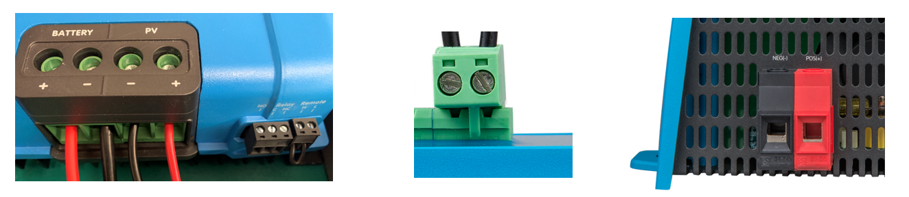 Some examples of screw terminals | ||
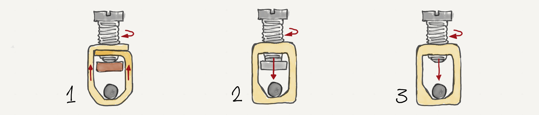
The basic screw connector terminal types:
| ||
From left to right: rising cage clamp terminal - pressure plate terminal - standard terminal | ||
Wire insertion Before inserting the cable, strip enough insulation to expose the bare wire. If required, use a ferrule to secure the wire strands. Ensure that no insulation enters the connector cavity, as this can increase resistance, leading to overheating and potentially melting the connector. Additionally, ensure no bare wire is visible outside the connector, as this poses a risk of electrocution or short circuits. | ||
| ||
The screws inside electrical connectors are typically made of tinned brass. When tightening, always apply the specified torque to avoid damaging the screw. Refer to the product manual or manufacturer's documentation for the correct torque values. | ||
Wire types and termination Generally speaking, do not use cables with a solid core, rigid or thick strands or where the strands are soldered together (unless the screw terminal is designed for this). This can result in poor electrical contact, leading to overheating or loosening of the connection. Ferrules are recommended to help align and secure the strands, ensuring optimal contact within the screw connector. For more details, refer to the following section. | ||
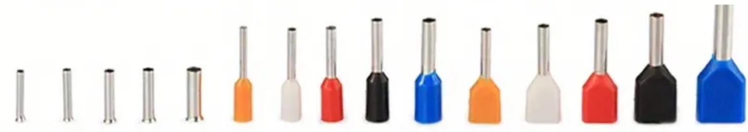
Ferrules | ||
Ferrules (also called wire-end ferrules or bootlace ferrules) are small sleeves that slide over stripped cable ends, holding the strands together for secure connections. | ||
Ferrule uses:
| ||
Ferrules come in various sizes and types to suit different cables and applications. They must be crimped onto the wire using a dedicated crimping tool. | ||
Ferrule types:
| ||
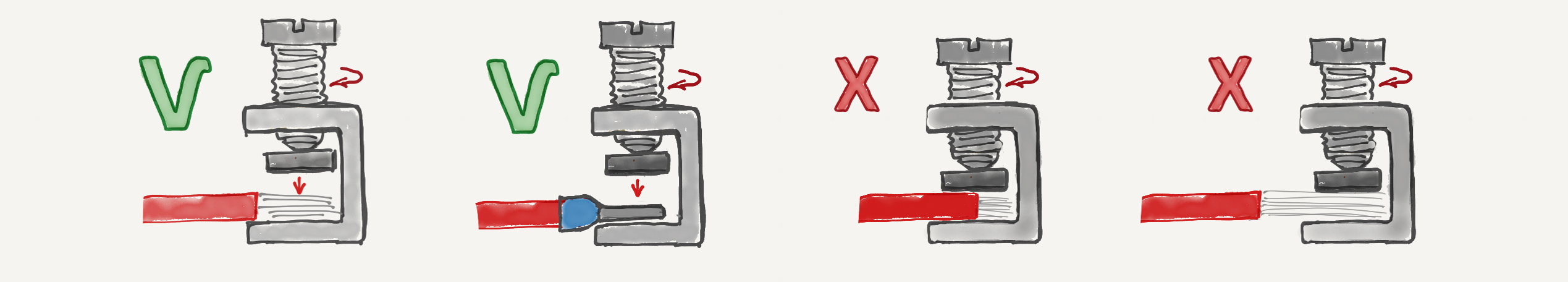
Ferrule usage with screw terminals Using ferrules is crucial when connecting wires to screw terminals, especially those without a wire cage or clamp. Here's when to use them:
| ||
Without ferrules, stranded cables may splay or get pinched by the screw, leading to incomplete contact or damage to the strands. The image on the right illustrates this: the top wire shows damaged strands with poor contact, while the bottom wire, protected by a ferrule, maintains full contact. |
| |
Ferrule crimping Always use a dedicated crimping tool to compress the ferrule securely around the wire strands, ensuring a durable, secure and gas-tight connection. Simply tightening a ferrule onto a wire without crimping leads to poor connections, as demonstrated in the image on the right: the top ferrule, which was not crimped, resulted in a weak connection, while the correctly crimped bottom ferrule provided a secure link. | 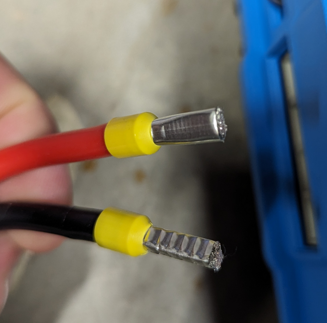 | |
Ferrule orientation Ensure the wire size and ferrule fit into the connector cage. The crimping shape should match the cage shape. When inserting the ferrule, align it correctly with the terminal cage orientation. | ||
Push connectors Push connectors are spring-loaded clamping connectors. Some are snap-in, and some are lever-operated and latch to prevent the wire from being pulled out again. | 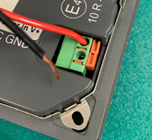 |
This is an example of how to use them:
| |
Spade terminals A spade crimp terminal must be crimped to the cable with a special crimping tool. These connectors include ones with and without insulation and some with special features, like piggyback connectors. | 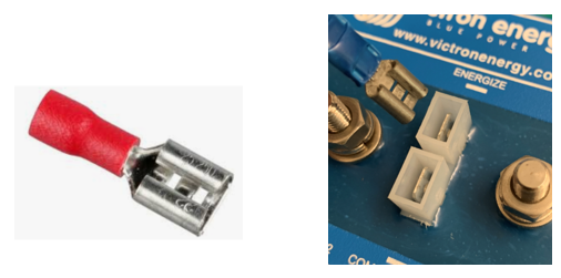 |
MC connectors These connectors are exclusively used to connect solar panels to other solar panels and/or to solar chargers. The most common is the MC4. Other types like MC1, MC2, and MC3 exist but are no longer used. The letters "MC" stand for MultiContact, which is the name of one of the original manufacturers that caught on. The digits 1 to 4 indicate the contact pin cross-section in mm2. | 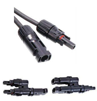 |
Some specifics:
For more information, see the Solar chapter. | |
RADLOKTM connectors Amphenol offers push-type DC connectors. These have a unique, positive locking mechanism that secures the connector in place and prevents accidental disconnection. The connector is designed to be highly reliable and highly resistant to environmental conditions such as vibration, temperature, humidity, and exposure to corrosive agents. Available in 70 - 400A models rated up to 1000V, these are often used with managed batteries. | 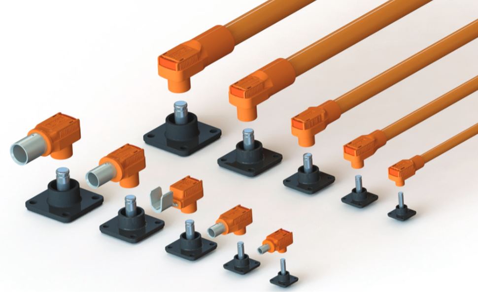 |
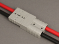
Anderson plugs Spring-loaded connectors made of tin- or nickel-plated copper to resist corrosion. They come in various sizes to accommodate different wire gauges and current requirements. They are often used in automotive or mobile applications where rapid connection and disconnections are common. Ensure the current rating matches the current when your system is under full load. They will add to the cable resistance if they are located between the battery and the inverter. In this case, limit or avoid their use. |
|
Car plugs These are generally used in low-end automotive applications. They are not capable of carrying currents beyond 10A, making them unsuitable for connecting an inverter. Also, consider that the car's circuit might only have an even lower fuse rating than 10A. When using these, take care to insert the plug correctly and deep enough. If not inserted correctly, the connector can heat up and melt. Limit or avoid their use. | 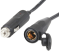 |
Battery clamps These are only meant for temporary connections. They often do not have a high enough current rating and should never be permanently used in an electrical system. Limit or avoid their use. |  |
4.4. Crimp terminals
Some special notes on insulated crimp terminals. These types of crimp terminals are readily available and are easy to use. They come in 3 colours, namely red, blue and yellow. These colours indicate the wire size that can be used with the crimp terminal:
The below table indicates the maximum current per crimp terminal colour when different cable lengths are used. 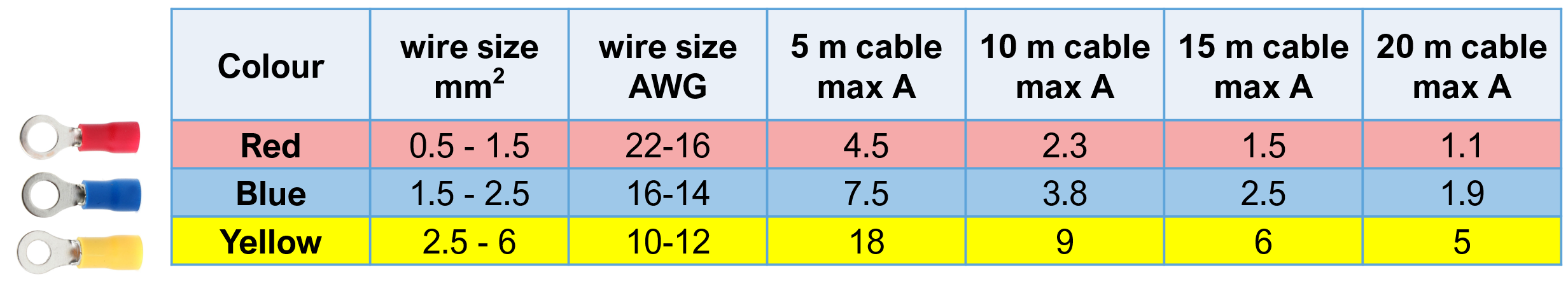 | |
The crimp terminals are available in a variety of different shapes as indicated in the below table. 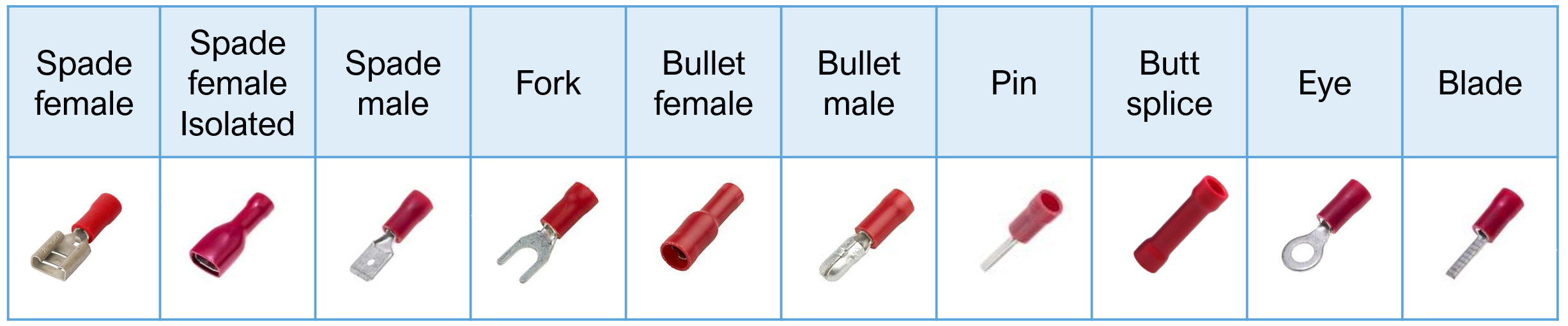 From left to right:
| |
Use a professional ratcheting crimping tool to properly crimp a terminal onto the cable. The ratcheting action ensures that the correct pressure is applied to the crimp. The tool has 3 crimping areas, which are indicated with red, blue and yellow dots. These dots correspond with the crimp terminal colour. See the below image for an example of a professional crimping tool. Also, before crimping, ensure the wire insulation is not pushed too deep into the crimp terminal. The crimp terminal has two different crimp sections, one for the wire core and one for the wire insulation. The professional crimping tool will crimp both sections at different pressure. After crimping, it is good practice to test the crimp by giving the wire a small tug, this is to ensure that the terminal is securely crimped.
|

4.5. Cable runs
When running and connecting cables between all the components in a system, there are a number of practical things to watch out for in regard to these cable runs. Although you would have followed the correct cable advice, there are still some cable-related factors at play that can cause a problem in a system. |
Use the correct cable thickness and if need be, double up: The Theory chapter of this book has explained why cables need to be a certain thickness and what are the negative effects if the cables are too thin. However, when wiring a system the required cable thickness might be not available or hard to obtain. Also, very thick cables are hard to manoeuvre or unable to make tight bends. In those cases, it is okay to use two cables instead of a single cable. A lot of inverters and inverter/chargers have double positive and double negative terminals for that exact purpose. When double cables are used it could be that each cable needs to be individually fused. The requirements can vary per country and per application, so please check your local regulations in regard to this. Then another local requirement can be that each individual conductor must be able to carry the full load, so in this case, doubling up cables is not possible, so please check the local regulations if this applies to you. |
Keep cables as short as possible: Try to keep the distance between high current cables, like battery and inverter or inverter/charger as close as possible. But do watch out, not to locate electronic equipment directly above lead acid batteries, even if the lead acid batteries are sealed. This is so you do not need to use very thick cables. The closer the batteries, the shorter the cable and the thinner the cable can be. |
Be aware that cables generate heat: Due to the cable resistance, the cables generate heat when current is passing through them. The higher the voltage drop over the cable, the more heat is generated. For example, if the voltage drop is 2.5%, this means that if 1000W of power travels through the cable, 2.5% of that power will be dissipated as heat. So for a 1000W load, this means 25W of heat. It is important that this generated heat can dissipate. If cables are enclosed, for example by cable conduit, the heat might not be able to dissipate and eventually the cables heat up too much. The only solution, in this case, is to increase the cable thickness and perhaps even double it. Use a cable conduit that is open at the top. Alternatively use thicker cables, so that the voltage drop is less and therefore less heat is generated. See the Current, cable resistance and voltage drop chapter and the The negative effects of cable voltage drop chapter for more information on this. A suggestion might be to run a system at full load and check the cables with a thermal camera. This is also a good way to detect loose cable connections or badly crimped terminals. |
Keep slack in the cables Tight cables together with vehicle vibration is not a good thing. The crimp terminals and battery poles are under too much stress and will come loose over time. A good example of this is the wiring between batteries to form a large battery bank. If the interconnecting wires do not have some slack and the batteries might not be totally immovable there will be too much strain on the battery terminals or the cable terminals and eventually, they will become loose or damaged. |
Use strain reliefs thick cables are heavy, do not let the full weight of a thick cable fully hang off an inverter, inverter/charger or battery connection. This is especially important if the installation is exposed to vibration. Strain reliefs or cable mounting brackets will take the weight of the cable. |
4.6. DC Fuses and circuit breakers
A fuse is an electrical safety device that protects wires in a circuit from excessively high currents, which can cause overheating or fire. The fuse is placed in the supply cable to an electrical device. As soon as current flows through the fuse that is higher than its current rating, for a certain amount of time, the fuse will blow. Once the fuse has blown, no more current will flow into the circuit. Higher-than-expected current situations could occur when an electrical device develops a fault or when there is a short circuit in the electrical circuit. The fuse protects wires and equipment against:
|  |
How does a fuse work? There are three types of fuse mechanisms, being:
|
The "one time only" fuse: Traditionally, a fuse contains a wire or a strip of metal that melts as soon as an unacceptable high current passes through the fuse. When the wire in the fuse has melted, the electrical circuit has been broken and no more current will flow in the circuit. Once the fuse has blown” it will need to be replaced by a new fuse to make the circuit operational again. These fuses are one-time use fuses. Once they have blown, they can’t be reset. They need to be replaced by a new one. | 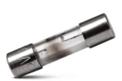 |
The re-settable (or automatic) fuse: Another type of fuse is the automatic fuse, often called circuit breaker or miniature circuit breaker (CB or MCB). These devices interrupt the current flow when high current is detected. Sometimes they will reconnect after the high current event has passed, or they need to be manually reset. They do not need to be replaced like the traditional fuses. | |
There are 2 ways how these fuses operate, either thermal or magnetic or a combination of these :
| 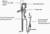 |
location of the DC fuses: Each consumer that connects to a battery needs to be fused. The fuse is placed in the positive cable. Each individual consumer needs to have an individual fuse. No matter how big or small the power rating of the equipment is. Batteries can potentially produce very high currents that can cause a fire. If the consumer develops a fault and internally short circuits, a very large current will flow, potentially causing a fire hazard. A DC circuit usually contains a main battery fuse, after which it branches off to the individual consumers. Each consumer has an individual fuse. | 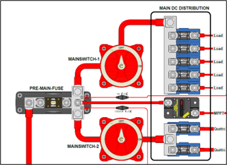 |
Location of the AC circuit breakers: The circuit breakers are located near the entry point of the public grid and/or the generator into the switchboard. The AC breaker is placed in the live conductor or in both the live and the neutral conductor. Single or double pole circuit breakers are used. There usually is one main circuit breaker per AC supply, after which the supply branches off into a variety of groups. Each group contains a circuit breaker, protecting a group of AC consumers. | 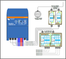 |
Location of the PV array circuit breakers: A fuse needs to be located between a PV array and the solar charger. Please check with the local authorities, regulations per application and country will vary. | 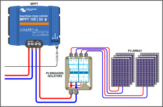 |
Fuse holders Fuses need to be placed in fuse holders. The fuse holder securely holds the fuse in place. And in some cases, they also provide electric insulation. Circuit breakers are usually mounted on DIN rail. Fuses and circuit breakers are usually located in a switch board, preferably inside an enclosure. |
Fuse ratings and how to select the correct fuse: When selecting a fuse there are 4 selection criteria: ·
It is important to choose the correct fuse that will match the circuit and match the power consumption of the equipment in that circuit. The rating of the fuse is displayed on the fuse or can be found in the fuse’s datasheet or its specifications. |
Current rating If there is only one consumer in a circuit, the fuse will need to match the current rating of that consumer or the current rating of the cable, whichever is the lowest of the two. If there are multiple consumers in a circuit, then the fuse will need to match the current rating of the cabling in the circuit. |
Voltage rating The fuse voltage rating needs to be equal to or bigger than the expected maximum voltage in the system. The fuse needs to be specifically rated for the required type, DC and/or AC. Most DC fuses are suitable for 12 and 24 V, but they are not necessarily suitable for 48 V and higher. Please note that not all fuses or circuit breakers can be used in both AC and DC circuits. If the fuse is able to be used for both AC and DC, the voltage for AC is often rated higher than the DC voltage rating. Also, take care that circuit breakers might not be unidirectional, so for DC, it matters which way they are wired into the circuit. |
Speed The speed of a fuse is the time it takes for the fuse to open when a fault current occurs. This is dictated by the fuse material, its mechanism, the current and the temperature. There are slow and fast blow fuses:
Fuse element speed range:
|
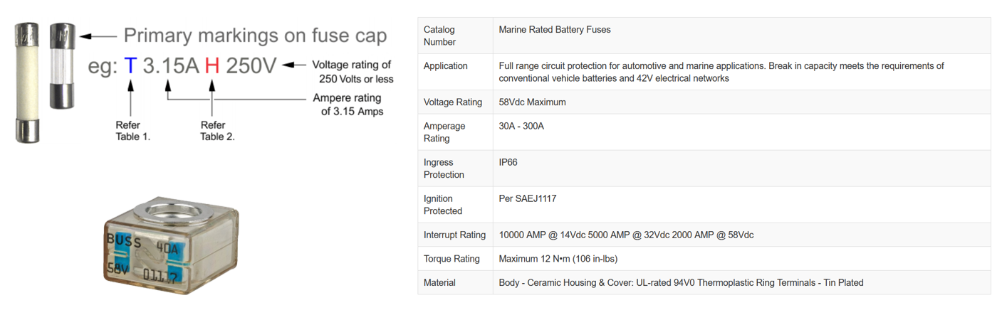
Fuse markings The fuse contains marking as to what its ratings are. But information might be missing. Then a good source to find out more are the fuse specifications. These can be easily found online or from your fuse supplier.
|
Overview of fuse types: |
Fuse type | Fuse | Fuse holder |
|---|---|---|
Glass or ceramic fuses
| 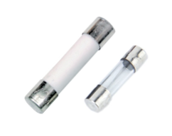 | 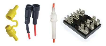 |
Blade fuses (automotive)
| 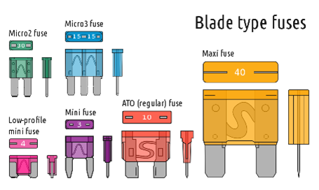 | 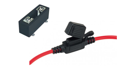 |
Midi Fuses
| 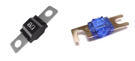 | 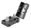 |
Cooper Bussmann MRBF fuses
|  |  |
CNN fuses
| 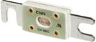 |  |
Mega fuses
|  | 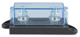 |
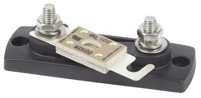
ANL fuses
|  | 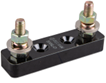 |
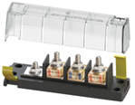
NH fuses
| 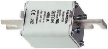 |  |
Circuit breakers (CB or MCB)
|  |  |
4.6.1. Interrupt rating and fuse selection for lithium systems
Lithium batteries can deliver very high short-circuit currents. In the event of a fault, the prospective fault current can be far higher than in comparable lead-acid systems. For this reason, when selecting the fuse, not only the continuous current rating but also the interrupt rating needs to be considered.
The interrupt rating, sometimes referred to as breaking capacity, is the maximum fault current a fuse can safely interrupt without fusing, rupturing, or exploding. If the interrupt rating is lower than the available short circuit current, the fuse may fail catastrophically.
In every lithium battery installation, at least one fuse in the DC line must have an interrupt rating equal to or greater than the maximum prospective short circuit current of the battery bank. This is a mandatory safety requirement.
T fuses
The T fuse is a high-performance solution with a very high interrupt rating and fast response. It is well-suited for lithium battery systems and integrates neatly into the Lynx system. However, it is not always readily available in all markets.
Alternative fuses
Suitable alternative fuse types with adequate interrupt rating may be used, provided the continuous current rating, DC voltage rating, and interrupt rating match the system parameters.
Fuse overview
Fuse | Max DC voltage | Interrupt current rating |
|---|---|---|
Class T fuse (Eaton Bussmann) | 160 V | 200 kA |
Class T fuses (various manufacturers) | 125 to 300 V | 20 kA |
NH blade fuses (various manufacturers) | 250 V | 25 kA |
Blue Sea ANL fuse (Blue Sea) | 80 V | 6000 A |
AMX(L) fuses (Eaton Bussmann) | 125 V | 3000 A |
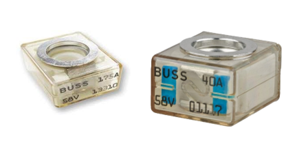
Littlefuse MEGA fuse (Littlefuse) | 70 V | 2500 A |
MRBF Terminal fuse58V (Blue Sea) | 58 V | 2000 A |
Littelfuse MEGA fuse (Littelfuse) | 58V | 1000 A |
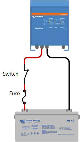
4.7. DC isolation switches
A battery isolation switch can be used to isolate the battery (or battery bank) from the rest of the electrical circuit. Or it can be used to isolate a DC source or DC consumer from an electrical circuit. Being able to isolate a battery or DC consumer from the electric circuit is useful in case the system is not going to be used for a certain amount of time or for system maintenance. When selecting an isolator switch always make sure that the isolator switch is rated to the currents that can be expected in the system under full load. The rules and guidelines for battery isolation vary in different countries, but it is recommended that if battery isolation is needed, to only isolate the positive battery cable. It might not even be necessary to add an isolator switch. A DC system should always contain a main fuse. Removing the fuse will also break the circuit. So, when the system needs to be maintained or if the battery needs to be replaced, removing the main fuse will be sufficient to isolate the battery from the rest of the system. |
| |
Always use quality isolator switches. The isolator switch will add to the circuit resistance. A low-quality switch will have more resistance, this can potentially increase the voltage drop and will cause system issues. Isolator switches are rated for a certain voltage and a continuous current (make sure it is DC current) and are often also rated for a 5-minute current and a few seconds peak current. Some isolator switches are not designed to break current (especially DC current) and some battery switches cannot switch under load. Please refer to the isolator switch technical specifications. Types of isolator switches:
| ||
|
|
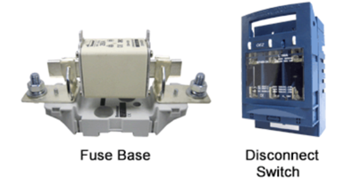
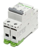
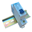
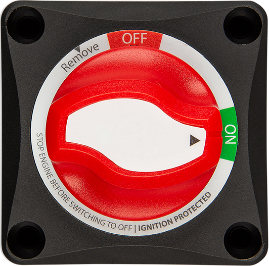
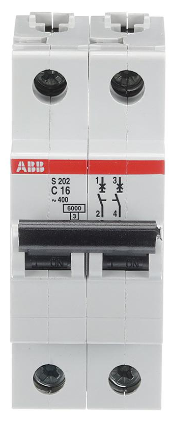
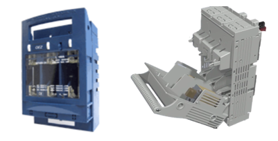
| |||
Victron Energy Battery Switch ON/OFF 275A. | High current DC MCB. | NH fuse holders can be used as a circuit breaker. |
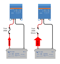
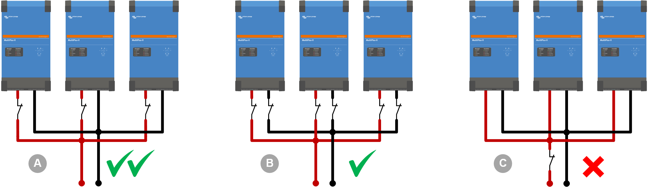
Systems with multiple inverters or inverter/chargers Each unit must be fused individually, using the same type of fuse for each unit. This ensures that each DC path has the same resistance. Avoid using a single large circuit breaker or fuse for the entire system. A short circuit or other failure in an individual inverter/charger will rarely have a low enough resistance to trip the large fuse. If the fuse does not trip, the current will continue to flow at a dangerously high level, potentially damaging the inverter/charger's internal or external wiring. It is preferred, though not mandatory, to maintain a continuous negative DC connection in the system and only switch, protect, or fuse the positive DC connection of each inverter/charger. This preference is due to the difficulty in troubleshooting a loose connection in the DC negative path, particularly in systems with multiple units (parallel, split, or three-phase). However, a continuous negative connection is not required, as some installations necessitate that the DC negative be protected by a fuse or circuit breaker. | ||
|
| |
4.8. Shunt
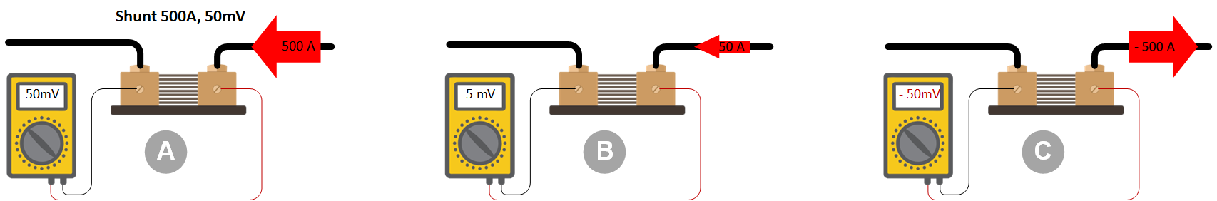
A shunt is added to a system to measure current flow and is used for system monitoring and battery state-of-charge calculations. A shunt is a resistive element used to measure current. When current flows through the shunt, a small voltage drop proportional to the current is created. This voltage drop increases with larger currents and decreases with smaller currents. If the current flow reverses, the voltage drop will reverse polarity. By measuring the voltage drop across the shunt, the amount and direction of the current can be determined. This information can be used to determine how much current enters or leaves a battery to calculate the battery's state of charge. A shunt has a current and a voltage rating, for example, 500A, 50mV. This indicates that a 500A current passing through the shunt will cause a 50mV (0.05V) voltage drop across it. | ||
|
| |
The shunt must be rated for the maximum DC current that will flow into the system's combined consumers. Example: An inverter connected to a battery will have a maximum current equal to its peak rating. A 3000VA inverter with a peak power of 6000W at 12V will draw a 500A current. | ||
|
| |
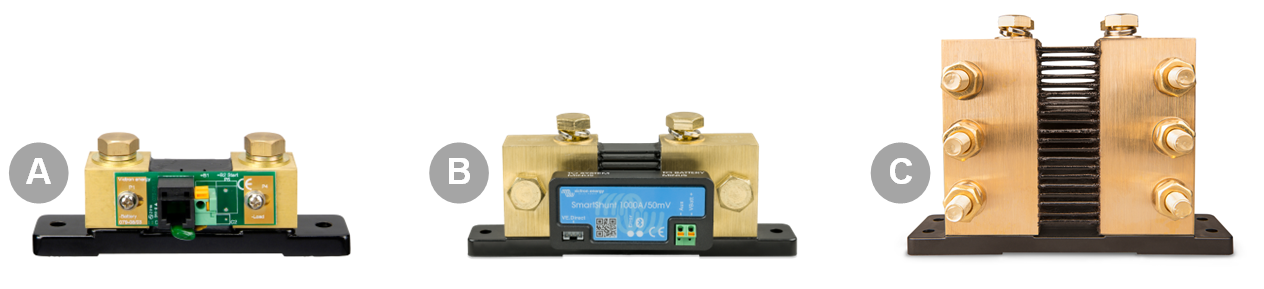
The Victron SmartShunt is available in 500A, 1000A, and 2000A 50mV versions. The Victron BMV battery monitor comes with a 500A, 50mV shunt. If this shunt is insufficient, you will need to upgrade to a larger one. Victron offers 50mV shunts in 500A, 1000A, 2000A, and 6000A options. When using a shunt with different voltage or current ratings, ensure you adjust the shunt parameters in the BMV battery monitor settings. | ||
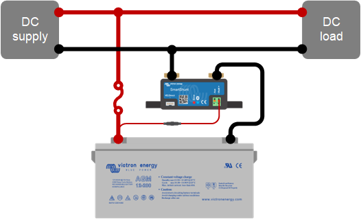
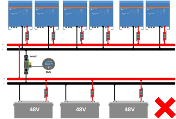
For safety reasons, the shunt is typically placed in the negative cable. It should be the last component before the battery bank or battery bank busbar. All DC consumers and supplies must be connected after the shunt. Refer to the diagram on the right for proper wiring of the shunt into a system. Shunts can also be located elsewhere in a system, such as measuring a specific DC consumer or supply. These shunts are usually connected to a current meter. |
| |
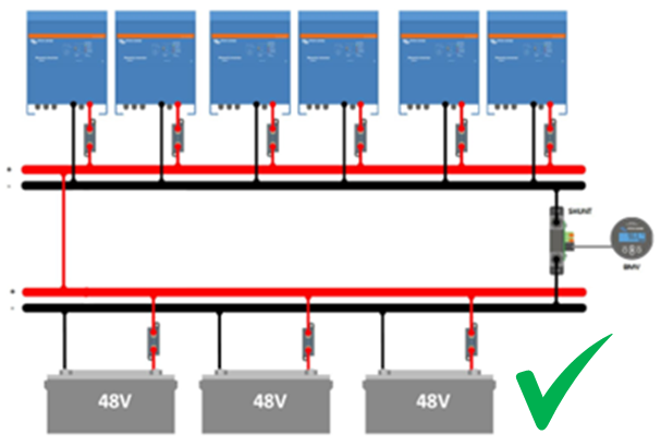
Misplacing the shunt can cause issues, especially in large systems where there is a long path between the battery and inverter/chargers. When inverting, the inverter/charger near the shunt will "see" a lower DC input voltage than those further away. Conversely, when charging, the batteries near the shunt will "see" a lower DC input voltage than those further away. See the images below. To resolve this, either move the shunt away from the positive cable (though this is not ideal) or consider using smart batteries that generate their own state of charge, eliminating the need for a shunt. | ||
|
|
| |||
The shunt is incorrectly placed. | The shunt is correctly placed. | Smart batteries are used, and no shunt is needed. |
4.9. Parallel and/or 3-phase system DC wiring
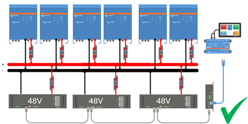
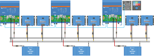
A large inverter/charger or a 3-phase inverter/charger can be created by connecting multiple inverter/chargers together. These units communicate with each other and, together, they become one large inverter/charger. They all need to be connected to the same battery bank. When wiring an installation like this, there are some important considerations regarding the battery cables. For correct operation, it is essential that each unit receives exactly the same voltages. To ensure this, the DC path from the battery bank to each individual unit, or from the busbar to each individual unit needs to be exactly the same. If there is a difference between the cable thickness or the cable length between the individual units, there will be a difference between the voltages of these units. | ||
Different voltages mean different currents. The unit with a lower voltage will have a higher current running through its power electronics. Inverter/charger overload is triggered by the amount of this current. So, although the power that each inverter delivers will be the same, the unit with the lower voltage will have a larger current running through it and will go into overload before the other units do. The total inverter power of the system will now be less because when one unit goes into overload, the whole system will stop working. The unit with bad wiring will determine the performance of the whole system. |
| |
To achieve a balanced system, you will need to use the same cable type, cross-section and cable length for each unit from the battery bank or from the busbars. Also, ensure that all cable lugs are identical, and all connections are tightened with the same torque values. Consider using busbar power posts between the battery bank and the inverter/chargers. When placing fuses into the installation consider using only one DC fuse per phase. If a big single fuse is not available, then use one fuse per unit, but make sure that all these fuses are exactly the same. | ||
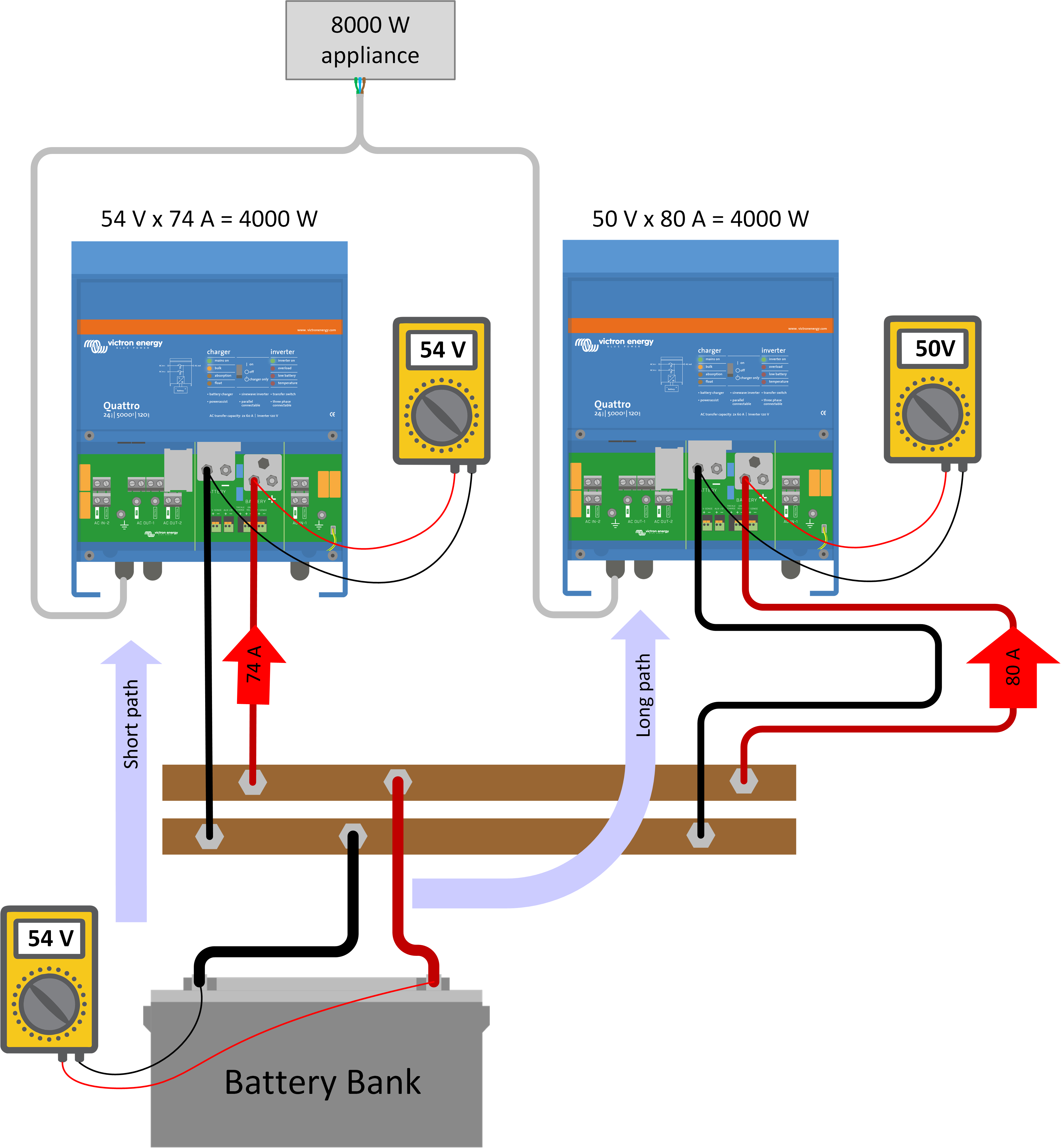
To check if a system is correctly wired or to troubleshoot wiring follow these steps:
| 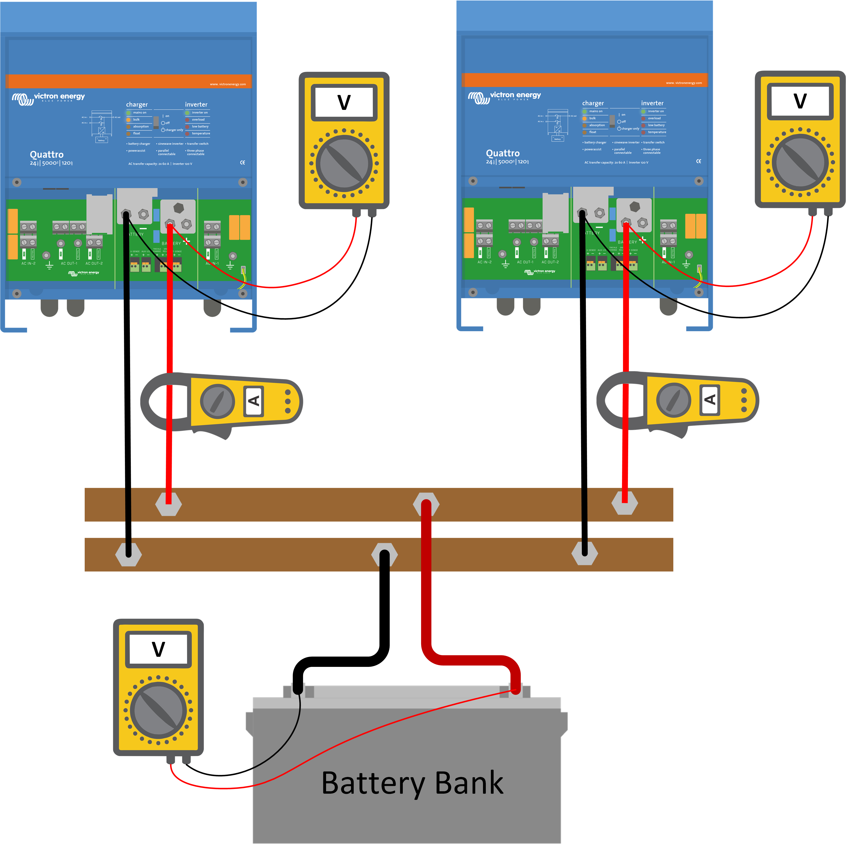 |
Alternatively, you can measure the voltage on the busbar or battery bank and compare this with the voltages you measure at each unit’s battery terminals. All these voltage readings should be identical. For more info on parallel and 3 phase systems see this link: https://www.victronenergy.com/live/ve.bus:manual_parallel_and_three_phase_systems. | |
4.10. Large system busbars
Large installations typically consist of multiple DC consumers and DC sources. Like multiple batteries, multiple inverter/chargers and multiple solar chargers. They all connect to a central busbar. When wiring these installations, special considerations need to be made. | |
In these systems, you will need to use busbars, but even still, it matters how all equipment is connected to the busbar and in what order. It is important to alternately connect the inverter/chargers and the solar chargers to the busbars. The reason is that this will reduce the current flowing through the busbars. To simply put it, the current entering the busbar from a solar charger can travel via a short path straight into the inverter or into a battery. This current does not need to travel through the entire busbar. It keeps the local “traffic” low. | 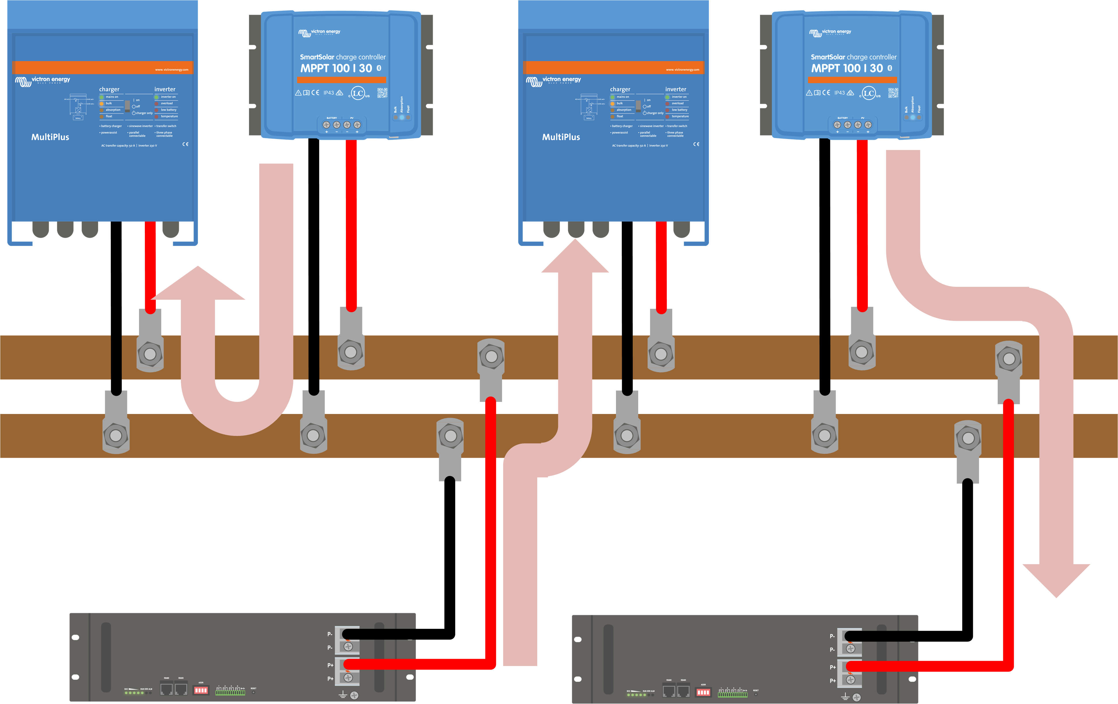 Current flow via the busbar. |
When wiring, make sure all inverter/chargers have the same cable length. Also, the solar chargers need to have approximately the same cable length. And the same for the batteries. | |
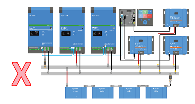 Do not have all inverter/chargers on one side and the solar chargers on the other side. | 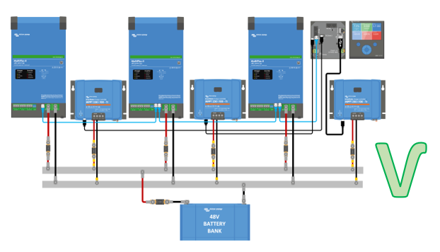 Intermix the inverter/chargers and the solar chargers. |
If the system has only one battery bank you should connect the battery bank in the middle of the busbars. But in the case of several parallel battery banks or smart batteries, they should also be distributed evenly along the busbars. | |
 If the system has individual batteries, also intermix these with the inverter/chargers and the solar chargers. | |
4.11. Voltage sensing and compensation
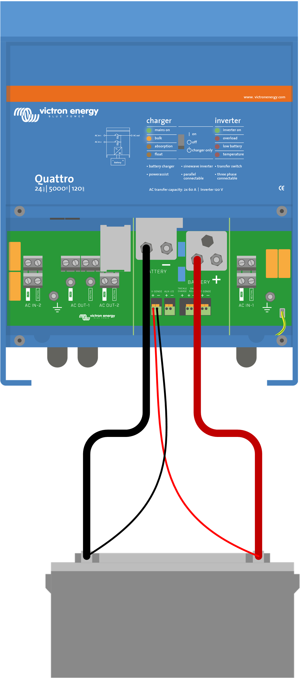
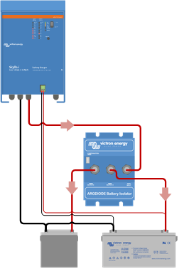
Voltage sensing is a battery charger feature. It works by measuring the difference between the voltage in the unit and the voltage at the battery terminals. As soon as a difference is detected, the charge voltage will be increased to compensate for cable losses during charging. This will ensure that the batteries are always charged with the correct voltage. This feature generally will only compensate for voltage losses up to 1V. If the losses in the system are bigger than 1V (i.e. 1V over the positive connection and 1V over the negative connection), the battery charger, solar charger or inverter/charger will reduce its charge voltage in such a way that the voltage drop remains limited to 1V. The reason behind this is, that if the losses are bigger than 1V, the battery cables are too thin and are unable to carry a large current and therefore the charge current needs to be reduced. Voltage sense can also be used to compensate for voltage losses when diode splitters are used. A diode splitter has a 0.3V voltage drop over the diode. Some Victron products, like an inverter/charger or large chargers, have voltage sense built in. For other products, such as solar chargers and Smart battery chargers you will need to add a Smart Battery Sense. If the product has a voltage sense (V-sense) terminal, two wires can be connected from the V-sense terminal directly to the battery's positive and negative terminals. Use a cable with a cross-section of 0.75mm². |
Voltage sensing inverter/charger |
Large charger with voltage sensing and diode splitter |
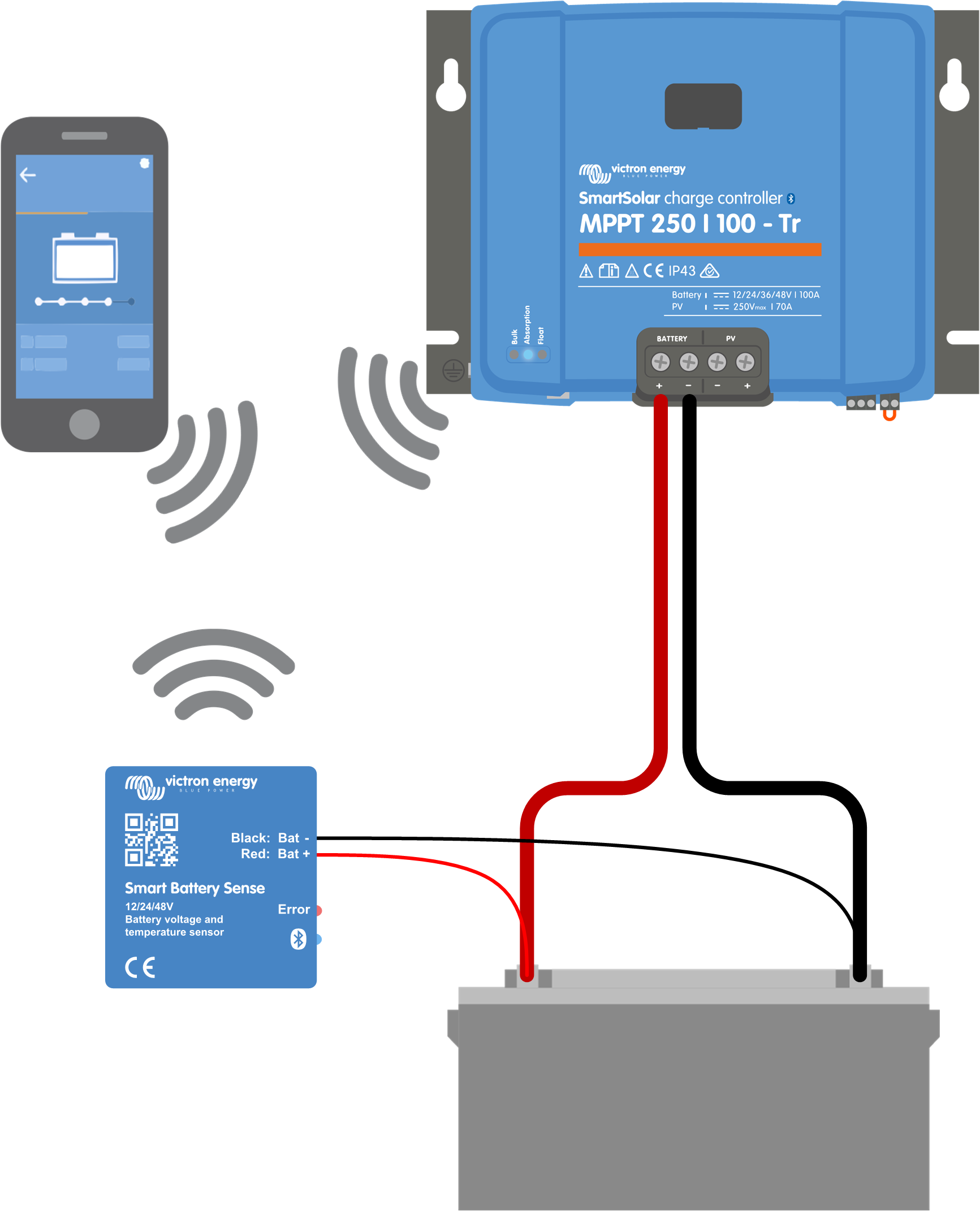
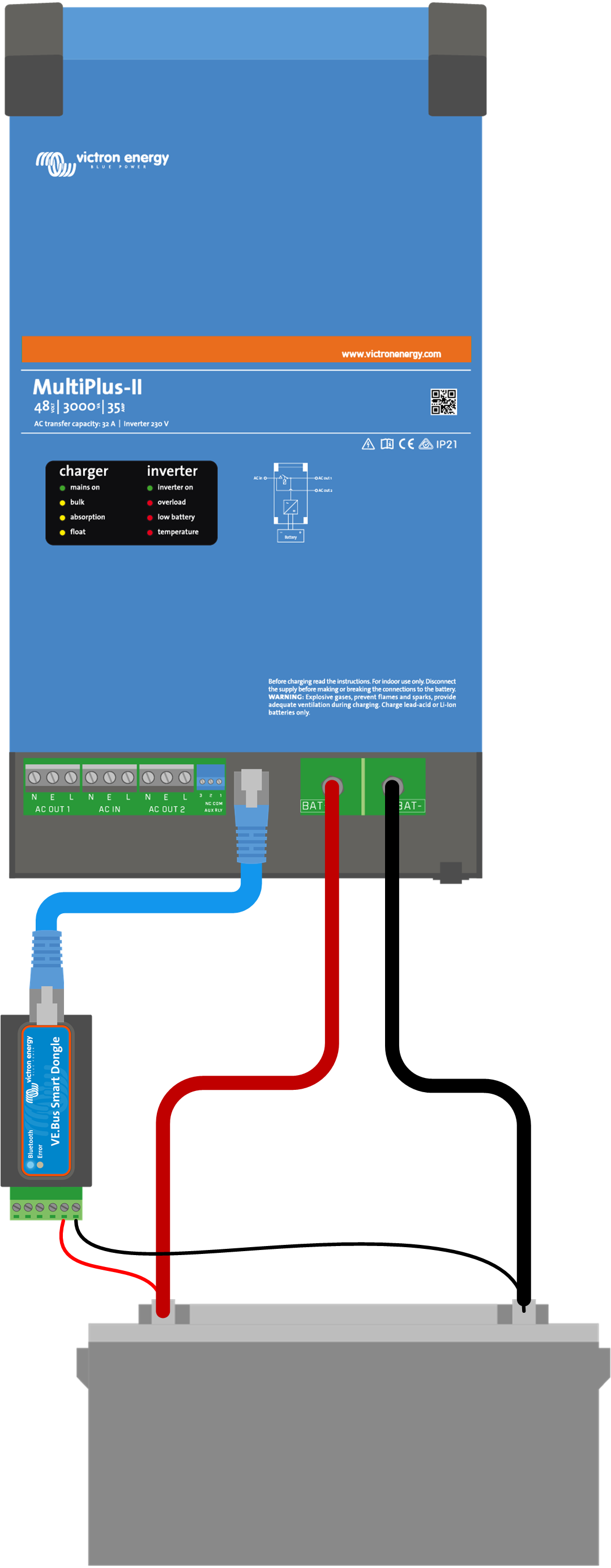
If an inverter/charger is equipped with a VE.Bus Smart dongle, there is no need for voltage sense wires because the dongle takes care of voltage sensing. For more information on the VE.Bus Smart dongle see this link: https://www.victronenergy.com/accessories/ve-bus-smart-dongle. In the case of a solar charger or a Smart charger, connect a Smart Battery Sense to the battery and set up Smart Networking using the VictronConnect app. For more information on the Smart Battery sense see this link: https://www.victronenergy.com/accessories/smart-battery-sense. |
Smart Battery Sense |
VE.Bus Smart dongle |
Voltage sensing in an Energy Storage System (ESS) with a DC solar charger In an ESS system (Energy Storage System) that only contains DC solar chargers (without grid-feed inverters), the charger of the inverter/charger is disabled. This is because the solar charger charges the battery and excess solar power is fed back into the grid. This process is controlled by the GX device. To make this work, the GX device will set the solar charger at a higher DC voltage than the inverter/charger’s DC voltage. When the battery is almost full, the battery voltage will be slightly higher than the inverter/charger’s DC voltage. This is the “cue” for the inverter/charger to reduce this “overvoltage”. It does this by feeding power into the grid. In a 48V system, this overvoltage is set at 0.4V, and in a 24V system, this is 0.2V. For this process to work properly, it is essential that the battery receives the correct voltage from the solar charger. Special care is needed as to the design and placement of the DC cabling, fuses and connections, as they can potentially cause a voltage drop in the system. A voltage drop can reduce the “overvoltage” the inverter/charger needs before it can feed power into the grid. Example of an ESS system with a 100A solar charger, two 1-meter 35mm² cables and a 150A fuse:
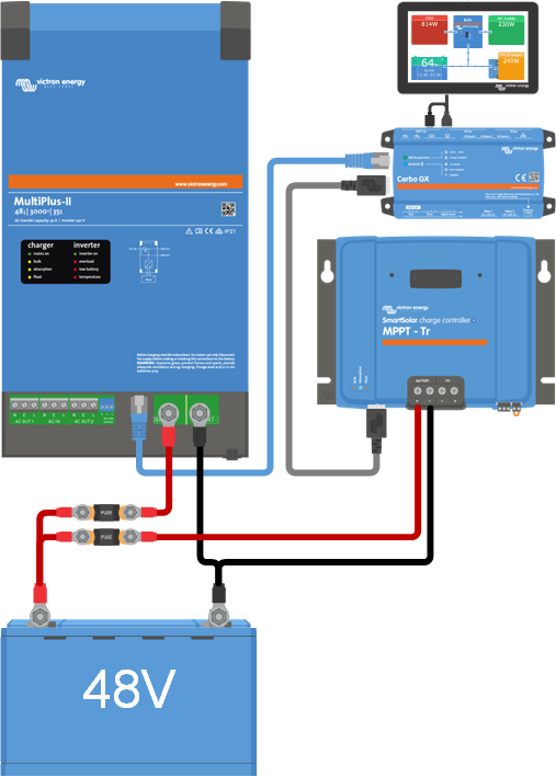
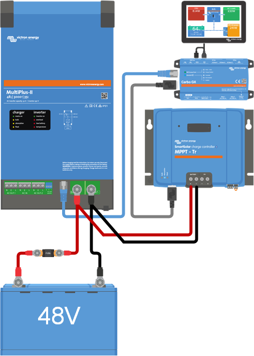
The solution is to use a solar charger with automatic voltage drop compensation (voltage sensing). The result will be that the output voltage of the solar charger will slightly increase with increasing current. But if the solar charger does not have voltage sensing, then it is best to connect the solar charger directly to the inverter/charger. |
ESS system with a solar charger connected to the battery. |
ESS system with a solar charger connected to the battery. |
4.12. Solar
Solar panels are not allowed to be directly connected to a battery. A solar charger needs to be placed between the solar panels and the batteries. The solar charger converts the higher solar panel voltage into a voltage suitable for battery charging. If a solar panel is connected directly to a battery, the battery will get damaged. |
Safety: Depending on local regulations, a fuse, circuit breaker, RCD or GFCI might need to be installed between the PV array and the solar charger. |
MC4 connectors: To connect solar panels to a solar charger the solar panel is in most cases fitted out with special waterproof connectors, commonly these are MC4 connectors. These connectors come in 2 varieties, a male connector and a female connector. The male connector connects to the positive cable coming from the solar panel and the female connector connects to the negative cable. In case the solar cables are not long enough, an extension cable will need to be used. The extension cable is often pre-assembled with MC4 connectors. A solar cable is fitted out with a male connector on one end and a female connector on the other end. Like this: MC4 connectors can be connected to 4mm2 or 6mm2 solar cables.
Solar cable. On the left is the male MC4 connector and on the right is the female MC4 connector. |

Solar cable types: | ||
A solar cable is a special cable. It is a very tough cable and has been designed for outdoor use in solar panel installations. It is dust, age and UV resistant and has tinned copper wire strands. | ||
A solar cable for small PV arrays, like for Automotive or marine applications is often a dual-core cable. Again, the same applies to these installations, the cable must be UV rated and will need to have tinned copper wire strands. |
| |
A solar cable for small PV arrays, like for Automotive or marine applications is often a dual-core cable. Again, the same applies to these installations, the cable must be UV rated and will need to have tinned copper wire strands. | 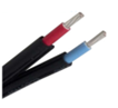 | |
Cable thickness: The cable thickness of the solar cable depends on the size of the solar array and what voltage it has. This will determine the current and this will determine cable thickness. Please see chapter Cable selection for more information on this. |
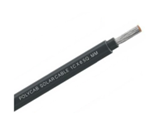
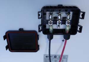
Connecting to a solar panel: Solar chargers are sold in two models, with either MC4 connectors or with screw connectors on the PV side. This is how to connect them to a solar panel as seen from the rear of the solar panel: | ||
|  | |
Solar charger with MC4 connectors. | Solar charger with screw connectors. | |
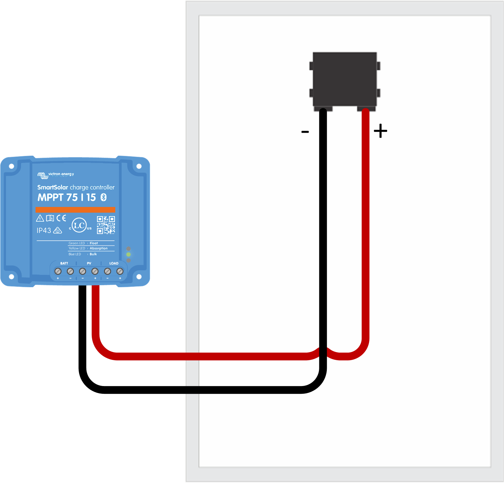
In some occasions, the solar panel does not have cables attached. You will then need to attach these yourself. To do this, open the junction box at the rear of the panel and connect the cables there. You can either use solar cables with or without MC 4 connectors. If you are wiring the solar panel directly to the solar charger, then this is what the installation will look like: | ||
|  | |
Connecting a solar charger to a solar panel without using MC4 connectors. | Solar panel junction box. | |
Solar arrays: In many solar installations, one solar panel is not enough. If this is the case, a solar array or photovoltaic (PV) array needs to be created. A Solar array consists of multiple solar panels that are connected together. If you connect solar panels in series the voltage increases and when you connect them in parallel the current increases. The same is the case when constructing a battery bank with individual batteries. |
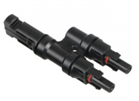
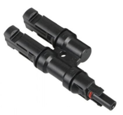
MC4 splitters: To make parallel connections easy, use MC4 solar splitters. There are two types: | |||
|
| ||
MC4-Y - 1 male and two female. | MC4-Y - 1 female and 2 male. | ||
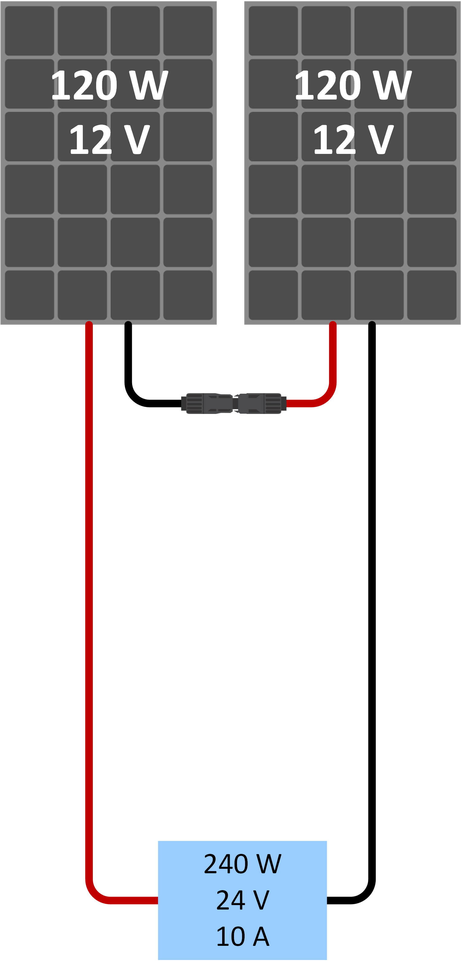
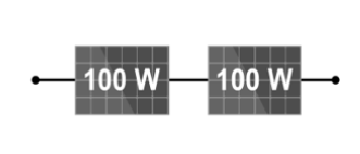
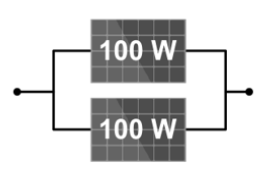
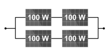
Solar array wiring examples Some solar array wiring examples that show pales wired in series, paralell and series/parallel using MC4 splitters. | ||||
|
| 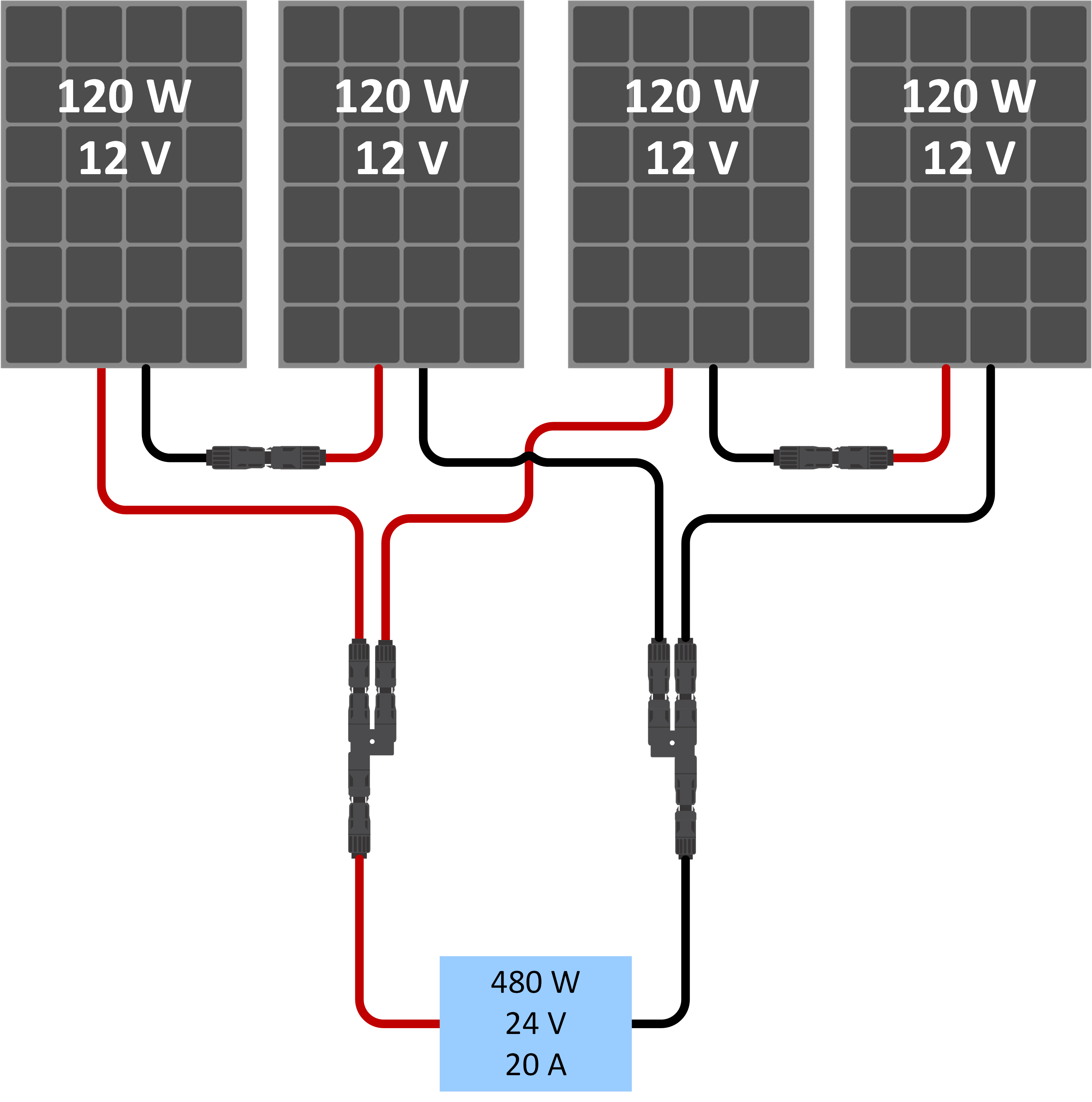 | ||
Series solar array. | Parallel solar array. | Series/parallel solar array. | ||
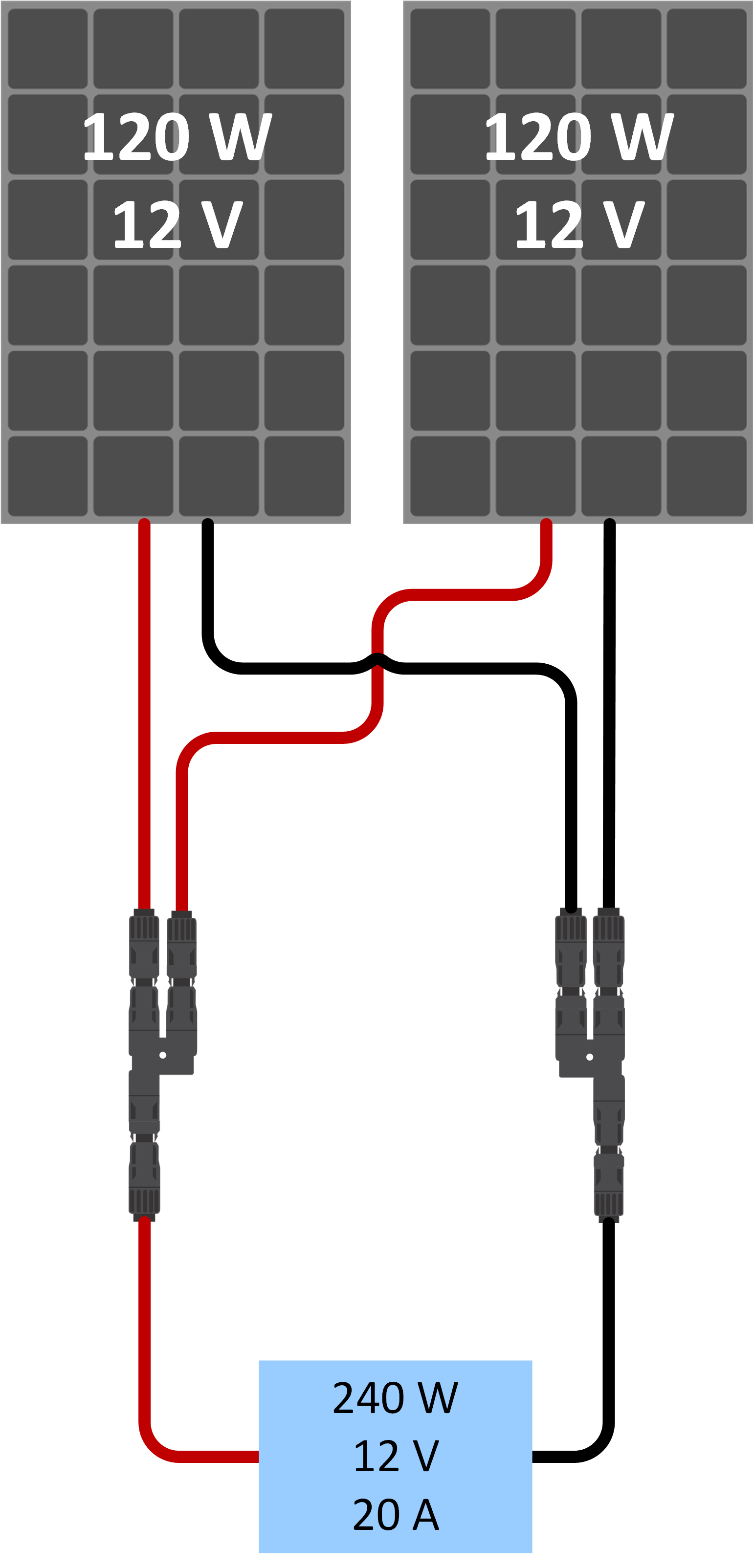
Solar array total power To determine the total power of a solar array, you will simply have to add the power of each module no matter if they are connected in parallel or in series: | ||
 |  |  |
200W solar array. | 200W solar array. | 400W solar array. |
Solar array total voltage: When designing a solar array, you will need to make sure that the array's open circuit voltage (Voc) does not exceed the voltage rating of the MPPT. For some extra information on designing a solar array: | |
An example of array voltage when panels are connected in series: If you look at the specs of a 12V solar panel, you will find that the Voc is around 22V. For a 75/15 MPPT solar charger, the solar voltage can be as high as 75V. This will allow you to connect up to 3 x 12V panels in series. | 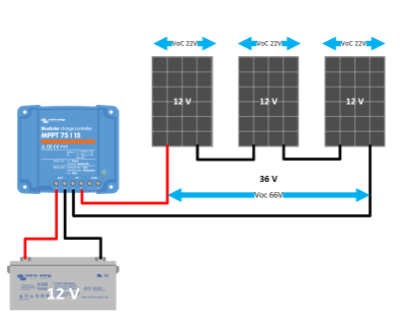 |
Note on MPPT charge current at different battery voltages: Example: For a 75/15 MPPT solar charger, the current rating is 15A. This is the current going into the battery. This means that with a 12V battery you will get less power into the battery than with a 24V battery. | 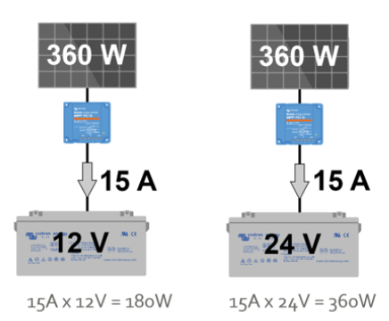 |
To help you design a solar array and to match it to the correct solar charger: Use the Victron MPPT sizing calculator, see here: https://www.victronenergy.com/solar-charge-controllers. |  |