4. VictronConnect setup, configuration and operation
4.1. Setup
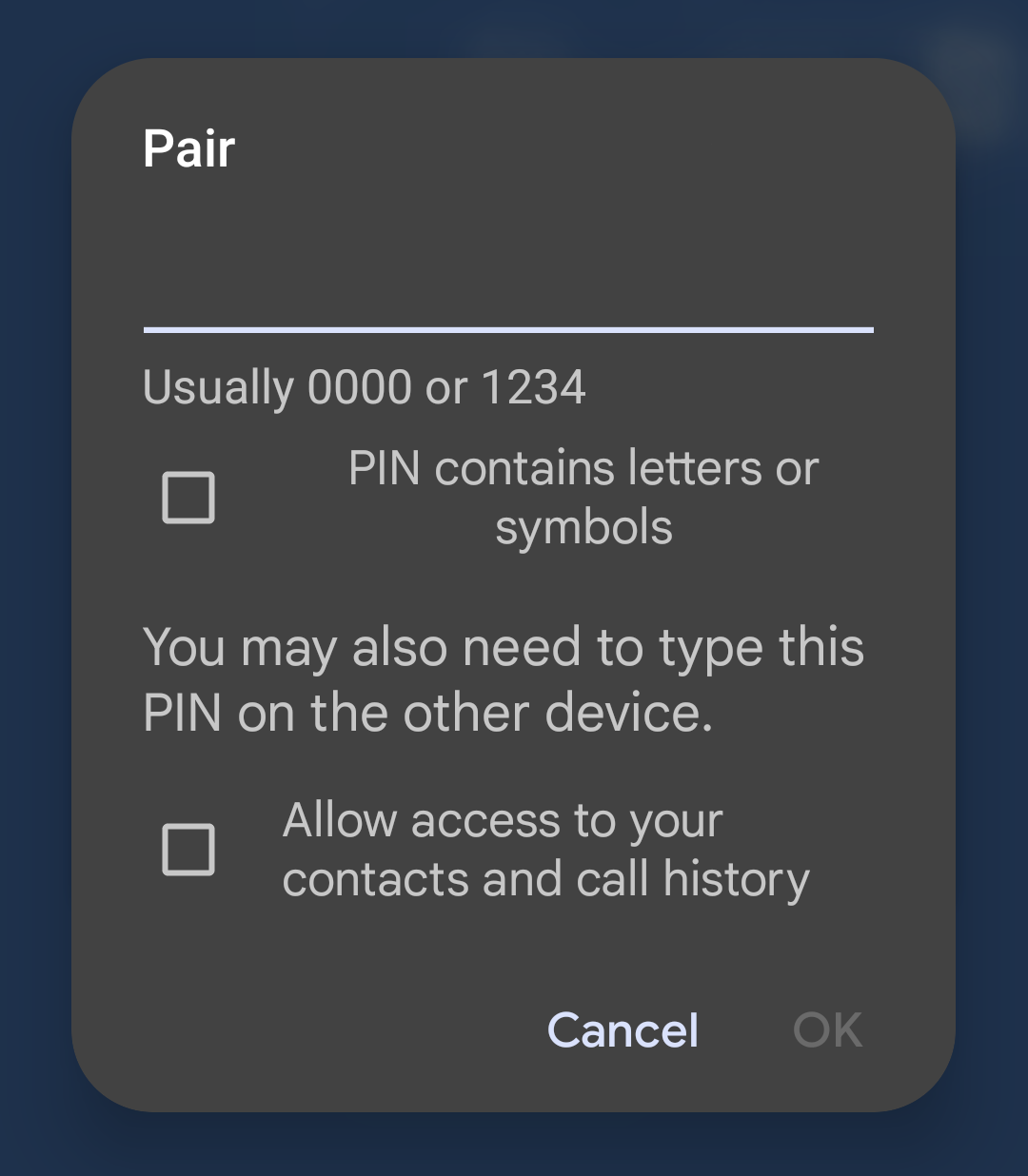
The following steps are necessary to successfully connect the Multi HS19 Solar via Bluetooth and the VictronConnect app:
|
|
4.2. Overview page
The main overview page provides at-a-glance information of the Multi HS19 Solar. It is divided into four tabs:
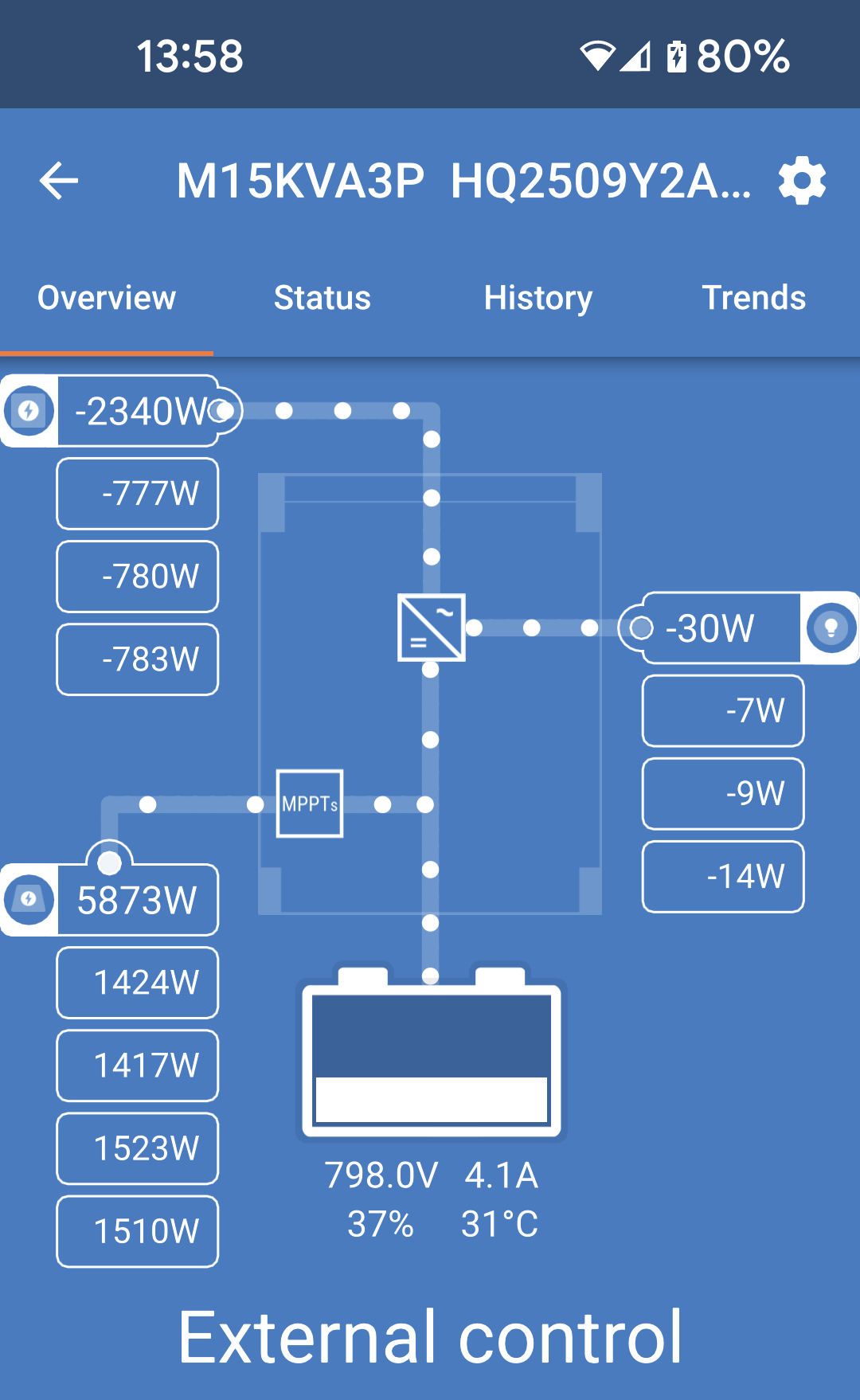
Overview: Instant readout of the basic state of the solar power yield, AC input and AC output.
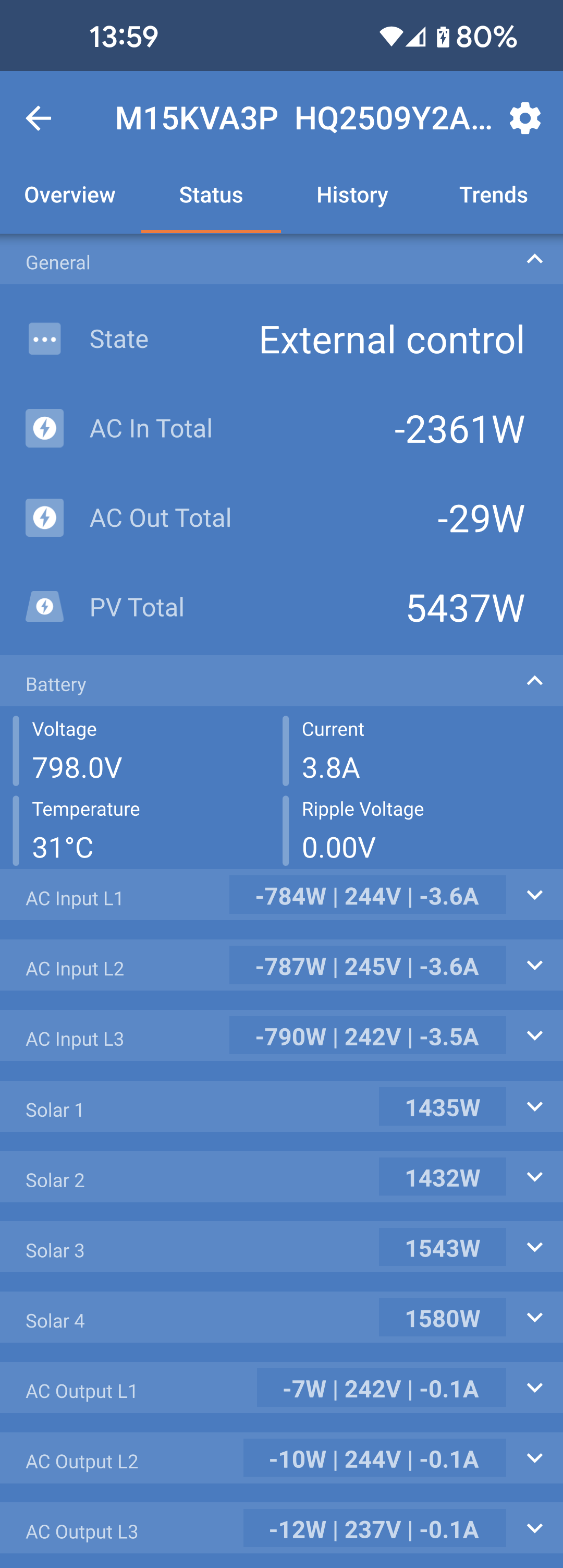
Status: Instant readout of the basic state of the Multi HS19 Solar.
History: View up to the last 30 days of solar and battery data.
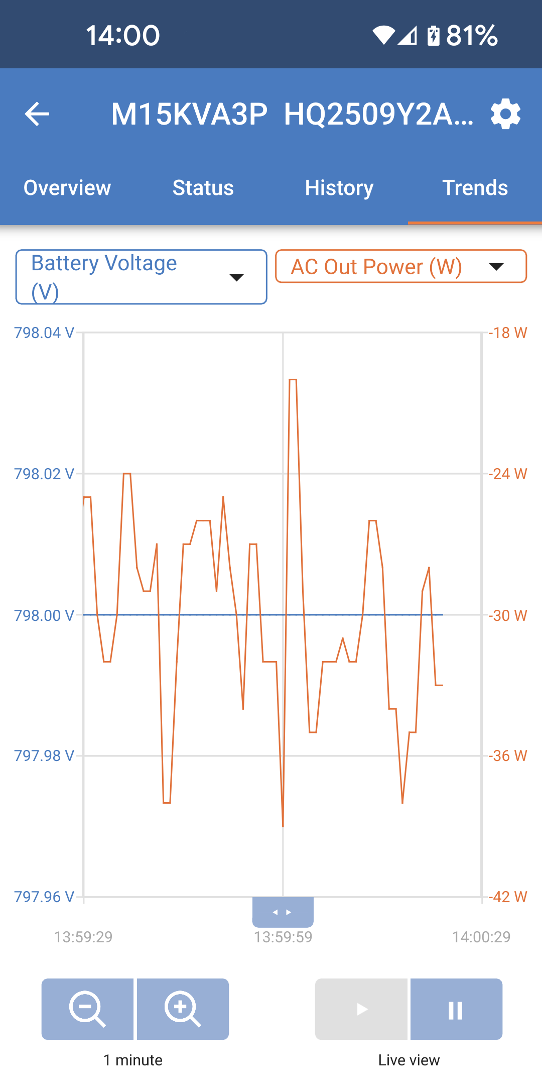
Trends: Review current trend data.
Overview:
|
|
Status tab: The status tab provides more detailed information than the overview tab. TipSome fields shows limited information at a glance. For more detailed information, tap the little down arrow at the right hand side of each field. Each field can be collapsed again to reduce clutter.
|
|
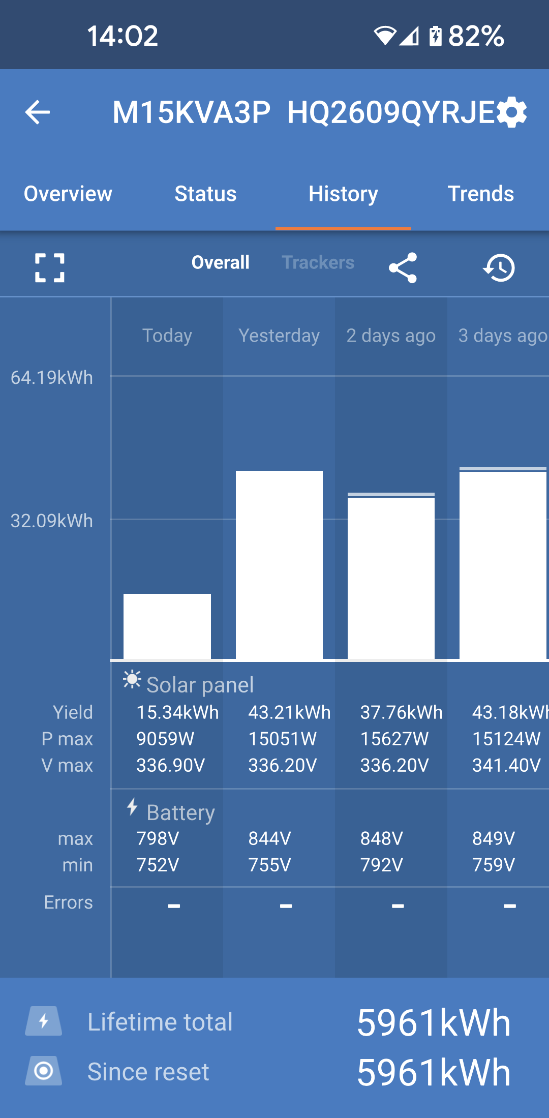
History tab: Up to 30 days of historical data is displayed. Overall Within the History tab, the default view show the Overall data.
TipTap the fragmented square icon in the top left of the graph area to rotate the graph. This will allow you to see a wide view of the graph with more days displayed at once. |
|
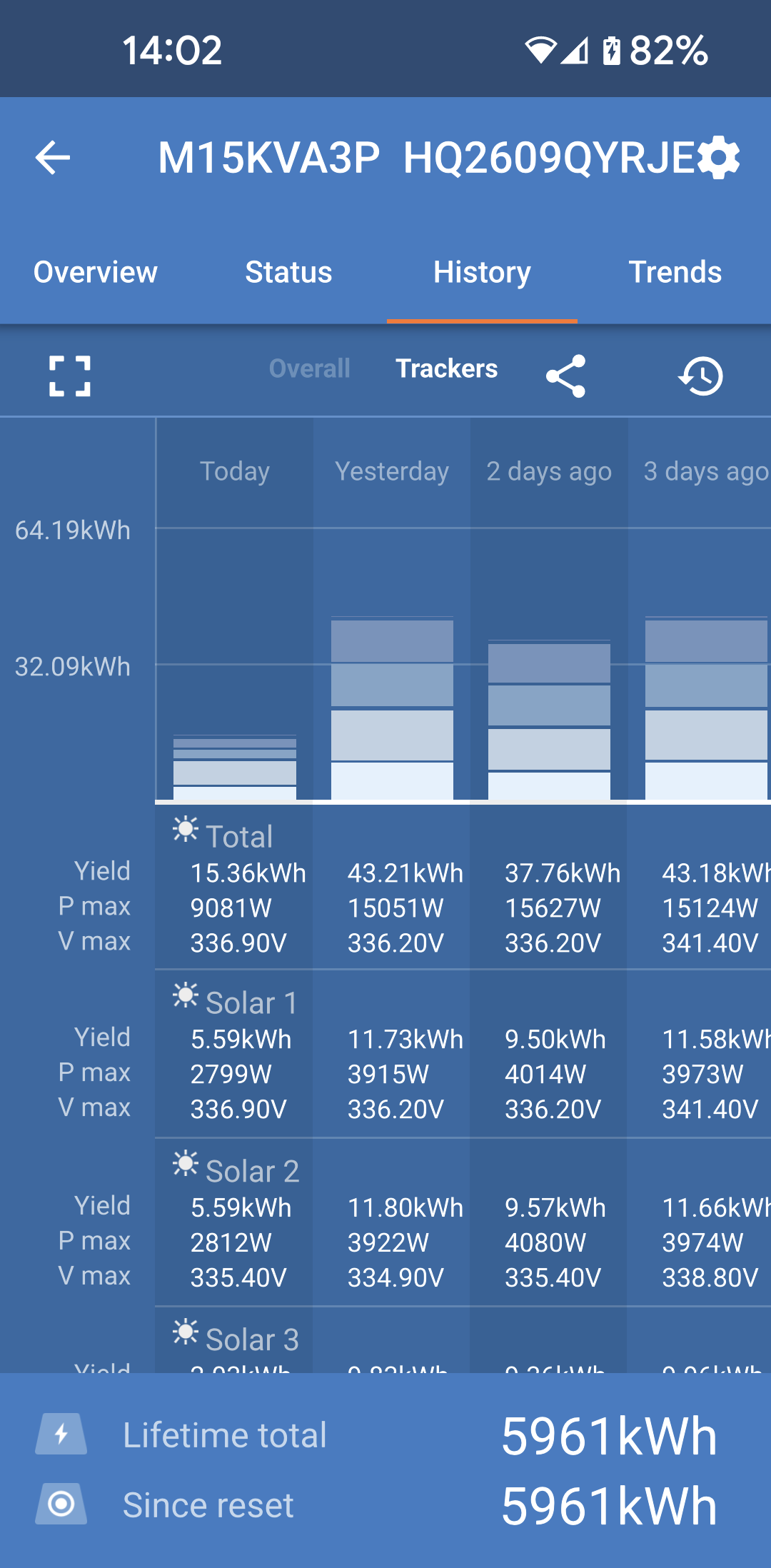
Trackers Also within the History tab, you can tap on the Trackers view to see the historical data of each of the four PV trackers. |
|
Trends tab:
|
|
4.3. Settings
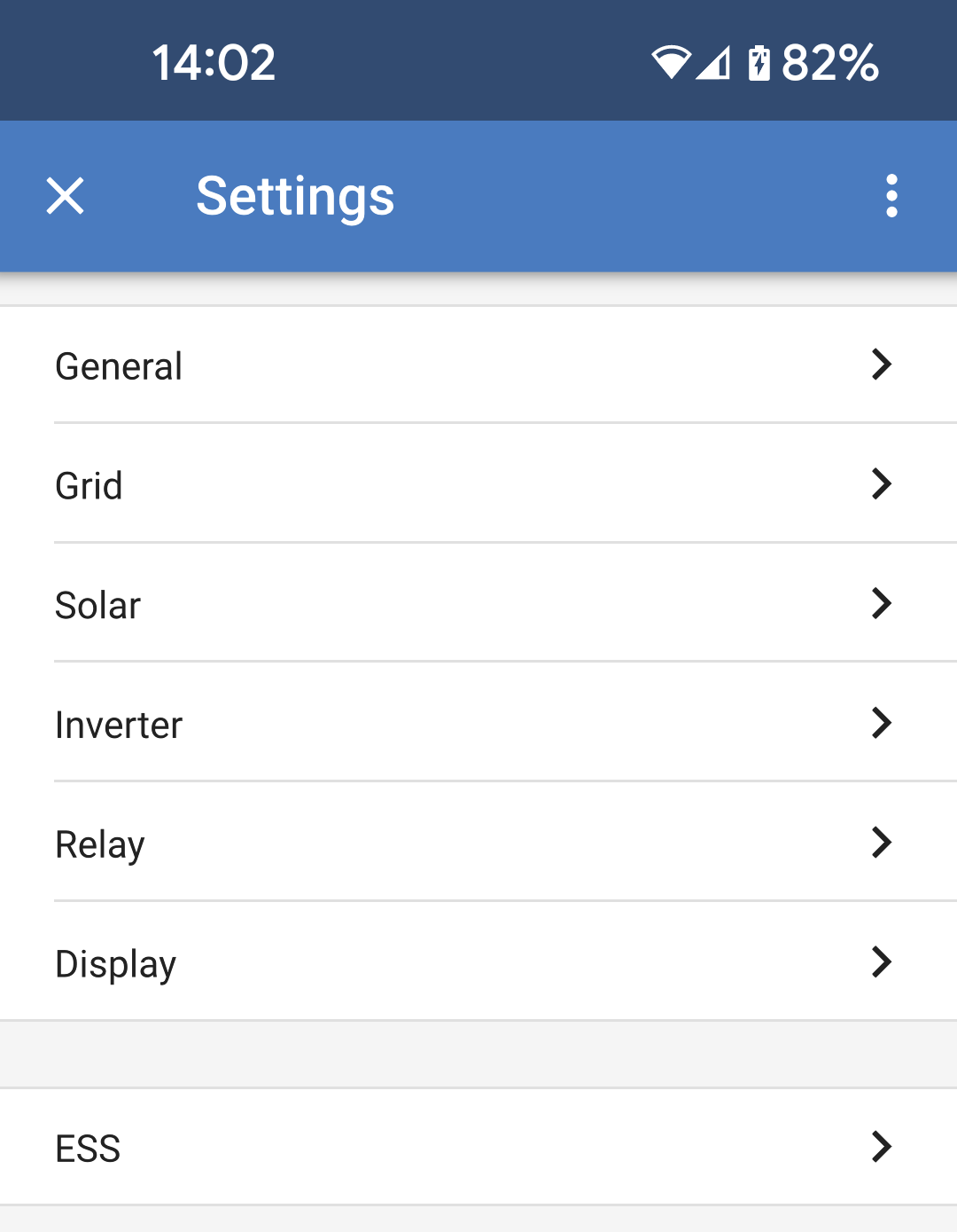
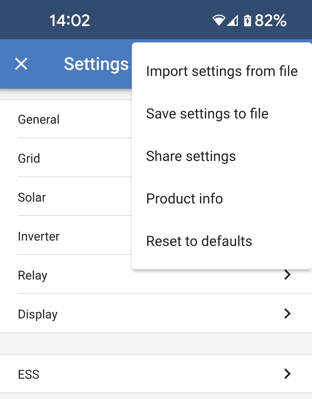
The Settings menu is accessible by pressing the cog wheel from the top right of the Overview page.
The following menu options are available:
|
|
Tap the three vertical dots in the top right corner of the settings page to perform the following actions:
|
|
4.4. Product info
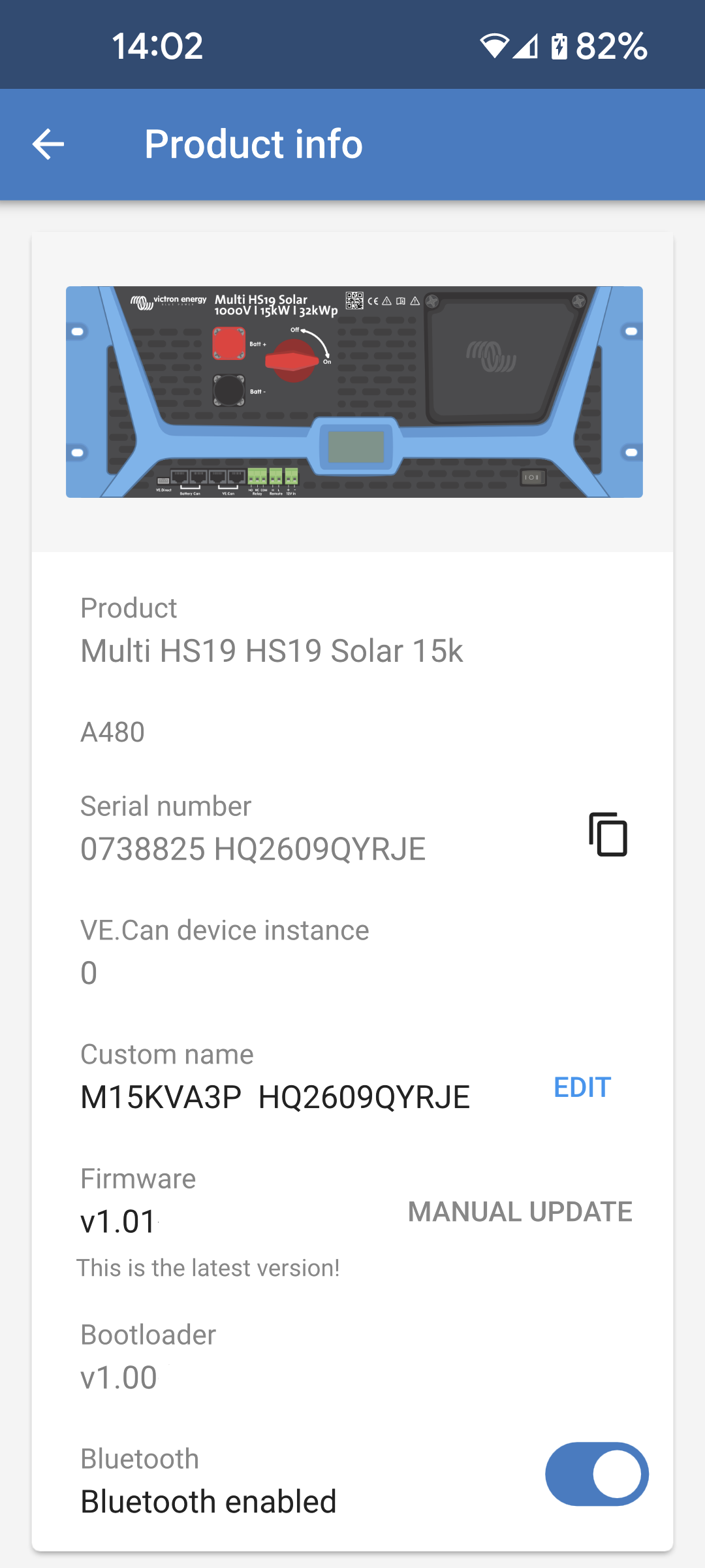
To get to the Product info page, tap the 3 vertical dots icon from the Settings page.
|
|
4.5. General
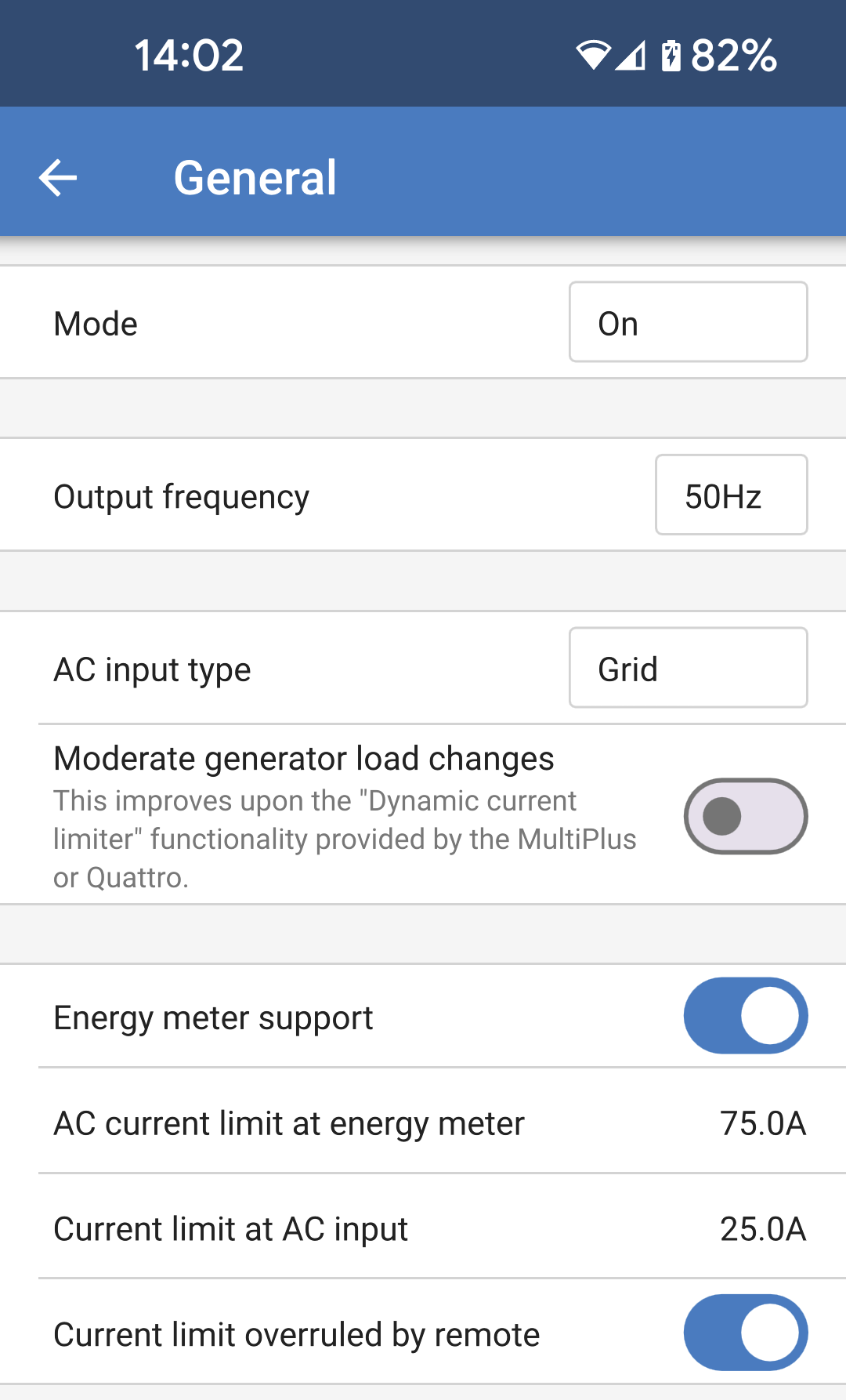
Use the General settings to configure the following:
|
|
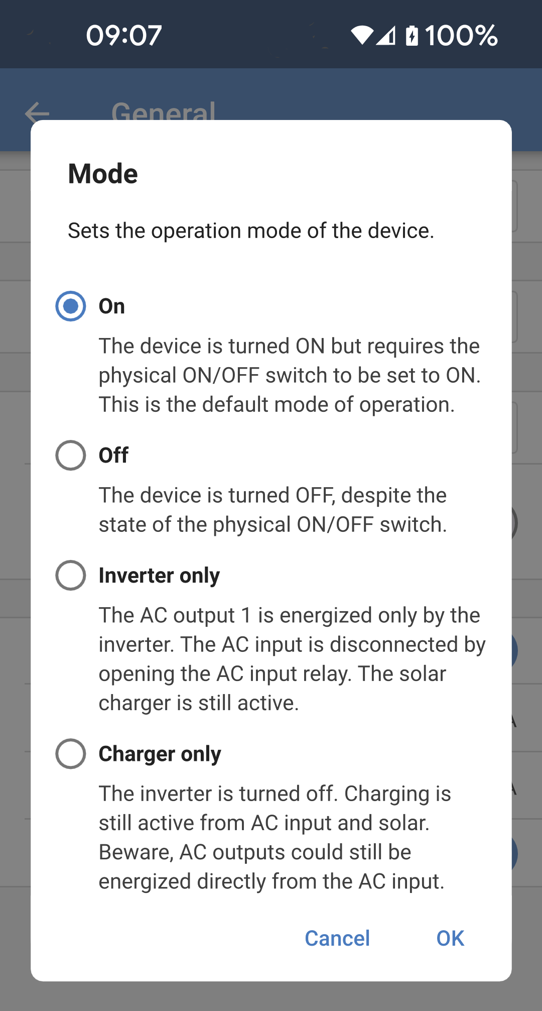
Mode The following options are available from the pop up menu:
|
|
4.6. Grid
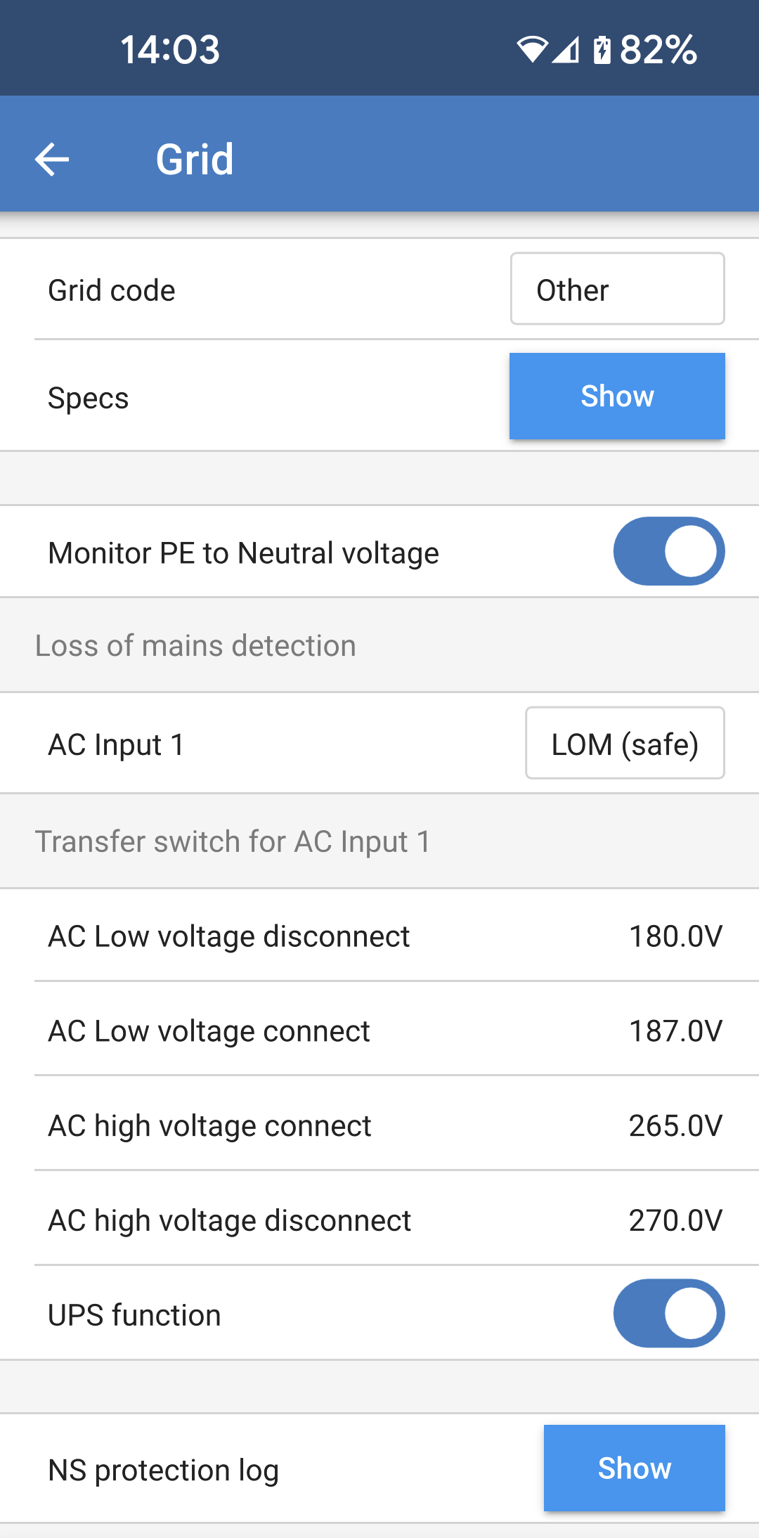
The grid settings page offers selection of a regional grid code and to adjust the AC input voltage limits.
Loss of mains detection: Most of these settings are typically greyed out and are intended for informational purposes only. The values are defined by the selected grid code. The below settings allow upper and lower AC input disconnection levels to be set. If the AC input voltage goes outside of these limits, then it will be disconnected and not passed through to the AC output. When the AC input is disconnected then, when the operation mode is set to "On," the inverter will provide power to the AC output.
|
|
4.7. Solar
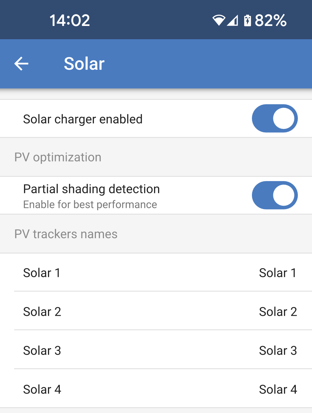
This page allows setting the Partial shading detection algorithm and giving each tracker a custom name.
PV Optimization:
PV trackers names:
PV trackers visibility:
|
|
4.8. Inverter
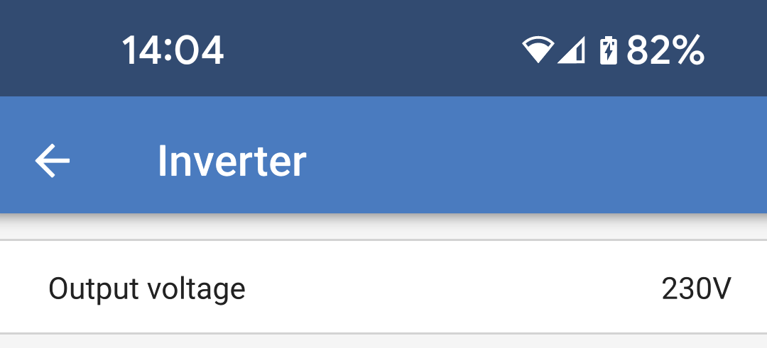
Change settings related to the inverter here.
|
|
4.9. Relay
A programmable relay is available in the Multi HS19 Solar. The contacts are accessible via the pluggable terminal block on the front panel. |
|
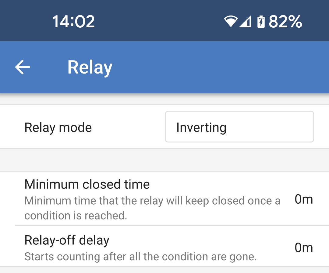
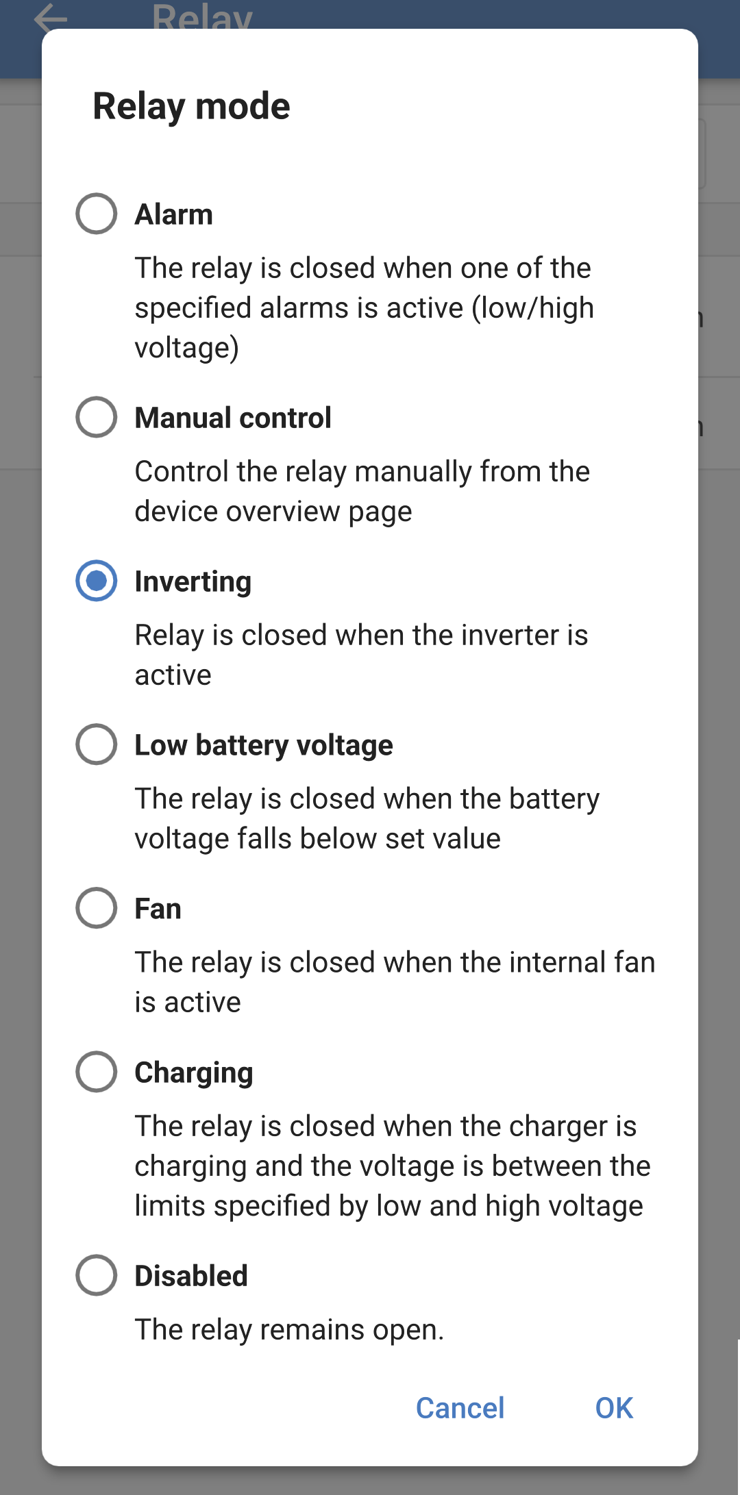
One of several relay modes can be selected from the list:
|
|
4.10. Display
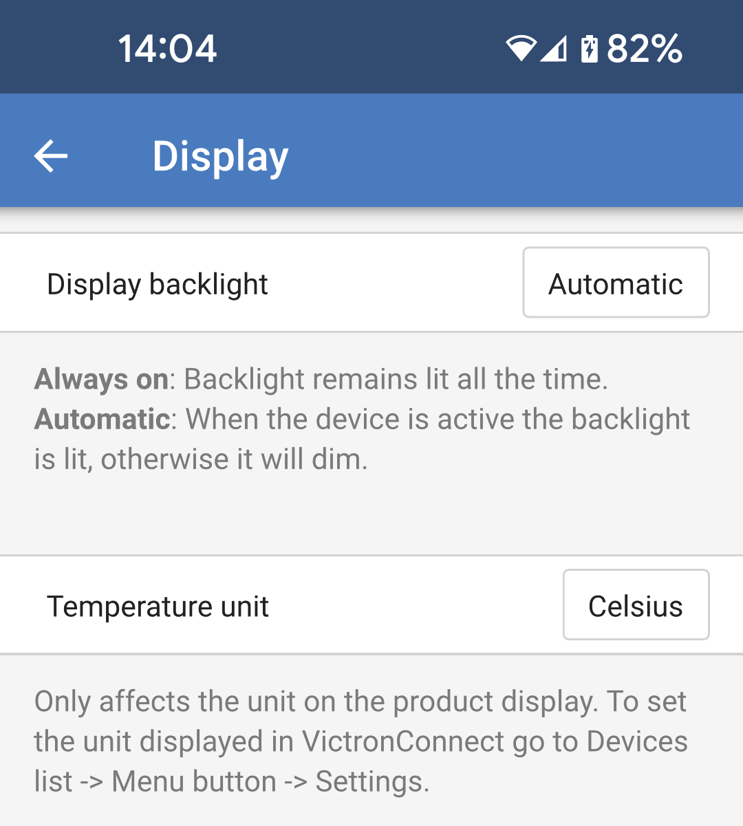
These settings define the behaviour of the front panel LCD backlight and the temperature unit that it will display.
|
|
4.11. ESS
In some cases the user may want to only use the AC input to charge the battery when necessary, and instead allow the batteries to discharge to provide for the loads and recharge from solar.
To enable this flexibility there are several possible configuration options.
The ESS settings are available out-of-the-box without the need to install an assistant.
ESS relies on an AC input being present, so it does not provide useful functionality in an off grid system.
Note
The ESS settings for the can only be changed using VictronConnect as shown below.
There is currently limited functionality from the ESS menu of a GX device.
There are currently no ESS controls from VRM.
The factory default operation when an AC input is connected to a is that the charger will begin charging the batteries up to the maximum AC input current and charge current limits. We call this factory default mode "Keep batteries charged."
|
|
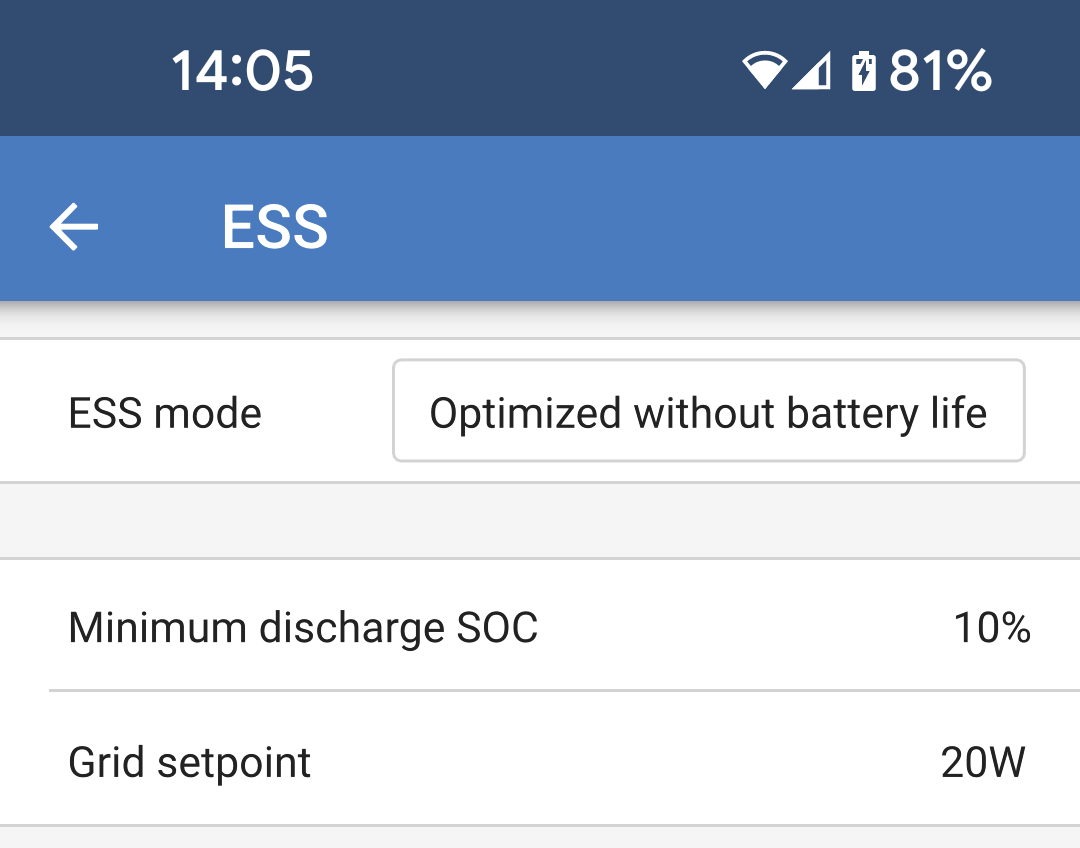
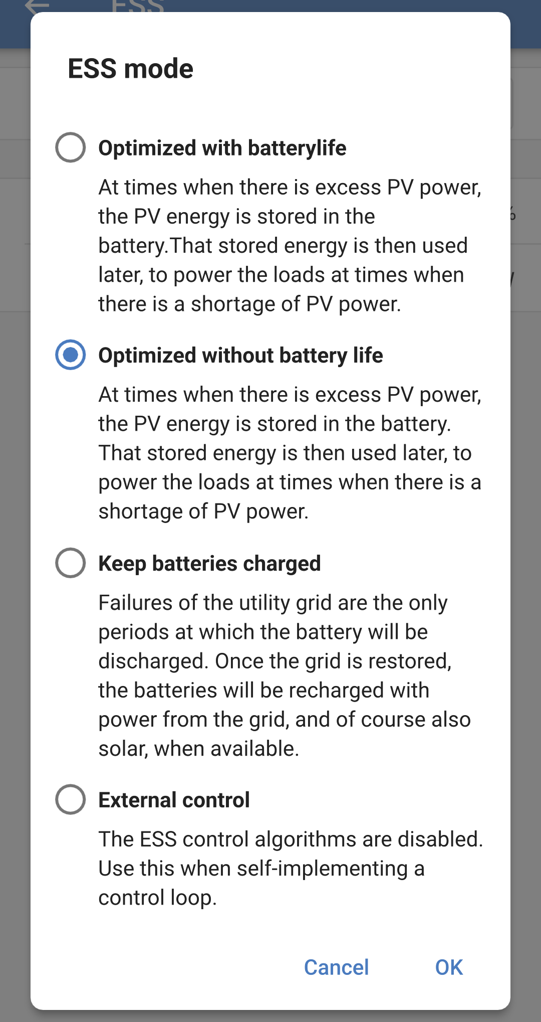
From the ESS mode pop box there are four options to choose from.
|
|