3. Installation
3.1. Mounting
| The Multi HS19 Solar is a 19" rack mountable unit. It is intended to be installed horizontally in a standard 19" rack mounting cabinet. The cabinet should allow unobstructed air flow through the Multi HS19 Solar from the front to the back. It's advisable to leave at least a 1U space above and below the unit to aid in cooling. If components within the cabinet are in contact with one another they'll exchange unwanted heat between them. To ensure a trouble free operation of the Multi HS19 Solar, it must be used in locations that meet the following requirements: a) Avoid any contact with water. Do not expose the Multi HS19 Solar to rain or moisture. b) Install the Multi HS19 Solar in a standard 19" cabinet, with a 1U clearance above and below it. c) The Multi HS19 Solar must be installed in a non-flammable cabinet and the construction materials surrounding the installation should also be non-flammable. d) Do not place the Multi HS19 Solar in direct sunlight. Ambient air temperature should be between 0°C and 60°C (humidity 95% non-condensing). e) Do not install the Multi HS19 Solar in an environment where the air could be contaminated with particulate matter such as soot, dust or salt. For example, conductive soot from the exhaust of a diesel generator could be drawn into the enclosure and cause short circuits inside it. f) Do not install the Multi HS19 Solar where flammable or corrosive gases or vapours could come near the installation. g) Do not obstruct the airflow through the Multi HS19 Solar. The cabinet should allow unobstructed air flow through the Multi HS19 Solar from the front to the back. h) If the Multi HS19 Solar is installed in an area used for general storage, ensure that no flammable materials such a cardboard boxes are stored close to the installation. Ensure that the end user is aware of these requirements. | |
| The Multi HS19 Solar contains potentially dangerous voltages. It should only be installed under the supervision of a suitable qualified installer with the appropriate training, and subject to local requirements. Please contact Victron Energy for further information or necessary training. | |
| Excessively high ambient temperature will result in the following:
Never position the appliance directly above lead-acid batteries. | |
| For safety purposes, the Multi HS19 Solar should be installed in a heat-resistant environment. You should prevent the presence of: e.g. chemicals, synthetic components, curtains or other textiles, etc., in the immediate vicinity. | |
| Never connect batteries directly to the Multi HS19 Solar. Always ensure that adequate circuit protection is installed between the batteries and the Multi HS19 Solar. |

Warning
The Multi HS19 Solar is designed for horizontal mounting only. Vertical mounting has not been tested or validated, and may affect thermal performance and mechanical reliability. Vertical installation is therefore not supported.
High DC voltages are supplied to the Multi HS19 Solar when a connected PV array is exposed to light.
PV modules must have an IEC 61730 Class A rating.
Ground the frame of the PV array following local regulations.
All disconnection means for batteries, PV isolators and AC circuit breakers must remain accessible at all times. A circuit breaker rated at 32A or less is required for the AC input.
If local installation regulations require an external Residual Current Device (RCD), a separate type A RCD with rated residual operating current of 300mA or higher may be installed at AC input. When required by local regulations, a type B RCD may also be used, although it is not required by Victron Energy.
This is a safety class I product (supplied with a protective grounding terminal) and is intended to be used in a TN or TT earthing system. Its AC input and/or output terminals and/or grounding point on the product must be provided with an uninterruptible grounding point for safety purposes. In a fixed installation, an uninterruptible grounding can be secured by means of the grounding wire of the AC input. Otherwise the casing must be grounded. Whenever it is likely that the grounding protection has been damaged, the product must be turned off and secured against unintended operation; please contact qualified service staff. The Multi HS19 Solar is provided with a ground relay that automatically connects the Neutral output to the chassis if no external AC supply is available. If an external AC supply is provided, the ground relay will open before the input safety relay closes. Follow the local national wiring standards, regulations and installation instructions for electrical work.
Use the VictronConnect App for configuration, control and view the status of the Multi HS19 Solar. You can view the current firmware version and preform firmware updates using VictronConnect. Operational status and firmware version is also displayed on the front panel LCD.
The VE.Can port is used for other VE.Can connected products such as an external energy meter or a GX device for remote monitoring and fault indication.
3.2. Connection overview
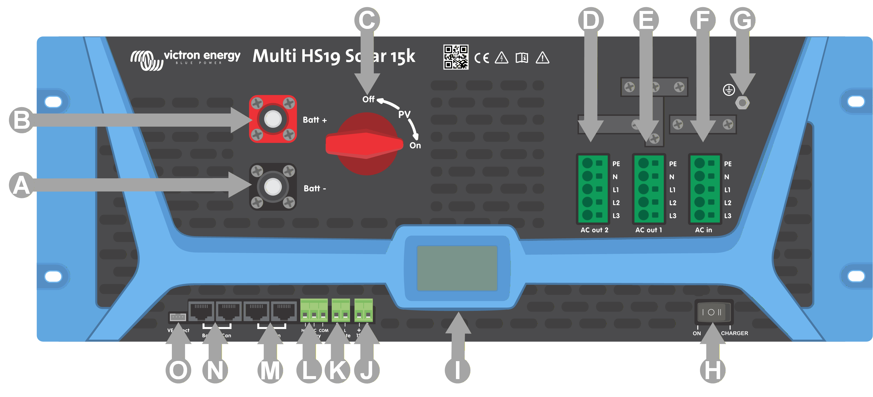
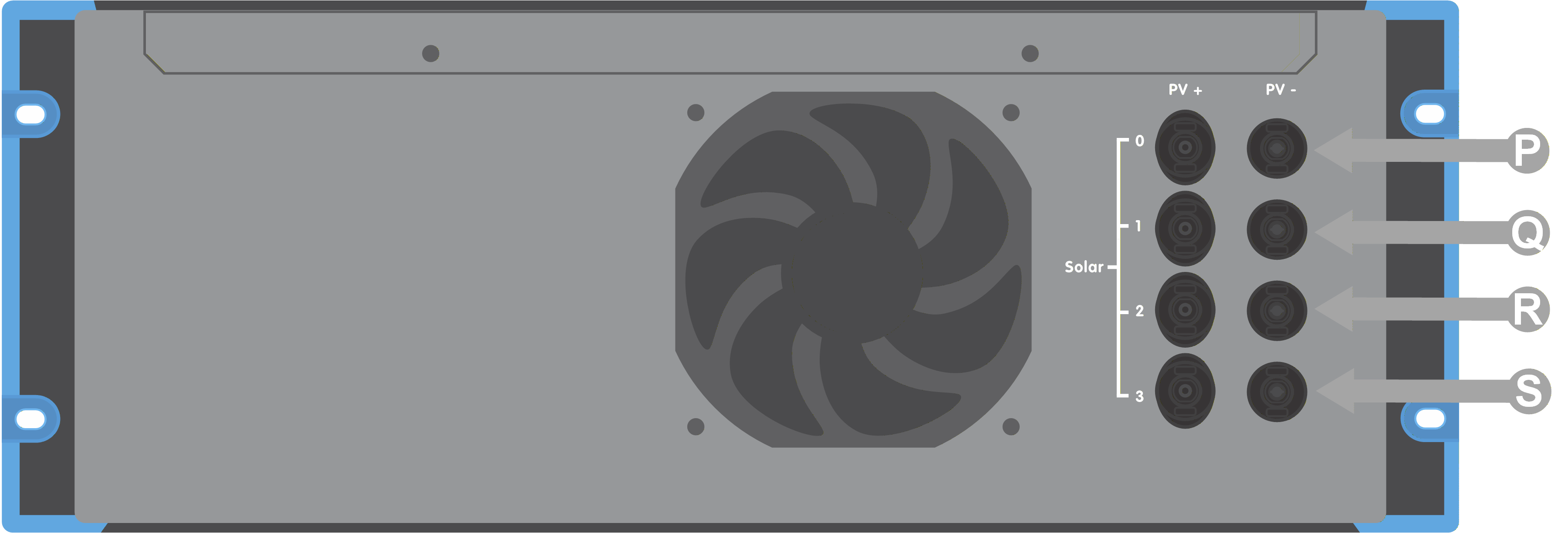
The illustration shows the front and rear panel connectors with a description for each one in the table below.
|
|
Letter | Name | Description |
|---|---|---|
A | Battery - | Battery negative connector |
B | Battery + | Battery positive connector |
C | PV Switch | PV disconnect switch. Disconnects all four strings. |
D | AC Out 2 | AC Output 2 |
E | AC Out 1 | AC Output 1 |
F | Ac In | AC Input |
G | Chassis ground | Chassis grounding terminal |
H | Power Switch | Power on / off / charger only switch |
I | Display | User LCD display |
J | 12V in | 12V input for keep=alive circuit |
K | Remote H / L | Remote on / off terminals |
L | Relay | Programmable relay contacts |
M | VE.Can | VE.Can Canbus connection pair |
N | Battery Can | Battery BMS Canbus connector pair |
O | VE.Direct | VE.Direct connector |
P | PV 0 | PV array 0 MC4 connectors |
Q | PV 1 | PV array 1 MC4 connectors |
R | PV 2 | PV array 2 MC4 connectors |
S | PV 3 | PV array 3 MC4 connectors |
3.3. Solar array configuration
Caution
Always use genuine Staubli MC4 connectors for the PV connections to the Multi HS19 Solar.
Connectors from other brands may not be fully compatible with the Staubli connectors on the Multi HS19 Solar.
Warning
Do not hot-plug the PV connections. Ensure that the Multi HS19 Solar is switched off before connecting or disconnecting PV arrays.
The Multi HS19 Solar is built using Staubli MC4 connectors. There are many other brands available, but some manufacturing variations mean that they may make poor contact and cause excessive heat. There are also inferior brands on the market which will likely cause problems.
Caution
The maximum rated voltage of the solar charger is 600V. A PV overvoltage event will damage the solar charger. This damage is not covered by warranty.
There is a maximum short circuit current per tracker. Check the technical specifications section for details.
Warning
BEWARE that the product warranty will be void if a PV array with a short circuit current larger than rated is connected in reverse polarity.
Caution
The Multi HS19 Solar must keep the individual tracker inputs isolated from each other. That means one solar PV array per input, do not attempt to connect a single array to multiple tracker inputs.
When the MPPT switches to float stage it reduces battery charge current by increasing the PV Power Point voltage.
The maximum open circuit voltage of the PV array must be less than 600 V when the battery is at float voltage.
3.4. Battery connections
In order to utilize the full capacity of the product, batteries with sufficient capacity and battery cables with sufficient cross section should be used. The use of undersized batteries or battery cables will lead to:
Reduction in system efficiency
Unwanted system alarms or shutdowns
Permanent damage to the system
The battery connection terminals on the Multi HS19 Solar are Amphenol SurLok Plus.
Warning
The battery is not galvanically isolated from the AC input, AC output or Solar PV.
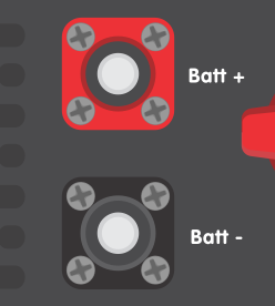 |
Connector Designation | Colour | Orientation | Amphenol part number |
|---|---|---|---|
Battery positive | Red | Right Angle | SLPPA25BSR |
Battery positive | Red | Straight | SLPIPA25BSR |
Battery negative | Black | Right Angle | SLPPA25BSB |
Battery negative | Black | Straight | SLPIPA25BSB |
Warning
Consult battery manufacturer recommendations to ensure the batteries can take the total charge current of the system. Decision on battery sizing should be made in consultation with your system designer.
3.5. AC connections
The AC connection terminal blocks can be found on the front panel.
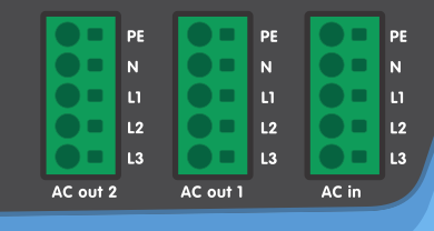 |
The AC connector block is a push-in spring connector.
Conductor insulation should be stripped to expose 15mm of bare conductor.
Push the conductor into the round hole of the terminal block position. Multi-stranded conductors may require a small screwdriver to be inserted into the square hole to release the spring tension which will ease insertion of the conductor.
Refer to the technical specifications page for information about cable cross sectional area.
Warning
DO NOT reverse the polarity of the neutral and line conductors when connecting AC cabling.
Warning
Galvanic isolation is NOT provided between AC output and PV DC input.
It is possible for high voltage to be present on the PV DC input connectors even if the PV array is disconnected or at night. Ensure that the Multi HS19 Solar is switched off before working on the PV array or wiring.
Always use DC tolerant earth leakage circuit breakers in the AC circuits according to local regulations.
AC output 1 will be active when the Multi HS19 Solar is running on battery. Both AC outputs will be active when the AC input is available.
The AC input must be protected by a fuse or circuit breaker rated according to the model of Multi HS19 Solar, and cable cross-section must be sized accordingly. If the input AC supply is rated at a lower value, the fuse or circuit breaker should be down sized accordingly.
3.6. Auxilary connections
VE.Direct
This can be used to connect a PC/laptop to configure the inverter with a VE.Direct to USB accessory. Can also be used to connect a Victron GlobalLink 520 to allow for remote data monitoring.
VE.Can
Used to connect to a GX Device, and/or daisy-chain communications to other VE.Can compatible products.
Battery Can
Connect to the Canbus port of the battery system.
Bluetooth
Used to connect to the device via VictronConnect for configuration.
Remote on / off connector
The remote on/off connector has two terminals, the “Remote L” and the “Remote H” terminal.
The Multi HS19 Solar ships with the remote on/off connector terminals connected to each other via a wire link.
Note that for the remote connector to be operational, the main on/off switch on the Multi needs to be switched to “on”.
The default function of the remote on/off connector is to remotely switch the unit on or off.
The unit will switch on if “Remote L” and the “Remote H” are connected to each other (via a remote switch, relay or the wire link).
The unit will switch off if “Remote L” and the “Remote H” are not connected to each other and are free floating.
The unit will switch on if “Remote H” is connected to battery positive (Vcc).
Programmable relay
Programmable relay which can be set for general alarm, DC under voltage or genset start/stop function. See the Technical specifications section for contact ratings.
12V input
This input is used to keep the Multi HS19 Solar alive and to allow for black start situations.