2. Installation
The GX IO-Extender 150 works with all GX devices but it is best used in combination with Node-RED. Node-RED is not supported on all GX devices. Refer to the Venus OS Large documentation for more information about which GX devices support Node-RED.
To install the GX IO-Extender 150:
Use the DIP switches on each bank of 4 digital I/Os to set them as 4 inputs or 4 outputs (ON = output, OFF = input). Note that changes to the DIP switches require a power cycle of the device.
Connect the USB cable of the GX IO-Extender 150 to an available port on the GX device. Note that the USB-port closest to the HDMI port on some Cerbo GX models may not be suitable for this purpose. Please refer to the GX device manual for more information.
Confirm the GX IO-Extender 150 is powered via the USB connection.
Use the remote console on the GX to review the additional relays, PWMs and digital inputs or outputs available on the system.
2.1. Hardware
All ports on the GX IO-Extender 150 are equipped with blue or orange LEDs to indicate their current state.

Note
The digital outputs are intended for signalling purposes only and must not be used to switch loads directly. The PWM outputs are suitable for applications such as LED dimming, motor speed control, and similar applications.
Important
Technical Note: Always check the maximum ratings for each output type in the datasheet of the GX IO-Extender 150.
Digital I/O
The digital I/O ports are split up in 2 groups of 4 ports which are intended for signalling rather than directly switching loads. Each group can be configured as either input or output using the dip switches in between the ports.
Mode ON = output
Mode OFF = input
Important
After changing the mode, reboot the GX or unplug and replug the USB cable to power cycle the device for the changes to take effect.
Important
Technical Note: The digital outputs can source 4 mA max. When driving 4 mA, the voltage drop across the internal series resistor (560 Ω) is 2,24 V, which leaves only 2,76 V @ 4 mA for the output signal. Therefore, a driver like a transistor or FET is required to switch a relay with a digital output.
PWM
The PWM ports are to be connected between GND and signal. The PWM port indicator LEDs are illuminated when the port is switched on, and the intensity of the illumination reflects the current status of the PWM slider value.
Bistable Relays (Relay 1 & 2)
The bistable (latching) relays on the GX IO-Extender 150 work differently from the monostable (non-latching) relays found on devices like the Cerbo GX.
A monostable relay has a default state determined by its wiring:
NO (Normally Open): Load is OFF by default, ON when relay is powered.
NC (Normally Closed): Load is ON by default, OFF when relay is powered.
A bistable relay has two stable positions — A and B — that stay fixed even when power is lost. The relay switches between them with a short pulse, using no power to maintain either state. The active position is shown by the LED:
Blue LED: Position A active
Orange LED: Position B active
Common examples
Mimicking a NO monostable relay
To replicate the behaviour of a normally open relay:
Connect your power source to COM.
Connect your load to Terminal A.
Leave Terminal B disconnected.
Configure the relay in Toggle mode.
In position A (blue LED), the load is powered. In position B (orange LED), the load is disconnected.
Tip
If the load should be OFF after a power cycle, set the relay to position B before shutdown.
Switching between “GREEN” and “RED” indicator lights
The relay can switch power between two circuits, for example:
COM connected to your power source.
Terminal A wired to a “GREEN” indicator light.
Terminal B wired to a “RED” indicator light.
Configure the relay in Toggle mode.
When in position A (blue LED), the GREEN light is active. When switched to position B (orange LED), the RED light is active.
Momentary operation: Siren and “All OK” light
For momentary operation with default feedback:
COM connected to your power source.
Terminal A wired to a siren.
Terminal B wired to an “All OK” light.
Configure the relay in Momentary mode.
In its resting state (position B, orange LED), the “All OK” light is illuminated. When the momentary switch is activated, it briefly switches the relay to position A, sounding the siren. Once the momentary pulse ends, the relay returns to position B, and the “All OK” light comes back on.
Solid Switch
The solid switch on the GX IO-Extender 150 is designed to electronically switch the positive side of a DC circuit, with no mechanical contacts.
Bat+ → Connect to the positive terminal of your battery or DC power supply.
Load → Connect to the positive side of your device or load.
Bat- → Connect to the negative terminal of your battery or DC power supply.
The negative side of your load connects directly to Bat- (or a shared ground).
Configure the relay in Toggle mode.
This setup allows the solid-state relay to switch your load on and off by making or breaking the positive side of the circuit electronically.
If the solid switch is configured as momentary, it will only switch the load on for as long as the control signal remains active.
2.2. Software
Node-RED is a low-code programming environment for event-driven applications (https://nodered.org). See the installation manual for more information on the Node-RED and GX device combination: https://www.victronenergy.com/live/venus-os:large.
The following 4 steps are needed to get Node-RED up and running on your system:
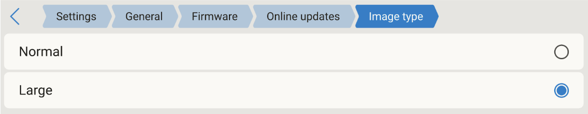
Set the firmware image type to Large and update the firmware
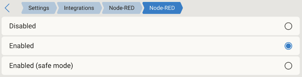
Once rebooted in the large image, enable Node-RED
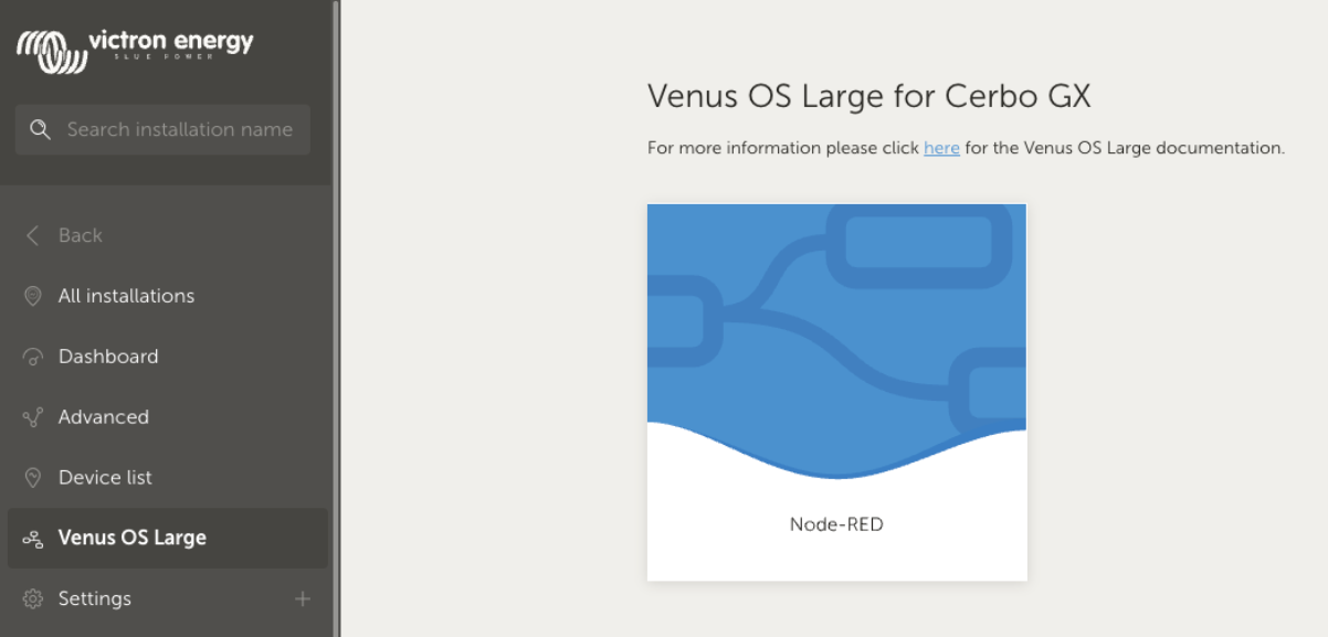
Open the Node-RED dashboard via either VRM under the Venus OS Large menu option or locally via https://venus.local:1881/
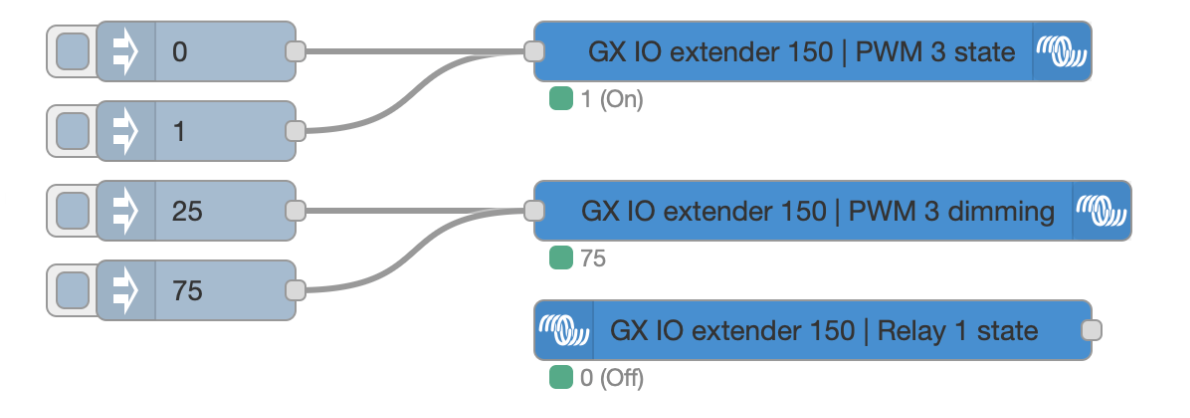
Pull in the Switch and Switch control node and control the GX IO-Extender 150. These nodes are part of the node-red-contrib-victron package that comes pre-installed with the Venus OS Large image.