5. Appendix
5.1. Available Control Paths
The device announces itself under the dbus service com.victronenergy.switch.<serial> and exposes the paths as described in this appendix. Check https://github.com/victronenergy/venus/wiki/dbus#switch for the meaning and usage of any additional paths.
5.1.1. Digital Inputs
Digital inputs need to be coupled to a function first, before you can use them. This needs to be done in the console as described above.
Set the type of a digital input with
com.victronenergy.digitalinputs/Devices/<input>Type
0 = Disabled
1 = Pulse meter
2 = Door
3 = Bilge pump
4 = Bilge Alarm
5 = Burglar Alarm
6 = Smoke Alarm
7 = Fire Alarm
8 = CO2 Alarm
9 = Generator
When set to pulse meter, the service com.victronenergy.pulsemeter.<input> will show up. Setting it to any of the other functions will create a service of type com.victronergy.digitalinput.<input>.
Pulsemeter paths
/Count: number of counted pulses
Generic digital input paths
/State: State of the input
5.1.2. Digital Outputs
Note that these paths will only be present when the corresponding IO is set to output (with the DIP switches).
/SwitchableOutput/output_1/State (0=Off, 1=On)
/SwitchableOutput/output_2/State (0=Off, 1=On)
/SwitchableOutput/output_3/State (0=Off, 1=On)
/SwitchableOutput/output_4/State (0=Off, 1=On)
/SwitchableOutput/output_5/State (0=Off, 1=On)
/SwitchableOutput/output_6/State (0=Off, 1=On)
/SwitchableOutput/output_7/State (0=Off, 1=On)
/SwitchableOutput/output_8/State (0=Off, 1=On)
5.1.3. PWM Outputs
/SwitchableOutput/pwm_1/State (0=Off, 1=On)
/SwitchableOutput/pwm_1/Dimming (integer value from 0-100, representing percentage)
/SwitchableOutput/pwm_2/State (0=Off, 1=On)
/SwitchableOutput/pwm_2/Dimming (integer value from 0-100, representing percentage)
/SwitchableOutput/pwm_3/State (0=Off, 1=On)
/SwitchableOutput/pwm_3/Dimming (integer value from 0-100, representing percentage)
/SwitchableOutput/pwm_4/State (0=Off, 1=On)
/SwitchableOutput/pwm_4/Dimming (integer value from 0-100, representing percentage)
5.1.4. Relay Outputs
/SwitchableOutput/relay_1/State (0=Off, 1=On) - Bi-stable relay 0 = A, 1 = B
/SwitchableOutput/relay_2/State (0=Off, 1=On) - Bi-stable relay 0 = A, 1 = B
/SwitchableOutput/relay_3/State (0=Off, 1=On) - Solid switch load state
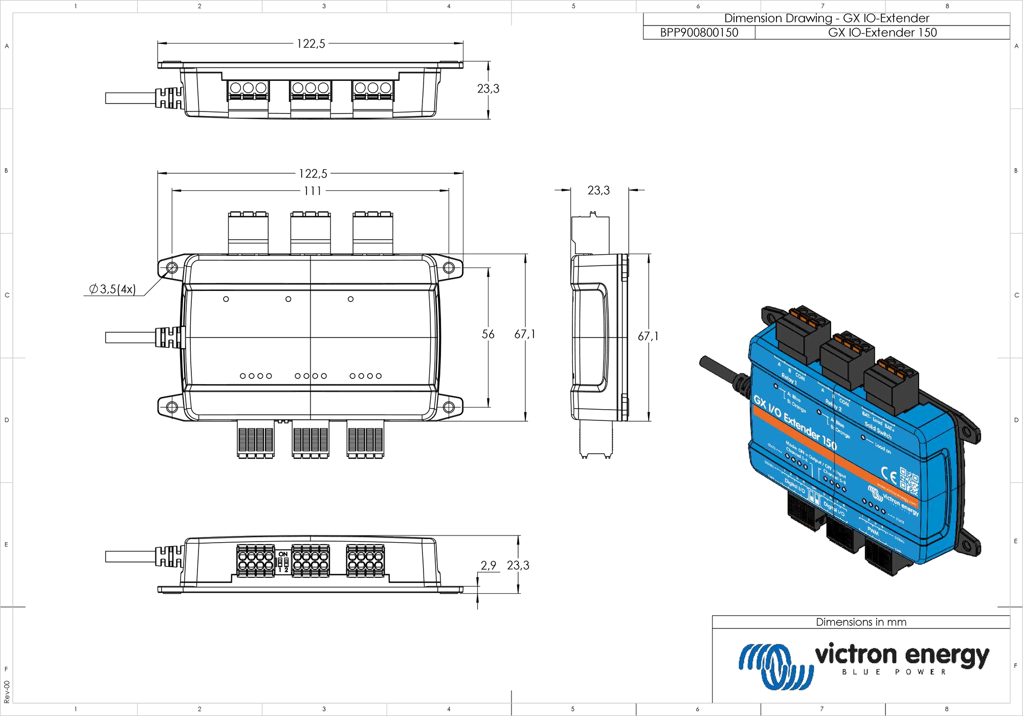
5.2. Enclosure dimensions