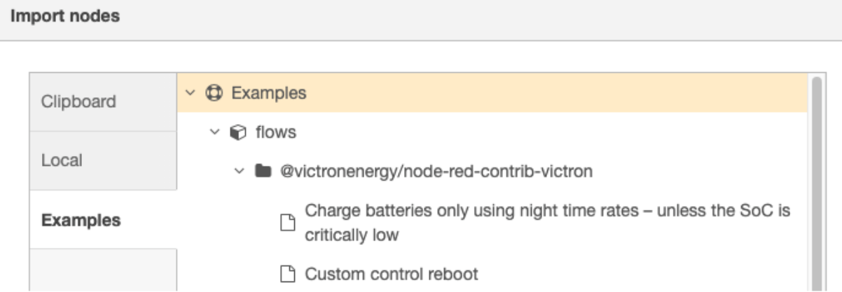
3. Example flows
These, and other, example flows can be imported via the Import option within Node-RED.
 |
Simple digital output control
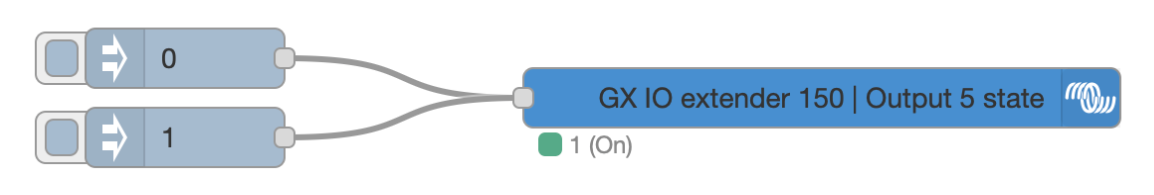 |
This example turns an output on and off with a button
Simple digital input control
First, the digital input must be configured to a type using the Settings > Integrations > Digital IO on the GX device, then select a digital input from the GX IO-Extender 150 and set a type.
Supported input types are:
Pulse meter N/A
Door alarm Open/Closed
Bilge pump On/Off
Bilge alarm Ok/Alarm
Burglar alarm Ok/Alarm
Smoke alarm Ok/Alarm
Fire alarm Ok/Alarm
CO2 alarm Ok/Alarm
Generator Running/Stopped
Touch input control
Once an input type has been selected, a Digital input node can be used to read the status of that input for further use in the flow.
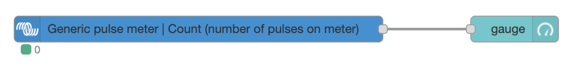 |
This example displays pulses read on a digital input using a gauge in Node-RED dashboard
Increase PWM
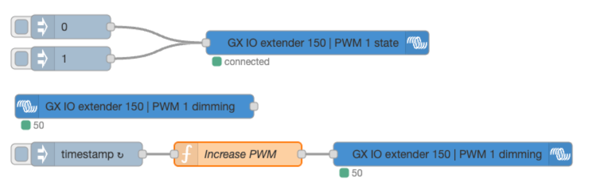 |
The top part of this flow is for switching on or off the PWM port using the PWM state parameter. Once the port is switched on, it will use whatever PWM value is set using the PWM dimming parameter. The input node reads the current value of the PWM port and stores that in the global Node-RED context.
The inject node injects a timestamp each second, which gets replaced by the current PWM value of the port, increased by 25. If the value is above 100, it resets back to 0.
Note that you may need to adjust the used Switch and PWM port in the function node to make it functional for you.