12. DVCC - Distributed Voltage and Current Control
12.1. Introduction and features
Enabling DVCC (under Settings → System Setup → Charge Control) changes the GX device from a passive monitor into an active system controller. The available DVCC features depend on:
The type of battery in use
The installed Victron components
Their configuration
Example 1 - Managed CAN-bus batteries:
When a managed CAN-bus BMS battery is connected, the GX device receives:
Charge Voltage Limit (CVL)
Charge Current Limit (CCL)
Discharge Current Limit (DCL)
These values are passed to connected inverter/chargers, solar chargers, and Orion XS DC-DC chargers, which then disable their own charging algorithms and follow the battery’s instructions directly.
Example 2 - Lead-acid batteries:
For lead-acid systems, DVCC enables:
A configurable system-wide charge current limit, where the GX device actively limits the inverter/charger if solar chargers are already operating at full output.
Shared Temperature Sense (STS)
Shared Current Sense (SCS)
These features enhance coordinated charging behaviour across the system.
This table shows the recommended settings for different battery types:
Lead-acid | VE.Bus BMS V1 Lithium | VE.Bus BMS V21) Lithium | VE.Bus BMS NG1) Lithium | Supported 3rd party managed batteries2) | |
|---|---|---|---|---|---|
1) DVCC must be enabled for the GX device to control the solar chargers, Inverter RS or Multi RS in a system with a VE.Bus BMS V2 or VE.Bus BMS NG. 2) Use the Battery Compatibility manual to see which parameters need to be set and which are set automatically. 3) In an ESS system the VE.Bus device is already synced with the solar chargers, so we recommend leaving SVS and SCS off. 4) For all other systems: If a BMV or SmartShunt is installed, we recommend enabling SVS and SCS. In all other cases, leave SVS and SCS disabled. 5) Solar Chargers, Inverter/Chargers, Multi RS, Inverter RS and Orion XS do not require wiring. All other loads and chargers must be wired and controlled via ATC/ATD. | |||||
Auto-config | No | No | No | No | 2) |
System charge current | Yes | Yes | Yes | Yes | 2) |
Should you enable SVS? | Yes | 3), 4) | 3), 4) | 3), 4) | 2) |
Should you enable STS? | Yes | No | No | No | 2) |
Should you enable SCS | Yes | 3), 4) | 3), 4) | 3), 4) | 2) |
Charge control method | N/A | N/A | N/A | N/A | 2) |
Wire ATC & ATD | N/A | Yes | 5) | 5) | 2) |
12.2. DVCC Requirements
Battery compatilibity
For CAN-bus connected batteries, refer to the relevant page in the Battery Compatibility manual to see if enabling DVCC has been tested with your battery type and is supported. → Only enable DVCC if it is explicitly listed as supported for your battery type.
⚠️ If DVCC is not mentioned in notes relating to your battery, do not enable it.
DVCC is fully supported and can be used without issue for:
Lead-acid batteries (Gel, AGM, OPzS, etc.)
Victron Lithium Smart with:
VE.Bus BMS
Lynx Ion + Shunt BMS
Lynx Ion BMS
Victron Lithium NG with:
VE.Bus BMS NG
For systems with the Lynx Smart BMS or Lynx BMS NG, DVCC is automatically enabled and cannot be disabled.
Firmware versions
Do not use DVCC if firmware requirements are not met.
During commissioning, always install the latest available firmware.
Once the system is running reliably, firmware updates are not required unless needed.
If issues occur, the first step should be to update firmware.
Required minimum firmware versions:
Victron product
Minimum firmware version
Multi/Quattro
422
MultiGrid
424
Multi RS, Inverter RS, MPPT RS
v1.08
GX device
v2.12
VE.Direct MPPTs
v1.46
VE.Can MPPTs with VE.Direct
v1.04
Older style VE.Can MPPT Solar Chargers (with the screen)
Cannot be used
Lynx Ion + Shunt
v2.04
Lynx Ion BMS
v1.09
Lynx Smart BMS
v1.02
Lynx BMS NG
v1.10
Orion XS
v1.00
Firmware compatibility warning – Error #48
Starting from Venus OS firmware v2.40, the GX device will display the warning: Error #48 – DVCC with incompatible firmware
This indicates that one or more connected devices are running firmware versions incompatible with DVCC.
For further details on this error, refer to the Error codes chapter.
ESS system requirement
If using an ESS system, ensure the ESS Assistant is version 164 or later (released November 2017), as earlier versions are not compatible with DVCC.
12.3. DVCC effects on the charge algorithm
In standalone mode, our inverter/chargers, MPPT solar chargers and Orion XS use their own internal charging algorithm. This means they determine how long to remain in Absorption, when to switch to Float, and when to switch back to Bulk or Storage. In those various phases, they use the configured parameters in VictronConnect and VEConfigure.
In ESS systems and systems with managed batteries (see the Battery Compatibility manual), the internal charge algorithm is deactivated, and the charger then works with an externally controlled charge voltage setpoint. This table explains the different possibilities:
Selection guide | Resulting charge algorithm | ||||
|---|---|---|---|---|---|
1) The ESS Assistant is only installed in a specific type of power system that integrates a grid connection with a Victron inverter/charger, GX device and battery system, not to be confused with an off-grid system such as is used in boats or RVs. | |||||
System type | Battery type | DVCC | Inverter/charger | Solar charger | Orion XS |
ESS Assistant1) | Intelligent battery | On | Battery | ||
Off | Don't do this; better enable DVCC | ||||
Normal battery | On | Internal | Inverter/charger | ||
Off | Internal | Inverter/charger | |||
Standard | Intelligent battery | On | Battery | ||
Off | Don't do this; better enable DVCC | ||||
Normal battery | On | Internal | |||
Off | Internal | ||||
Details
Internal
The internal charge algorithm (bulk → absorption → float → re-bulk), and the configured charge voltages are active.
Inverter/charger indicates charge state: bulk, absorption, float, and-so-forth.
The MPPT indicated charge state is: bulk, absorption, float and-so-forth.
The Orion XS DC-DC battery charger indicated charge state is: bulk, absorption, float and-so-forth.
Inverter/charger (applies to MPPTs and Orion XS only)
The MPPTs and Orion XS internal charge algorithm is disabled; instead it's being controlled by a charge voltage setpoint coming from the inverter/charger.
The MPPTs and Orion XS indicated charge state is: Ext. control.
Battery
The internal charge algorithm is disabled and instead, the device is being controlled by the battery.
The Inverter/charger indicated charge state is: Ext. control.
The MPPT and Orion XS indicated charge state is: Ext. control (the LEDs continue to show bulk and absorption, never float).
12.3.1. DVCC effects when there is more than one Multi/Quattro connected
When DVCC is enabled, the Multi/Quattro system connected to the built-in VE.Bus port (single unit, or multiple units configured for parallel, split-phase or three-phase operation) is controlled by DVCC.
A secondary Multi/Quattro connected to the GX device via an MK3-USB interface is not controlled by DVCC by default and operates according to its own internal configuration.
The Charge Control menu (Settings → System Setup → Charge Control) includes the option ‘Managed battery controls all Multis and Quattros’. This option is only displayed when an additional Multi/Quattro is connected to the GX device via an MK3-USB interface. When enabled (disabled by default), secondary Multi/Quattro devices connected via MK3-USB are also controlled by the managed (CAN-bus) battery. In this case, the Charge Voltage Limit (CVL), Discharge Current Limit (DCL) and Charge Current Limit (CCL) provided by the BMS are duplicated to all connected Multis and Quattros. This ensures that all units use the same charge voltage, and that all units stop discharging if the battery requests discharge to stop. Limited CCL control The CCL is not distributed or shared between multiple inverter/chargers. Instead, the full CCL value is applied to each controlled unit. This behaviour is intended for systems where, for example, a genset is connected to the secondary Multi/Quattro. It is the responsibility of the installer to ensure that the CCL is not exceeded if multiple Multis/Quattros are charging at the same time. | 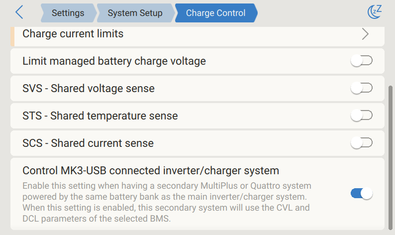 |
12.4. DVCC features for all systems
The following features apply to all system types when DVCC is enabled, regardless of whether:
The ESS Assistant is used or not
The system uses lead-acid or other standard batteries
An intelligent CAN-bus BMS battery is installed
These features are active in all configurations where DVCC is enabled.
12.4.1. Limit charge current
Limit charge current is a user-configurable setting that defines the maximum total charge current allowed in the system. It is available under: Settings → System Setup → Charge Control on the GX device. In systems with DVCC enabled, charge sources are prioritised as follows:
|  |
Particulars:
If a CAN-bus BMS is connected and the BMS requests a maximum charge current that is different from the user-configurable setting, the lower of the two will be used.
This mechanism only works for Victron inverter/chargers including Inverter RS, Multi RS, Solar chargers incl. MPPT RS and Orion XS DC-DC battery chargers. Other chargers, such as Skylla-i’s are not controlled and also their charge current is not taken into account. The same applies for devices that are not connected to the GX device, such as an alternator. Worded differently: the total charge current of the inverter/chargers and all MPPT solar chargers will be controlled, nothing else. Any other sources will be extra charge current, unaccounted for. Even when installing a BMV or other battery monitor.
DC Loads may not be accounted for, unless a SmartShunt or BMV-712 is installed and correctly configured as a DC meter. For example, without the DC load monitor a configured maximum charge current of 50A and DC Loads drawing 20A, the battery will be charged with 30A, not with the full allowed 50A. With the SmartShunt configured as a DC meter, maximum charge current configured at 50A and DC system shunt reports a draw of 25A, then the chargers are set to charge with 50 + 25 = 75A.
If you have one or more shunts configured for "DC system" (when more than one, they are added together), then the DVCC charge current limit compensates for both loads and chargers. It will add extra charge current if there is a load, and subtract it if there is another charger in the DC system. DC "loads" and "sources" are not compensated for in either direction.
Current drawn from the system by the inverter/charger is compensated for. For example, if 10A is drawn to power AC loads and the limit is set to 50A, the system will allow the MPPT solar chargers to charge with a maximum of 60A.
In all situations, the maximum charge limit configured in a device itself, i. e. the Charge current limit set with VictronConnect or VEConfigure for Orion XS DC-DC battery chargers, MPPT solar chargers or inverter/chargers will still be in effect. An example to illustrate this: in case there is only an inverter/charger in the system and in VEConfigure or VictronConnect the charge current is configured to 50A. And on the GX device, a limit of 100A is configured, then the working limit will be 50A.
DVCC charge current limits are not applied to DC MPPTs when ESS is enabled with Allow DC MPPT to export. This is to get maximum output from the solar panels for export.
12.4.2. Limit managed battery charge voltage
Some managed batteries, such as BYD and Pylontech, may require a reduced charge voltage during their initial commissioning period. This helps ensure proper cell balancing in the first few weeks of operation. The Limit managed battery charge voltage feature is designed specifically for this purpose. When enabled, it allows to temporarily reduce the maximum charge voltage, even if the battery’s BMS normally permits a higher voltage. |  |
Caution
Do not use this feature for other purposes.
Improper use may prevent cell balancing from occurring, leading to severe long-term imbalance.
If the voltage is set above the CVL (Charge Voltage Limit) from the battery BMS, the lower value will be applied.
12.4.3. Shared Voltage Sense (SVS)
This feature is compatible with VE.Bus devices, VE.Direct and VE.Can MPPT solar chargers, Orion XS DC-DC battery chargers, as well as Inverter RS and Multi RS. The system automatically selects the optimal voltage measurement. If available, it prioritises the voltage from the BMS or a BMV battery monitor. If neither is accessible, it defaults to the battery voltage reported by the VE.Bus system. The voltage displayed on the GUI corresponds to the selected voltage measurement. Shared Voltage Sense (SVS) is enabled by default when DVCC is active. It can be manually disabled via a switch in Settings → System Setup → Charge Control. However, SVS (and DVCC) is force-enabled for the Lynx Smart BMS and Lynx Smart BMS NG and cannot be modified. Note that SVS is force-disabled for some batteries. Please see the compatibility page for your battery. |  |
12.4.4. Shared Temperature Sense (STS)
STS allows the GX device to forward the measured battery temperature to all connected inverter/chargers, MPPT solar chargers, and Orion XS DC-DC chargers. You can select the temperature source from:
Note: STS is forced disabled for the Lynx Smart BMS, Lynx Smart BMS NG, and some managed batteries. Refer to the battery compatibility page for details. | |
12.4.5. Shared Current Sense (SCS)
This feature shares the battery current, as measured by a battery monitor connected to the GX device, with all MPPT solar chargers and Orion XS DC-DC battery chargers. These devices can use the shared current for the tail current mechanism, which ends absorption when the battery current drops below a set threshold. → Refer to the specific product documentation for configuration details. Applicable only to systems not using ESS and not using a managed battery, as charge control for MPPT solar chargers and Orion XS is external in those cases. Note: Requires MPPT solar charger firmware v1.47 or later. | |
12.4.6. Controlling BMS
For systems with multiple BMSs connected, this feature enables the selection of a specific BMS for DVCC. It also allows a BMV or SmartShunt to be used for SoC tracking by configuring the BMV as the battery monitor (Settings → System setup → Batteries → Battery monitor), while the BMS remains active for DVCC. This setting is available in the Settings → System Setup → Charge Control menu on the GX device. |   |
12.5. DVCC features when using CAN-bus BMS battery
This section applies to all systems using an intelligent battery BMS connected via CAN-bus.
This excludes the Victron VE.Bus BMS.
Such intelligent BMS sends the following parameters to the GX device:
For all three parameters, some types of batteries transmit dynamic values. For example they determine the maximum charge voltage based on cell voltages, state of charge, or for example temperature. Other makes and brands use a fixed value. For such batteries there is no need to wire allow to charge (ATC) and allow to discharge (ATD) connections to the AUX inputs of a Multi or Quattro. |  |
When inverting (i.e., in island mode), Multis and Quattros will shut down if the maximum discharge current is set to zero. They will automatically restart when either AC mains is restored or the BMS increases the maximum discharge current.
For more information on how the maximum charge current is configured, including prioritization of solar, refer to the previous section, Limit charge current.
Notice
It is important to note that configuring charge voltages or charge profiles in VEConfigure or VictronConnect is unnecessary and has no effect. The Multis, Quattros, Multi and Inverter RS, MPPT Solar Chargers, and Orion XS DC-DC battery chargers will charge using the voltage received via CAN-bus from the battery. This setup also applies to systems with a Lynx Smart BMS or Lynx Smart BMS NG connected to a GX device.
12.6. DVCC for systems with the ESS Assistant
 |  |
The ESS Keep batteries charged mode will only work properly with DVCC enabled.
A fixed solar offset of 0.4V (value for 48V system, divide by 4 for 12V) is applied when ESS-mode is set to Optimised in combination with the Feed-in excess solar charger power-setting enabled, or when ESS-mode is set to Keep batteries charged.
For system with ESS mode Optimised and Optimised (with BatteryLife): The system will automatically recharge the battery (from the grid) when the SoC drops 5% or more below the value of ‘Minimum SoC’ in the ESS menu. Recharge stops when it reaches the Minimum SoC.
ESS status display in the graphic overview of the GX device and on VRM: In addition to the charge status (External Control or Bulk/Absorption/Float), the following status can be displayed:
ESS status
Meaning
#1
Low SoC: discharge disabled
#2
BatteryLife is active
#3
Charging disabled by BMS
#4
Discharging disabled by BMS
#5
Slow charge in progress (part of BatteryLife, see above)
#6
User configured a charge limit of zero
#7
User configured a discharge limit of zero
Note: When DC-coupled PV feed-in excess is enabled with ESS, the DVCC system will not apply the DVCC charge current limit from PV to battery. This behaviour is necessary to allow the export. Charge voltage limits will still apply.
Charge current limits set at the individual solar charger device settings level will also still apply.
When the BMS is disconnected in an ESS system, solar chargers will stop and show error #67 – No BMS (see the MPPT Solar Charger Error Codes for additional info).