Just over a year ago there was a blog about Hydro Power, in which Markus Pauritsch used a Victron MPPT solar charge controller loaded and driven by a Pelton wheel water turbine to charge his off-grid cabin battery system in the Austrian Alps.
As you may also recall a few weeks ago we left the subsequent blog: DIY ingenuity: Hydro Power MkII – Part I at the point where the rebuilt system (after a storm) and his neighbour Werner’s brand new (joint venture) system were at the testing stage. But how did that go, did it all work?
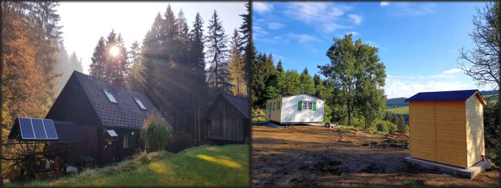
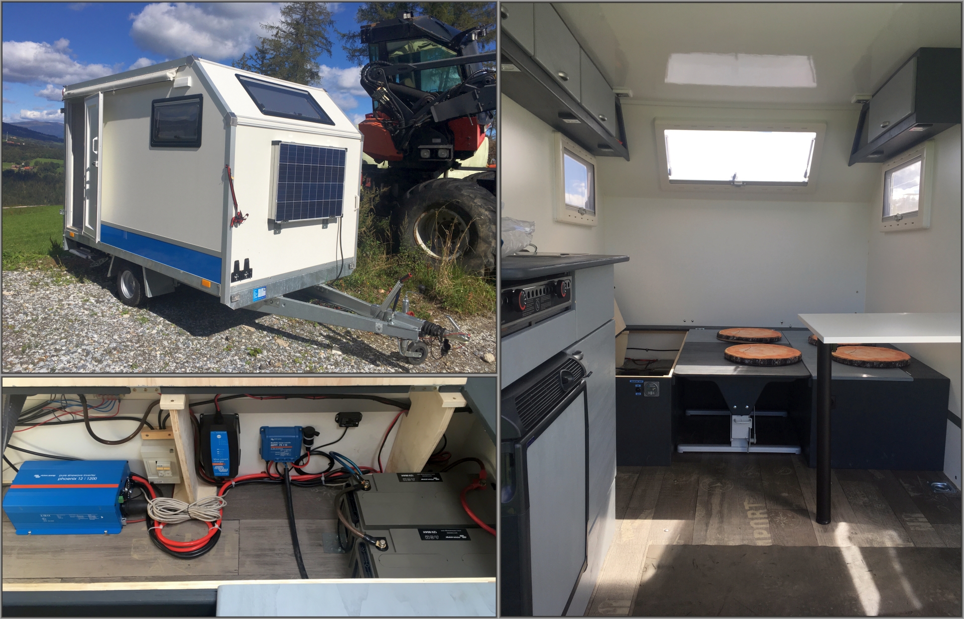
Just before we get into that – Markus’s off-grid cabin and Werner’s nearby new off-grid static mobile home with its power system shed are shown above. Not only do both systems use Victron Energy products but I also discovered Werner has gone ‘Victron Everywhere’, equipping his micro off-grid trailer too!
Hydro Testing
Here’s what Markus & Werner had to say about this phase of the project:
“The first pressure tests turned out to be not so successful. The pressure went up to 7 Bar, but we had to make several attempts to keep the hose stable and tight. We connected the hose from the supply-pond with a pipe consisting of segments and we used ‘special’ foam to stick them together.
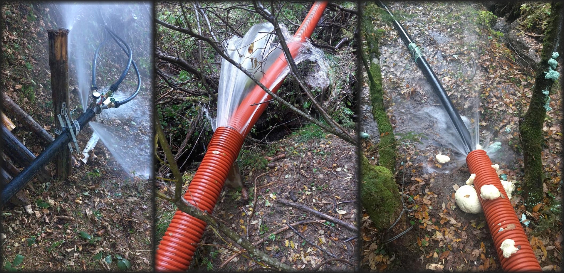
Lessons were learned. Don’t use foam for that! Not only because it doesn’t last, but it can get into the main hose and getting it out was difficult to say the least. Plan B and we used a reduction and connected the segments with clamps. After everything was tight we had a stable pressure of 8 Bar.
Voltage measurements at the hydro generators brought up very much higher open circuit voltages, than expected from the seller’s datasheets, measuring 160V after rectification from the smaller generator and 307V from the larger one. That was too much for both of our chargers as the maximum input voltage is 150V for mine and 250V for Werner’s.
So I came to the conclusion to build an electric brake system. Tests with some 100 Watt light bulbs connected in parallel revealed that I need 1A of load current for the smaller generator and 1.375A for the bigger one to bring it down to a safe voltage.”
Electrical braking
After thinking about potential solutions Markus came up with 3 possibilities.
- Connect a power resistor in parallel to the rectified generator output to brake it. This would be the easiest way, but usable energy would be lost through the resistor, something Markus didn’t like.
- Build a voltage stabilisation circuit with a transistor, a power resistor and a Z-diode that would short circuit the generator at e.g. 230 plus volts to brake the system. The problem was, that they would be need to be active circuits which are complicated to calculate and build. The worst part is, they would tend to oscillate.
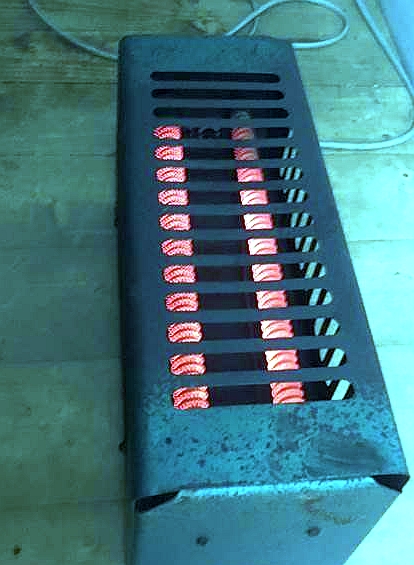
- Build a serial diode brake. The idea here was, that a silicon diode is not fully conductive in transmission direction below 0.7V.
Solution 3 became the initial choice. 300 were soldered in series and then connected in parallel to the rectified generator output. The diode characteristics would then be the generators ‘brake characteristics’.
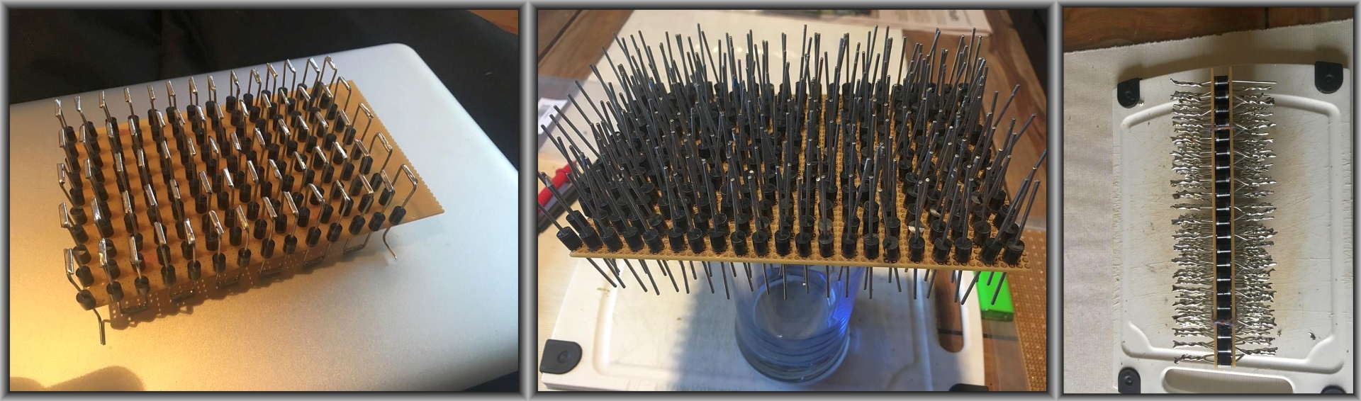
The cost of 300 pcs. 5A diodes was about 30 Euros. Markus thought they would work, as he needed ‘only’ around 1A of load current to brake the generators and bring them down to the required voltage. It seems though, that he under estimated what it means to burn up to 300Watts of energy. The diode bridges worked, but got hotter than anticipated. A new approach was needed.
Markus calculated some power resistors (solution 1) and all looked good on paper and worked in practice. For the smaller Pelton wheel, the resistor brake works perfectly braking to 132V, a safe input voltage for his MPPT charger.
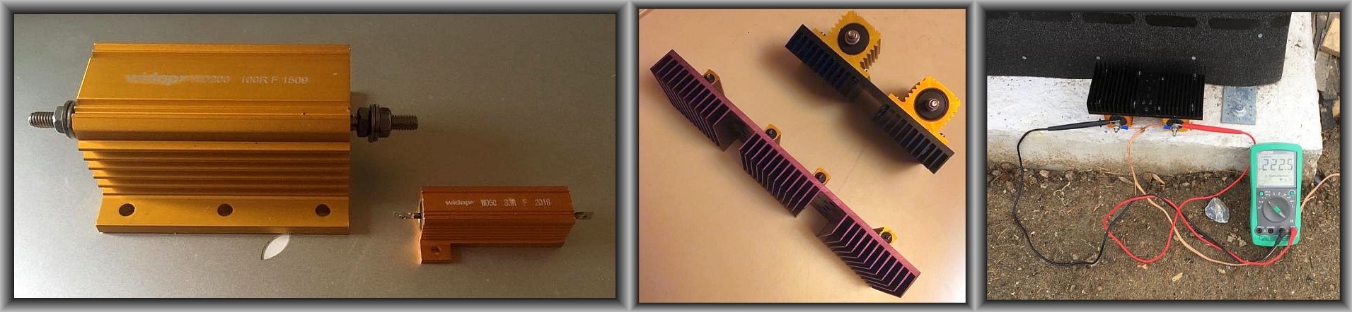
For the larger Pelton wheel he got a voltage of 222.5 Volts.
The MPPTs were then connected to the rectifiers and a generator maximum power output test was conducted. The larger Pelton wheel had too small a nozzle setting and so it did not reach sufficient RPM under higher loads. The solution was to drill the nozzles, altering them from 6mm to 8mm. As a result, the generator now went to high speed under load, producing 270V with the power resistor brake and 330V without. As the larger MPPT is rated at 250V, it was disconnected before any damage was done. More lessons were learned – first do the nozzle setup, then calculate and buy the brake resistors.
Werner’s brake resistor was subsequently removed and a heater used as a brake, which works perfectly keeping his larger MPPT within the correct voltage range.
Power Test Results
The results turned out really well.
Smaller generator
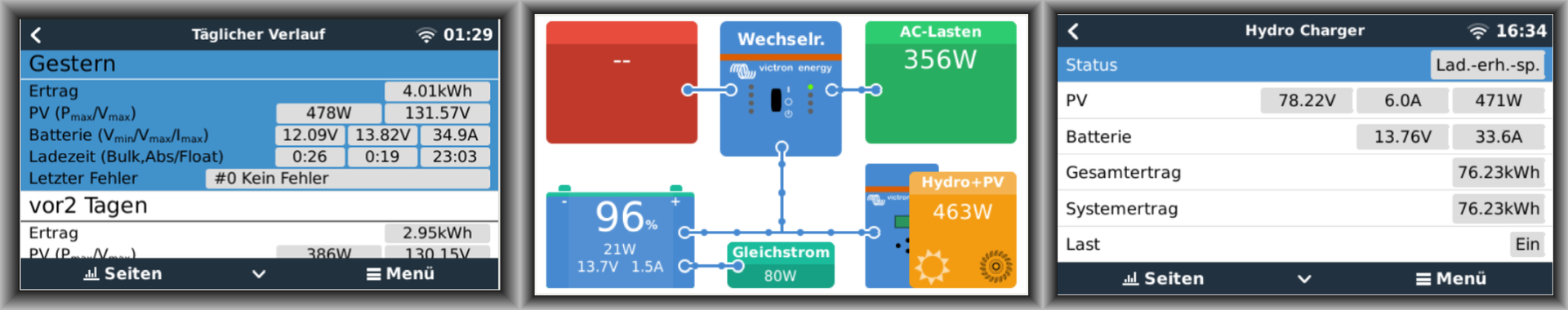
Click to enlarge – note the Pelton wheel on the Venus screen of the Raspberry Pi. Tricky to do but Markus did it.
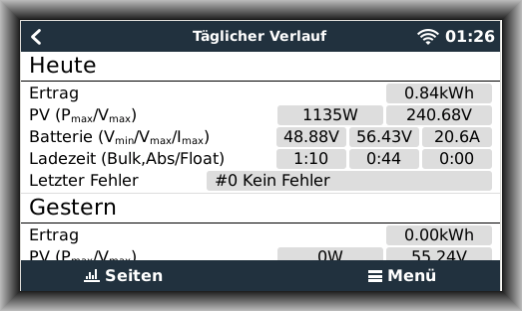
Larger generator
Werner’s completed Energy Hut.
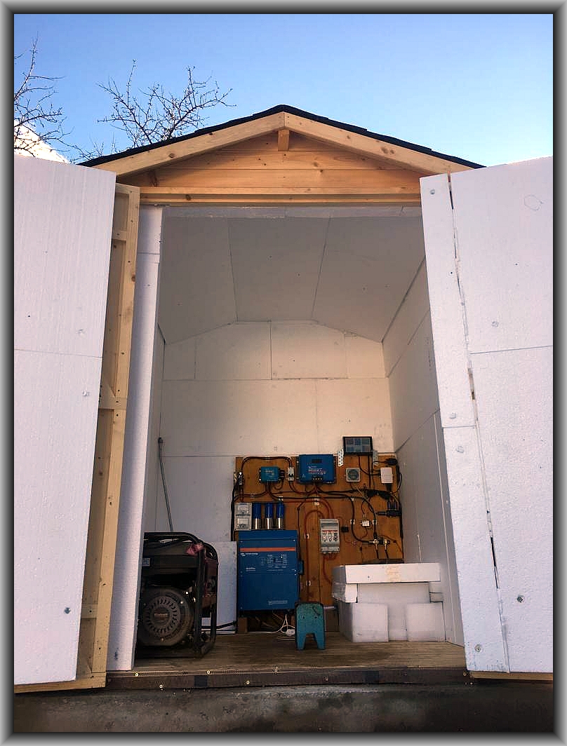
Werner’s completed Energy Hut. Note he and Markus use a MultiPlus each as they both have a 2.5KVA gasoline generator each for backup, connected to AC in on the Multi.
Conclusion
Markus tells me:
“Implementing Hydro Power was a major step forward to having continuous renewable off-grid power. In the winter the solar yield is poor because of the sun angle and as there is no possibility for us to connect to the grid, hydro was the only option. We are very pleased with the updated system and if we carry out any further improvements I’ll keep you updated.”
John Rushworth
Credits
Markus Pauritsch for the information and images used in this blog.
Markus would like to thank all the willing helpers, his Victron Energy dealer Polz Solar and in particular Peter Polz himself, who Markus tells me has given outstanding support – even when using MPPT solar charge controllers as Hydro Power charge controllers!
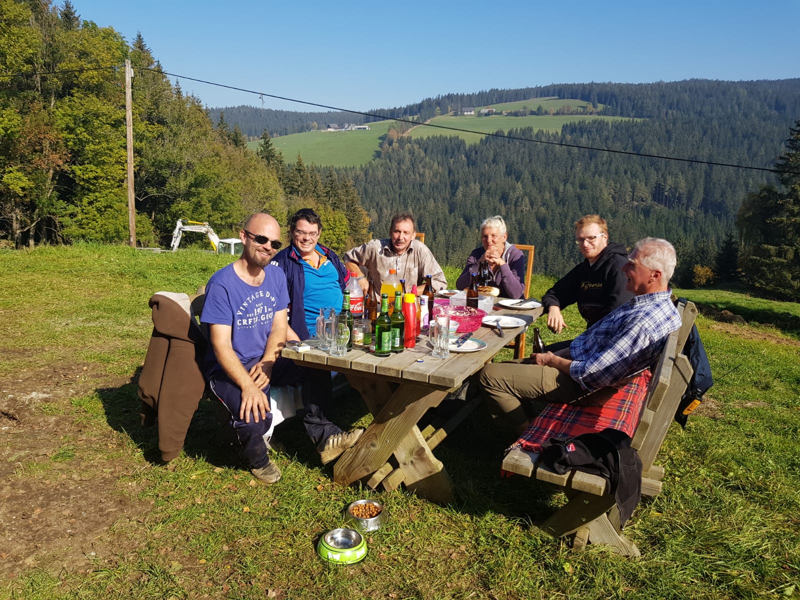
The Hydro project team.


