Life used to be so simple; in a 12V battery system you took a ‘12V’ solar module, watched carefully that the maximum PV current would not exceed the charge controller maximum current and the system would work.
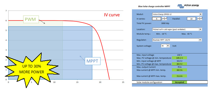
Unfortunately due to the fact, that with PWM controllers the PV module is not feeding the battery from its maximum power point (MPP), the system loses a lot of energy. In the following diagram you can see, the area of the MPP in blue (Vmpp * Impp) is up to 30% larger than the PWM area (Vbatt * ~Isc) within the IV curve. 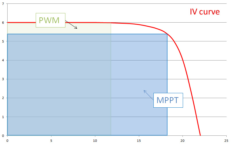 So, with the advent of the newer Victron Energy Blue Solar MPPTs, things changed for the better when compared to PWM solar charge controllers.
- If a specific yield is the goal, the 30% higher efficiency of the MPPT will reduce system costs, because the same energy can now be produced with a smaller PV generator.
- If the size of the solar module was already fixed, the yield is now higher in the same system when using an MPPT.
In both cases the user is a winner!
Sizing the system can be done electrically to see if the system is allowed and will not destroy any components, when looking at the yield to see how much energy it will produce. For now I will look at the first part, to find out what is possible on the electrical side.
By adding a DC/DC converter in the Blue Solar MPPT controller, the system also becomes more flexible when we look at the input voltage of the controller. The challenge now, is to match the PV modules to the controller, because we are not concentrating on only ‘12V’ or ‘24V’ modules anymore. Basically any module can now be used if it is within the input voltage range of the charge controller.
In fact we can now put modules in series as well as parallel, which will also increase the input power and flexibility. Thanks to the output power or current limiter, the output power will never exceed the maximum of the controller. This Blue Solar MPPT feature is unique and makes the charge controller even more interesting!
You can now for example add the same type of modules in parallel later without the need to change the MPPT charge controller. This reduces costs to a minimum, whilst still increasing the yield!
Also, I took the values for all our Blue Solar MPPT charge controllers and Blue Solar modules and combined them into a Spreadsheet. Now sizing a Blue Solar MPPT charge controller is easy!
Download: VE-MPPT-Calc.xlsx (744KB) – This configuration spreadsheet is compatible with MS Excel.
Now for the technical explanation, for those who would like to know some more details:
Exceeding the input voltage range will (as it did with the PWM controllers) damage the controller permanently.
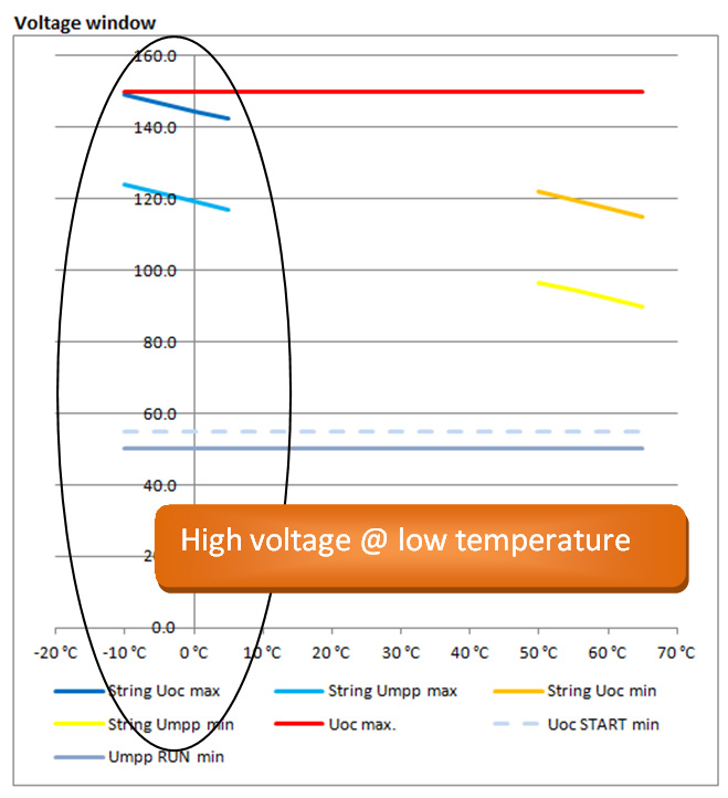
Of course we will also need to take a look at the minimum voltage, where the Blue Solar MPPT controller will start working. If you take a SPM50-12, the Open Circuit Voltage (Voc) is 22.2V and the maximum power voltage (Vmpp) is 18V at Standard Test Conditions (STC) which means 1.000W/m² irradiation, 25°C cell temperature and an Airmass of 1.5. If the cell temperature is higher or less than 25°C, this voltage reduces or increases due to the temperature coefficient, in this case -0.34%/°C (see Blue Solar module datasheet).
So if you take 3 modules SPM50-12 on a Blue Solar MPPT 150/70 in a 48V system on cold days say, -10°C (only looking at the voltage), you can start up charging:
The startup voltage is 48V + 7V (see MPPT 150/70 datasheet) = 55V The modules will produce 3 * ( 22.2V + (-0.34% of 22.2V * -35°C temperature difference)) = 74.5V 74.5V is higher than 55V -> that’s perfect
Also running in the MPP the system would work:
The running voltage is 48V + 2V (see MPPT 150/70 datasheet) = 50V The modules will produce 3 * ( 18V + (-0.34% of 22.2V * -35°C temperature difference)) = 61.9V 61.9V is higher than 50V -> that’s perfect
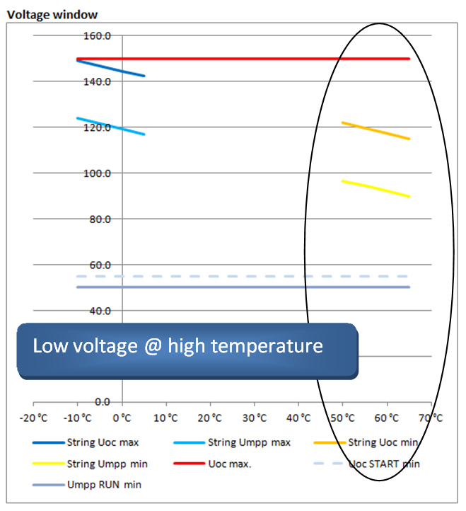
Doing the same thing, when the modules get warm during the day, in this case 70°C you can see what happens:
The startup voltage is still 48V + 7V (see MPPT 150/70 datasheet) = 55V The modules will produce 3 * ( 22.2V + (-0.34% of 22.2V * 45°C temperature difference)) = 56.4V 56.4V is higher than 55V -> that would work
But now in the MPP the module voltage is lower than the minimum:
The running voltage is 48V + 2V (see MPPT 150/70 datasheet) = 50V The modules will produce 3 * ( 18V + (-0.34% of 22.2V * 45°C temperature difference)) = 43.8V 43.8V is lower than 50V -> this is not enough!
The high DC/DC conversion efficiency (97.5% at 48V) will result in following output maximum charging current (@ -10°C) of 61.9V Vmpp* 2.74A Impp / 48V Battery voltage * 0.975 Efficiency = 3.45A This is far below the maximum of 70A, so it will be all used to charge the battery.
Increasing the number of modules per string to 6 in series and making 10 strings in parallel gives the following result at -10°C:
The Voc will remain under the maximum of 150V at -10°C
Now at high temperatures such as a 70°C cell temperature the system will work just fine! Taking this example in the Spreadsheet you can now increase the number of strings in parallel and you will see, if starting at 11 strings, that the controller will start to reduce power. The big advantage in doing this is that you will now produce the maximum controller output at a lower irradiation. As module prices decrease, this is an effective option.
Please note, that you can use ‘preconfigured’ minimum and maximum temperatures. I’ve also given some installation examples, at the bottom of the spreadsheet, with their anticipated module temperatures for various types of installations.
Oversizing a PV array
Oversizing a PV array means installing more peak power (Wp) than the maximum charge power of the chosen MPPT charge controller. A common reason to oversize is to cater for winter time when the sun is not as powerful.
The MPPT solar sizing calculator will allow for a 130% PV array oversizing when recommending a charge controller.
The design logic is that panels RARELY spend much time at their peak rated output capacity, only maybe an hour in the middle of a sunny day. The rest of the time they are derated below their spec maximum, and less than the maximum capacity of the charge controller.
Some installers don’t like to do this however, and will override it so that the panel output is never constrained. The best choice will depend on the installation, and may take into account a limited roof area, or limited solar window (due to shading).
Another reason to oversize panel to charge controller capacity is that PV panel output degrades over time, as they get soiled, dirty, PID, etc.
Generally total energy harvested from a 130% panel oversizing results in less than 1% annual energy loss.
Limits to Oversizing a PV array
How to determine by how much you can oversize a PV array? This can be done with help from the spreadsheet tool. Here though is the manual explanation of how it is done.
There are two limits, when determining the maximum array size that can be connected to an MPPT:
-
The Maximum PV open circuit voltage (Voc at STC)
-
The Maximum PV short circuit current (Isc at STC)
Both values are specified in the datasheets of all our MPPT Solar Charge Controllers. Those two ratings of the PV array must not exceed these MPPT limits.
Note that these two maximum ratings must not be multiplied to determine the maximum installable peak power. Instead, each of them needs to checked by itself:
Determining the maximum PV open circuit voltage
First look at the datasheets of the solar panels to see what their maximum open circuit voltage is. Then multiply that by the number of panels that are in series in the array. The result of the multiplication must not be higher than the Maximum PV open circuit voltage as listed on the MPPT Datasheet. Make sure to take into account the coldest expected temperature. The colder it is, the higher the open circuit voltage on a PV array will be.
Determining the maximum PV short circuit current
Get the maximum PV short circuit current from the PV Panel datasheet. Multiply by the number of panels in parallel in the array. Having more panels in series does not change the number.
The result of the calculation may not exceed the Max PV short circuit current as specified in the MPPT Datasheet.
Good luck and enjoy sizing the BlueSolar MPPT Charge Controller!
Kind regards,
Bob Hopman – Victron Energy


