4. Operation, configuration and monitoring
4.1. Automatic engine shutdown detection
The automatic engine shutdown detection simplifies the Orion XS system by detecting whether the engine is running, without wiring additional switches or sensors. The factory default setting will work with most conventional and smart alternators but can be re-configured with the VictronConnect App.
The detection is based on the alternator voltage. Conventional alternators will generate a fixed voltage (e.g. 14V), whereas the voltage of smart alternators can vary between 12.5V to 15V (for a 12V system). Smart alternators in a regenerative braking system often show large voltage variations.
Engine shutdown detection is only active in charger mode. The feature can be configured, disabled and reactivated as described in the Engine shutdown detection & input voltage lock-out section. In power supply mode, the Input voltage lock-out determines when the output is active.
In installations where the alternator voltage does not give the detection enough to work with, an external engine running signal can be used instead; see the Using an external engine running signal section.
4.1.1. How it works
The following procedure describes the operation of the engine shutdown detection sequence.
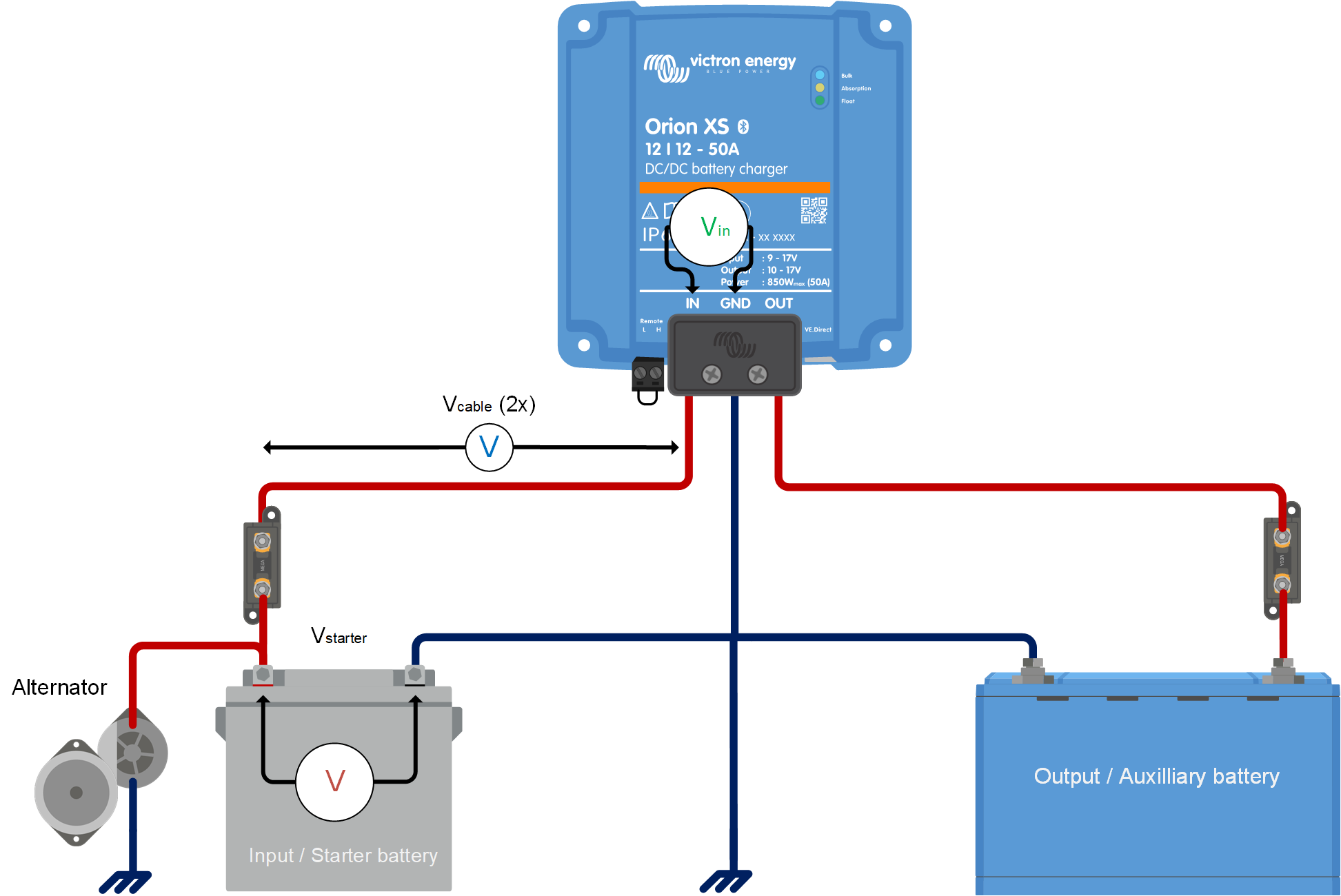 | 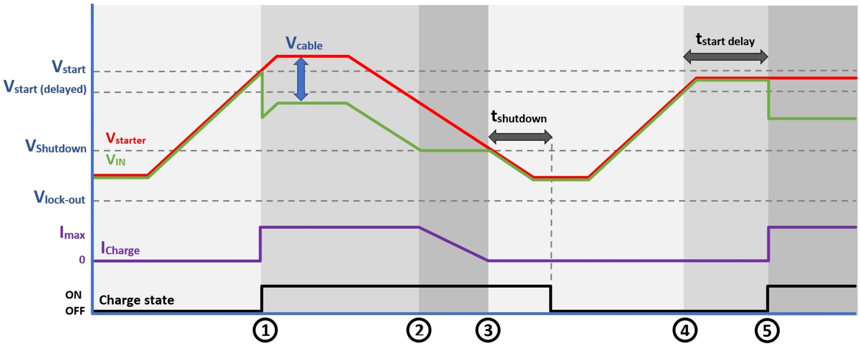 |
Engine shutdown detection sequence
0 → 1: If the engine runs, the alternator voltage will ramp up. When Vstarter > Vstart, charging is enabled.
1 → 2: The input current produces a voltage across the input cable (Vcable); this voltage reduces the voltage measured by the charger (VIN). If VIN > Vshutdown, the charger will operate at Imax.
2 → 3: If VIN ≤ Vshutdown, the charge current will be reduced to prevent VIN to drop below Vshutdown.
3 → 4: If VIN < Vshutdown for longer than 1min (tshutdown), “engine off” is detected and charging is disabled. If VIN > Vshutdown before tshutdown runs out, charging remains enabled.
4 → 5: If Vstart(delay) < VIN < Vstart, charging is enabled after tstart delay (configurable).
4.1.2. Setup for Euro 6 vehicles
Euro 6 vehicles use a smart alternator that is managed by the vehicle. While driving, the alternator management system decides whether the alternator is needed, based on the electrical demand of the vehicle and on how much energy can be recovered during braking. As a result, the charge voltage is not constant: it can vary roughly between 12.5V and 15V in a 12V system, and the alternator can be switched off completely for a while. When the alternator is switched off, the voltage at the starter battery falls back to the static battery voltage (~12.6 V). The engine shutdown detection reads that voltage and can conclude that the engine has stopped, even though the vehicle is still driving. During this phase, the Orion XS will not charge, potentially resulting in an undercharged auxiliary battery.
The alternator management system also reacts to the electrical demand in the vehicle. When enough loads are present, the alternator produces at least a float-level voltage (~13.8V), which the engine shutdown detection recognises without difficulty. If the base load in the system is sufficiently high, the alternator remains active for most of the drive and the automatic detection works well.
Whether this happens depends on the vehicle and on the installation, so the engine shutdown detection sometimes needs fine-tuning. Four settings are available for this in the VictronConnect App: the start voltage, the delayed start voltage, the delayed start voltage delay and the shutdown voltage. See the Engine shutdown detection & input voltage lock-out section for a description of each setting. Lowering the start and shutdown voltages makes the detection tolerate the lower charge voltages of a smart alternator, at the cost of a smaller margin above the static battery voltage.
Be aware that charging strategies differ from vehicle to vehicle, even within the same brand and model. Owners of the same vehicle model may find that some can successfully utilise engine shutdown detection, while others experience undercharged auxiliary batteries.
In a vehicle where the alternator is switched off for long periods and the base load is low, fine-tuning may not be enough to keep charging going. An external engine running signal can be used instead; see the Using an external engine running signal section.
4.1.3. Using an external engine running signal
The engine shutdown detection determines whether the engine is running from the input voltage. In some vehicles the alternator voltage does not follow the engine, for example when a smart alternator is switched off for long periods while driving. In such an installation, a signal from the vehicle can be used to tell the Orion XS that the engine is running.
Such a signal is connected to the remote L-pin. While the signal is present, it overrides the engine shutdown detection and charging is forced on. While the signal is absent, the Orion XS returns to the engine shutdown detection, which decides whether the engine has stopped. For the wiring, see the External engine running signal wiring section.
Note
Leave the engine shutdown detection enabled in the VictronConnect App when an external engine running signal is used. The signal only forces charging on; stopping charging when the engine is off remains the task of the engine shutdown detection.
Warning
When the engine shutdown detection has been switched off in the VictronConnect App ('forced charging'), current will be drawn from the starter battery even if the engine is not running, regardless of any external signal that is connected. The input voltage lockout is then the only limit left to disable charging automatically; make sure this level is not set too low, in most applications 12.5V is sufficiently low.
Which signal to use
Several sources can provide an external signal. Each has its drawbacks, which should be understood before choosing one.
Vehicle engine running signal:
This is the most accurate source, as the signal comes from the vehicle's own system and follows the engine directly. However, accessing this signal can be challenging, and it may require activating the function in the vehicle's software.
Pulled-low engine running signal:
Some vehicles provide an engine running signal that is pulled to ground (battery minus) while the engine is running. This is the opposite of what the L-pin expects, so the signal cannot be connected to the L-pin directly. A relay is used to convert it; see the External engine running signal wiring section.
D+:
The D+ signal, which comes from the alternator, indicates that the alternator is active. In Euro 6 vehicles this signal is often no longer provided, making it unusable. There are D+ simulator devices that generate a signal based on the alternator voltage, but these work from the same voltage that the engine shutdown detection already measures, so in an installation where the alternator voltage is the problem they offer no advantage.
Ignition switch:
It is common to use the ignition switch to enable charging. While this method is not inherently wrong, it allows the Orion XS to discharge the starter battery when the ignition is on but the engine is not running. This requires the user to be vigilant about when charging is permitted, to avoid a flat starter battery. Therefore, we do not recommend using the ignition switch to enable charging.
Vibration sensor:
This device generates a voltage when it detects engine vibrations. Be aware that external vibrations, such as those from transport on a boat or train, or even loud music, can be mistaken for a running engine. To mitigate this, power the vibration sensor from an ignition-switched source, so that charging is only permitted when both the ignition is on and vibrations are detected.
CAN bus interface with engine running output:
This device reads the engine running command broadcast on the CAN bus and converts it into an on/off signal. This requires tapping into the CAN bus, and the ease of access varies between vehicles.
4.2. Emergency reverse charge
The emergency reverse charge function charges a depleted starter battery from the auxiliary battery, so that the engine can be started again. It is intended for situations where the starter battery no longer holds enough energy to crank the engine, for example after the vehicle has been parked for a long time or when the starter battery has been drained by a load.
During an emergency reverse charge, the Orion XS temporarily reverses its normal charge direction: energy flows from the auxiliary battery connected to the output to the starter battery connected to the input. In the VictronConnect App, this reversed flow is shown as negative input and output current values.
Note
Emergency reverse charge function requires Orion XS firmware v1.15 and VictronConnect v6.43 or later.
For the procedure, see Starting an emergency reverse charge.
Start conditions
The emergency reverse charge button on the Status screen of the VictronConnect App is always present, but it is only active while an emergency reverse charge is possible.
An emergency reverse charge is only possible when the Orion XS is in charger mode and the charger is off for one or both of the following reasons:
The input voltage lock-out is active.
The engine shutdown detection has determined that the engine is not running.
A remote off does not block an emergency reverse charge. The function stays available when the Orion XS is switched off via remote on/off.
The emergency reverse charge sequence
An emergency reverse charge runs for a fixed time and consists of two phases:
| 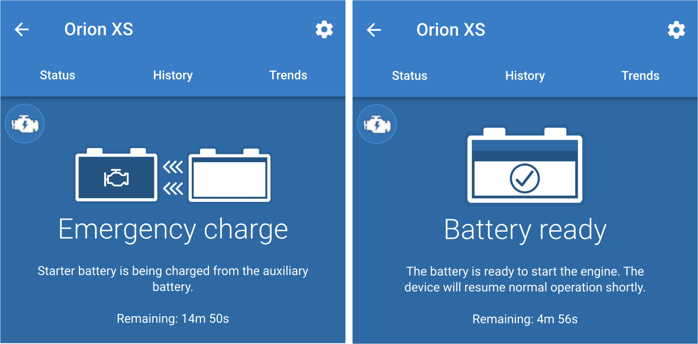 |
After the settling period has ended, the Orion XS resumes normal operation.
Note
The engine can be started as soon as the app shows Battery ready.
Important
Battery ready indicates that the 15-minute emergency reverse charge has finished. It does not guarantee that the starter battery is able to crank the engine. An emergency reverse charge transfers a limited amount of energy to the starter battery; it cannot restore a starter battery that is defective or at the end of its service life.
Reverse charge current
The reverse charge current is half the rated charge current of the device. If a lower input or output current limit is configured for normal charging, the lowest configured limit is used instead. The app states the limit that will be applied before the emergency reverse charge is started.
The starter battery is charged to a maximum of 14,4 V.
To protect the auxiliary battery against deep discharge, the Orion XS maintains the auxiliary battery voltage at 12 V. As the auxiliary battery approaches this level, the reverse charge current is reduced, so that as much energy as possible is transferred without deeply discharging the auxiliary battery.
If the auxiliary battery is already at or below this level when the emergency reverse charge starts, the function still runs but no current is transferred. Current only begins to flow if the auxiliary battery voltage rises above the level again during the charge, for example because another charging source is charging the auxiliary battery.
Note
Minimise the load on the auxiliary battery from other connected devices during an emergency reverse charge.
The requested reverse charge current is not always reached. See The reverse charge current is low or zero for the possible causes.
Monitoring and settings
The state, the input and output voltages and the input and output currents can be followed in the VictronConnect App. It is not necessary to stay connected to the Orion XS while the sequence runs.
The settings cannot be changed while an emergency reverse charge is in progress, including during the settling period. The Settings page of the VictronConnect App shows a message stating that the settings will be available again once the emergency reverse charge has finished.
4.2.1. Starting an emergency reverse charge
An emergency reverse charge is started from the VictronConnect App. The Orion XS must be set to charger mode; the emergency reverse charge button is greyed out in power supply mode.
For a description of the function and the conditions under which an emergency reverse charge can take place, see Emergency reverse charge.
Caution
In systems with more than one Orion XS connected in parallel, either start an emergency reverse charge on all of them or switch the others off first.
A Orion XS that is reverse charging raises the starter battery voltage. Another Orion XS that is still in normal operation reads that rise as a running engine and starts charging forward, so the two units charge against each other.
The result is a circulating current between the units. Energy is drawn from the auxiliary battery without reaching the starter battery, and the engine may still not start.
| 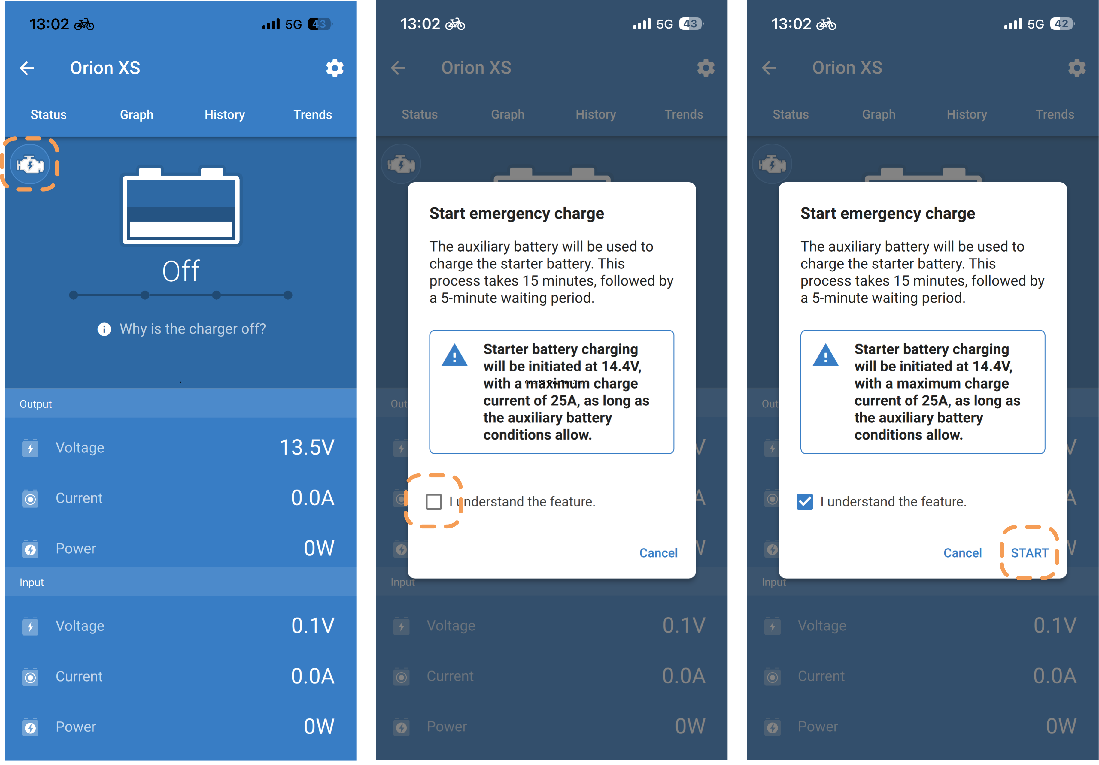 |
Stopping an emergency reverse charge
An emergency reverse charge can be stopped before it has finished. Tap the engine icon again and confirm with STOP in the window that opens. NoteThe settling period does not run in this case: the Orion XS returns to normal operation directly. | 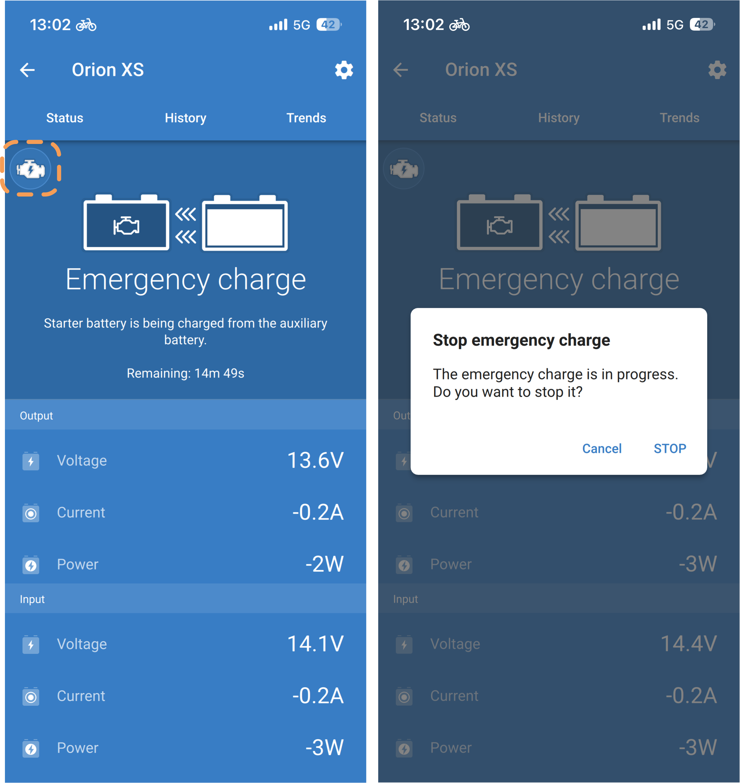 |
4.3. LED indicators
The Orion XS has 3 coloured LEDs showing the charger's status. Their meaning and behaviour are explained below.
LED status:
LED behaviour | Description | Symbol |
|---|---|---|
On | Permanently on |  |
Off | Permanently off |  |
Very slow blinking | Blinking 1x per 1.6s |  |
Slow blinking | Blinking 2x per 1.6s |  |
Blinking | Blinking 4x per 1.6s |  |
Fast blinking | Blinking 8x per 1.6s |  |
Pulsating | Short pulses per 1.6s |  |
LED indications overview:
Orion XS status | Bulk LED | Absorption LED | Float LED |
|---|---|---|---|
Off |  |  |  |
Error mode |  |  |  |
Identify |  |  |  |
Power supply mode |  |  | |
Emergency reverse charge |  |  | |
Battery ready | | | |
Bulk mode | | | |
Absorption mode | | | |
Float mode | | |  |
Storage mode | | |  |
Equalisation mode | | |  |
Repeated absorption mode | | | |
BatterySafe | | | |
Software update | | | |
Other | | | |
4.4. Setup & monitoring with VictronConnect
This chapter will help you get the most out of your Orion XS using the VictronConnect App and requires minimal knowledge of this battery charger.
For more general information on the VictonConnect App, how to install it, how to pair it with your device and how to update the firmware, see the VictronConnect manual.
4.4.1. Setup
VictronConnect allows to change or adjust various settings of the Orion XS. This is possible through the settings option, which can be accessed by clicking on the cog wheel icon in the top right corner of the screen. The setting options vary depending on the selected operating mode.
4.4.2. Charger mode settings
When in Charger Mode, these are the available settings: | 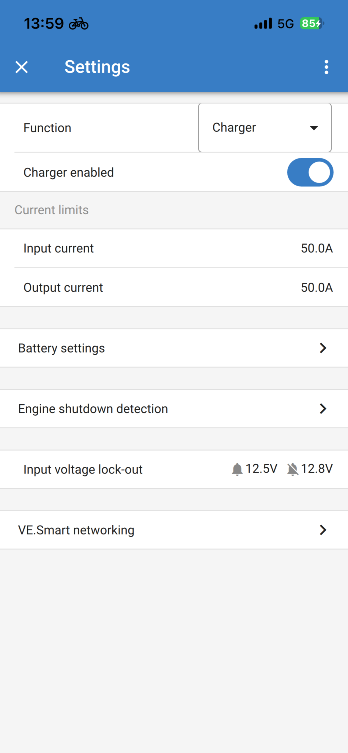 |
Function: Allows for the choice between “Charger” or “Power supply” mode. When Charger mode is selected, the Orion XS will follow the charge algorithm. For more information about the charge algorithm, please read the Features section. | |
Charger enabled/disabled: The charger is enabled by default. Use the switch to disable the charger if necessary. | |
Input current: Limits the maximum current drawn from the input source. This is particularly important to avoid overloading an alternator or other weak input sources. The value can be adjusted between 1 A and 50 A in 0,1 A increments. | |
Output current: Limits the maximum output current. The value can be adjusted between 1 A and 50 A in 0,1 A increments. | |
Battery settings: Allows to change the battery settings in order to adjust the absorption voltage, float voltage, and others to fit the battery being charged; see the Charger mode - Battery settings section for details. | |
Engine shutdown detection: Allows three voltage limits and a delay time to be selected. One voltage limit is used to determine whether the engine has stopped, and two are used to detect whether the engine is running (again). Normally, a minimum difference of 0,2 V is used for optimal operation. If desired, the protection can still be disabled by the user. For more information, please read the Automatic engine shutdown detection and Engine shutdown detection & input voltage lock-out sections. | |
Input voltage lock-out: Allows to choose between two thresholds, one to set the lock-out value and another for the restart value. Normally, a minimum difference of 0.5 V is recommended for proper operation. The protection can still be disabled if desired by the user. For more information about the input voltage lock-out, please read the Automatic engine shutdown detection section. |
4.4.3. Charger mode - Battery settings
| 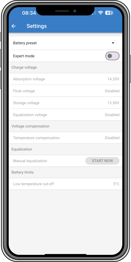 |
4.4.4. Power supply mode
Orion XS [serial number] or a specified custom name confirms the connected device. | 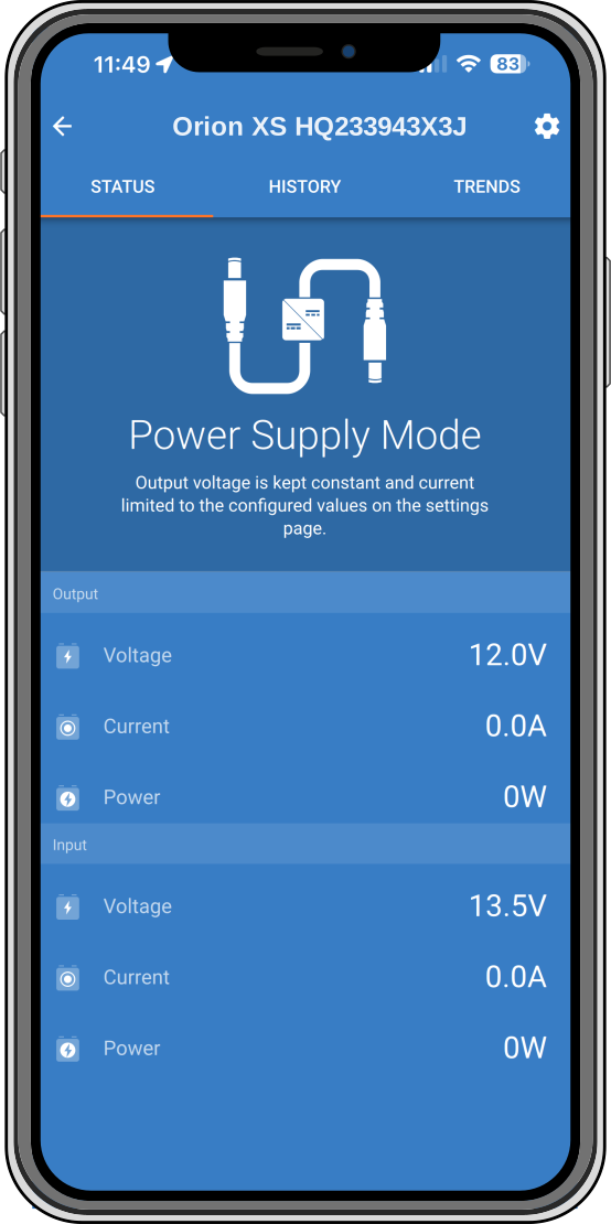 | |
Mode icon: indicates which mode the Orion XS is operating in (in this case Power Supply Mode). | ||
Output voltage: Voltage measured at the output terminals of the device. | ||
Output current: Output amperage. | ||
Output power: Output power in Watts. | ||
Input voltage: Voltage measured at the input terminals of the device. | ||
Input current: Current drawn by the charger. | ||
Input power: Input power in Watts. | ||
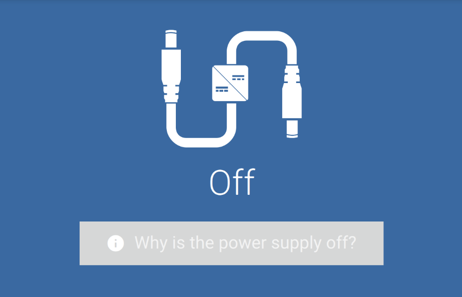
Why is the power supply off?: Appears instead of the Power Supply Mode text and displays the reason why the Orion XS is turned off. |
|
4.4.5. Power supply mode settings
Function: Allows you to choose between Charger and Power Supply Mode. When the Power Supply Mode is selected, the Orion XS keeps the output voltage stable as specified in the setting. | 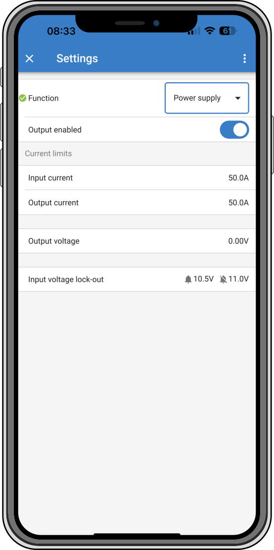 |
Output enabled/disabled: Output is enabled by default. Use the switch to disable the output if necessary. | |
Input current: Limits the maximum current drawn from the input source. | |
Output current: Limits the maximum output current. | |
Output voltage: Allows to choose the output voltage when Power Supply Mode is selected. Note that the minimum and maximum voltages needs to be within the product limit (i.e.: 10V to 17V for a 12V output Orion XS). | |
Input voltage lock-out: Allows to choose between two thresholds. One to set the shutdown level and another for the restart value. Normally, a minimum difference of 0.5V is recommended for proper operation. |
4.4.6. Engine shutdown detection & input voltage lock-out
Engine shutdown detection
To configure engine shutdown detection settings, open VictronConnect, connect to your Orion XS and from the status page press the cog icon to get to the Settings page.
The following settings can be changed with VictronConnect:
Engine shutdown detection enabled/disabled: The engine shutdown detection is always enabled by default whenever the charger mode is selected. When the function is disabled or when power supply mode is selected, the engine is considered to be running, so no shutdown detection will take place. Leave the engine shutdown detection enabled when an external engine running signal is connected: the signal only forces charging on, and disabling the detection makes the charger charge continuously regardless of the signal. See Using an external engine running signal. |  | |
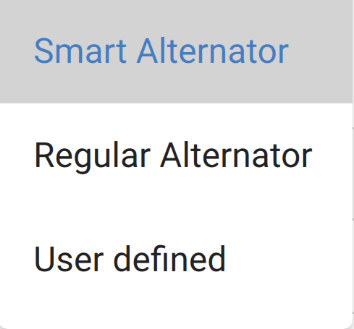
Alternator type: For the type of alternator you can choose between “Smart alternator”, “Regular alternator” and “User defined”. When the "Smart alternator" option is selected, the default values for the smart alternator will be applied to the engine shutdown detection settings. The same will happen when "Regular alternator" option is selected. When any of the settings differs from the default values of the last two option, the "User defined" option will be selected. Default: smart alternator. |
| |
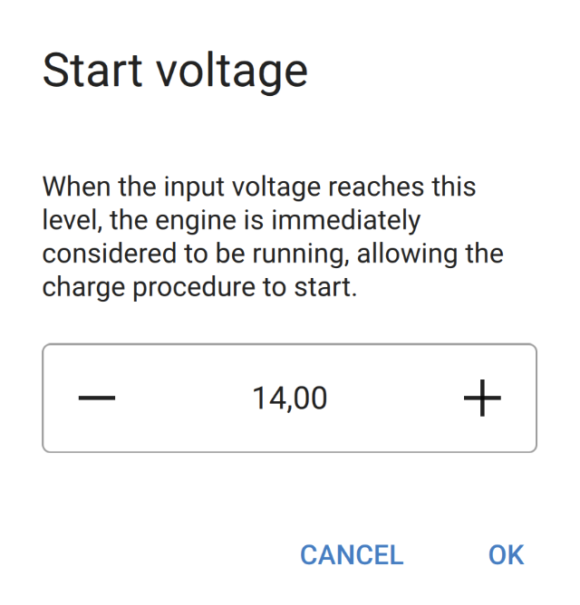
Start voltage (Vstart): At this level, charging starts immediately. |
| |
Delayed start voltage (Vstart(delay)): Smart alternators can generate a lower voltage when the engine is running, therefore a lower start level is necessary for these systems. To ensure that the starter battery is recharged after starting the engine, charging of the auxiliary battery is delayed during this condition. The energy used during starting must be replenished to ensure that the starter battery remains properly charged. |
| |
Delayed start voltage delay (tstart delay): Recharge time for the starter battery during start voltage mode. Example: If the starter draws 150 A for 5 seconds to start the engine, approx. ~0,2 Ah is drawn from the starter battery. If, during engine idling, the alternator can only generate 20 A, it takes 150 A/20 A x 5 s = 37,5 s to recharge the starter battery. |
| |
Shutdown voltage (Vshutdown): This level corresponds with the engine being off. This keeps the starter battery fully charged and provides a hysteresis with respect to the start level. The hysteresis must be large enough to prevent VIN to drop to Vshutdown which would result in charge current reduction. Action will be taken after tshutdown runs out (1 minute); this allows charging during temporary low-voltage conditions. Setting range for start and stop voltages: 9 to 35 V |
|
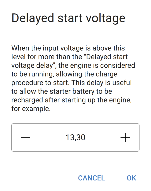
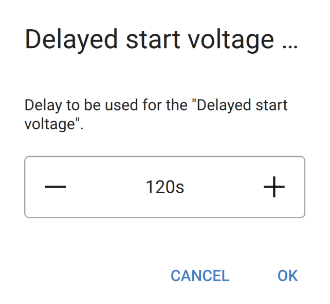
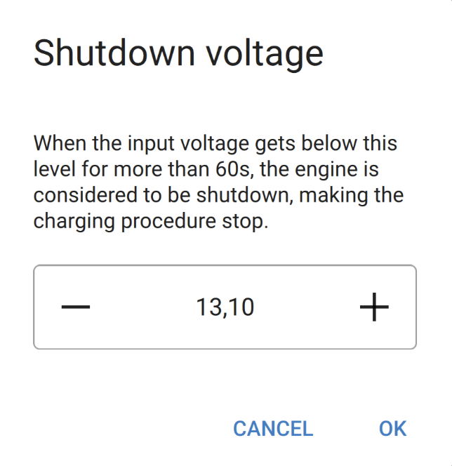
The default values depend on the selected alternator type. Values are given as 12V system / 24V system.
Setting | Smart alternator | Regular alternator |
|---|---|---|
Start voltage (Vstart) | 14 V / 28 V | 14 V / 28 V |
Delayed start voltage (Vstart(delay)) | 13,3 V / 26,6 V | 13,8 V / 27,6 V |
Delayed start voltage delay (tstart delay) | 120 s | 120 s |
Shutdown voltage (Vshutdown) | 13,1 V / 26,2 V | 13,5 V / 27 V |
When the charger is off because the engine shutdown detection has determined that the engine is not running, or because the input voltage lock-out is active, an emergency reverse charge can be started from the VictronConnect App. See Emergency reverse charge.
Input voltage lock-out
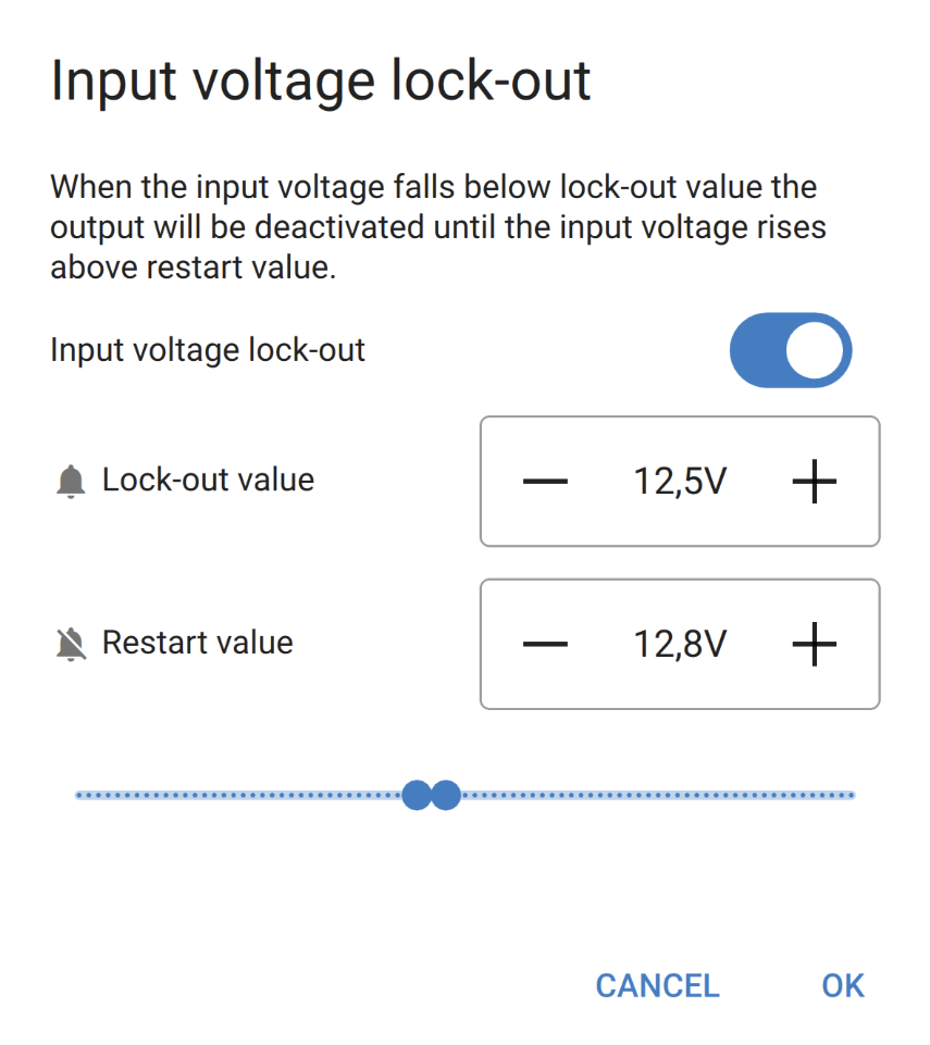
Setup input voltage lock-out: Input voltage lock-out is the minimum level at which charging is allowed, below this level charging stops immediately. Default (in charger mode): lock-out: 12,5 V/25 V; restart: 12,8 V/25,6 V. Default (in power supply mode): lock-out: 10,5 V/21 V; restart: 12 V/24 V. When ‘forced charging’ is enabled, current will be drawn from the starter battery if the engine is not running. Setting the lock-out level very low or deactivating the input voltage lock-out can result in a depleted starter battery. |
| |
To setup input voltage lock-out, two criteria are important:
Example: Calculate the input cable voltage drop:
Cable connections, external fuses, temperature, etc. influence the total cable resistance. |
4.4.7. Product information page
By clicking the  button on the top right of the Settings menu, it is possible to access the product information screen:
Product shows the Orion XS model. | 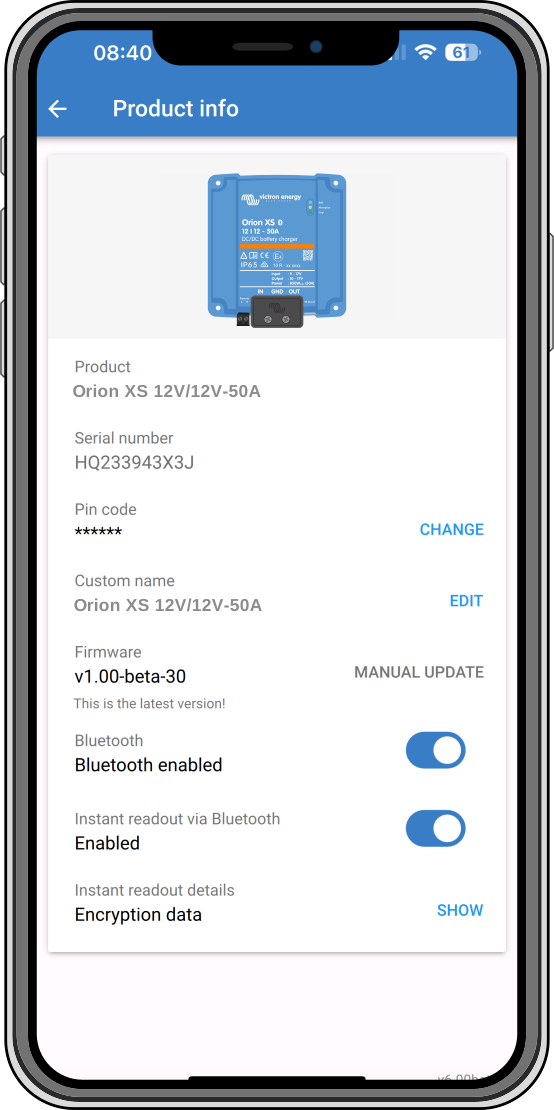 |
Serial number shows the serial number of the unit. | |
Pin code allows the pin code to be changed. This is recommended to be done so settings and information won't be easy to access. | |
Custom name allows you to change a custom product name to your liking. By default, the product name “Orion XS” plus the serial number is displayed. | |
Firmware shows the firmware version currently installed on the device and also allows the charger to be updated if required. | |
Bluetooth: Bluetooth is enabled by default and can be disabled if necessary. To re-enable Bluetooth, please see the "How to disable and re-enable Bluetooth" chapter in the VictronConnect manual. Note that re-enabling Bluetooth requires a VE.Direct to USB interface connection between the Orion XS and a PC, Mac or Android device. iOS devices such as the iPhone and iPad do not support serial USB devices. | |
Instant readout via Bluetooth: Use the slider to disable/enable Instant readout. | |
Instant readout details: Displays the MAC address and encryption key for the unit. |
4.4.8. Monitoring
4.4.9. Charger mode - Status screen
Orion XS [serial number] or a specified custom name confirms the connected device. | 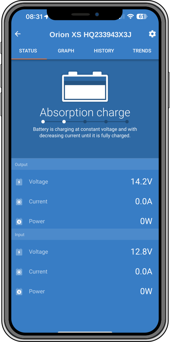 | |
Mode icon: indicates which mode the Orion XS is operating in (in this case Charger Mode). | ||
Charger State:
| ||
Output voltage: Voltage measured at the output terminals of the device. | ||
Output current: Current measured at the output terminals of the device. | ||
Output power: Output power in Watts. | ||
Input voltage: Voltage measured at the input terminals of the device. | ||
Input current: Current measured at the input terminals of the device. | ||
Input power: Input power in Watts. | ||
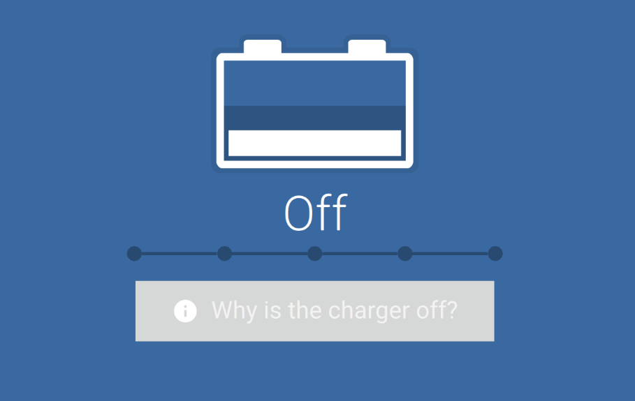
Why is the charger off?: Appears below the battery icon and indicates the reason why the Orion XS is turned off. |
|
4.4.10. Charger mode - Graph screen
Orion XS [serial number] or a specified custom name confirms the connected device. | 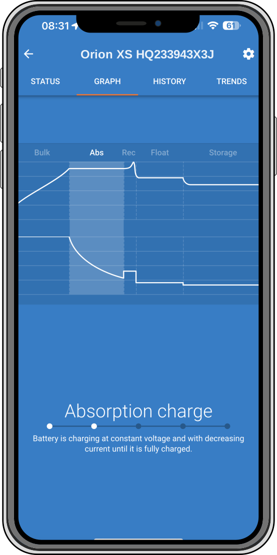 |
Charger State Graph: indicates the current charging state of the Orion XS and provides a short description of the current state. |
4.4.11. History screen
The history page shows a summary of the charge cycles over the previous 40 cycles. Swipe the screen to the right or left to show any of the 40 cycles. Each column represents a cycle. Tapping on one of the bars reveals further information about duration and current for each of the charge states. Other items are: | 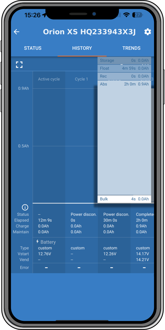 |
Status | |
Elapsed | |
Charge: The accumulated charge current | |
Maintain: The current that keeps the battery fully charged during the float or storage phase. | |
Type: Battery profile used | |
Vstart: The lowest battery voltage at the start of the charge cycle | |
Vend: The lowest battery voltage at the end of the charge cycle | |
Operation time: Accumulated run time of the Orion XS | |
Cycles started: Number of charge cycles started | |
Cycles completed: The number of charge cycles completed (must have reached float or storage voltage stage) | |
Charged Ah:Total amphours charged with the Orion XS |
4.4.12. Trends screen
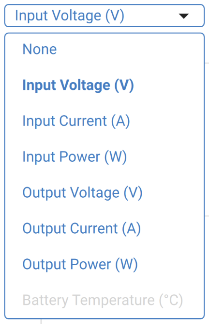
The VictronConnect app allows data to be displayed graphically via the trends screen. The prerequisite is that the VictronConnect app must be open and connected with the Orion XS. The data is not stored permanently. The following parameters can be displayed: | 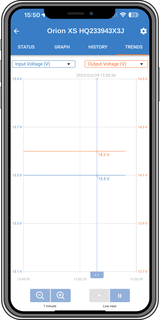
| |
|
4.4.13. Instant readout over BLE
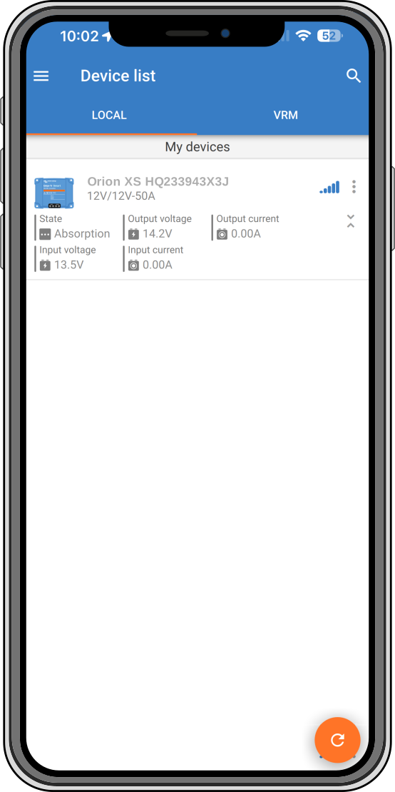
VictronConnect can display key data of the Orion XS (and other compatible smart products) on the Device list page without the need to connect to the product. This includes visual notifications of warnings, alarms, and errors that enable diagnostics at a glance. Please see the Instant Readout chapter in the VictronConnect manual for more information and how to set it up.
The advantage is:
|  |
4.5. Monitoring with a GX device
 |
When the Orion XS is connected to the GX device via its VE.Direct port, it can also be monitored and turned on/off via a GX device's remote console or the VRM portal. The following requirements are necessary for this:
Optionally, an internet connection of the GX device to the VRM portal. This enables remote monitoring from anywhere worldwide and adds VictronConnect Remote (VC-R) functionality. Orion XSVC-R enables remote access even without a direct Bluetooth connection as if standing directly next to the device, with the same functionality. For more details on VC-R, see the VictronConnect manual.
Setup
Connect the Orion XS to the GX device using a VE.Direct cable. It will then automatically appear in the device list of the GX device.
Monitoring
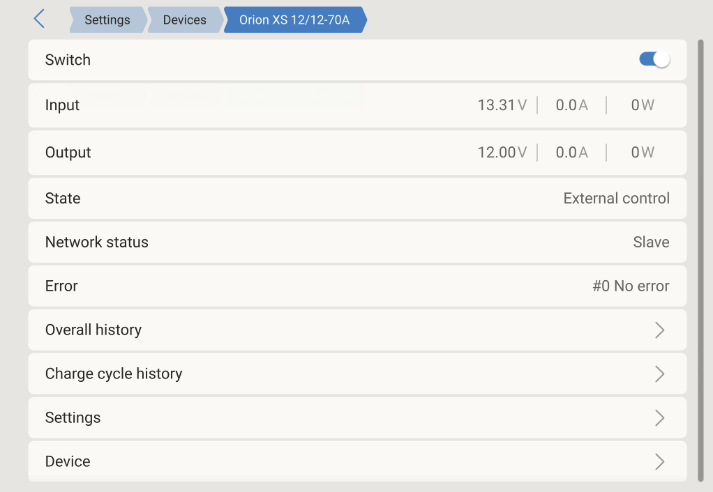
To get to the Orion XS detail page, tap the Orion in the Device list. The detail page offers the following options:
Switch: Turns the Orion XS on and off. Depending on the configuration made in VictronConnect, either charger or power supply mode will be started. | 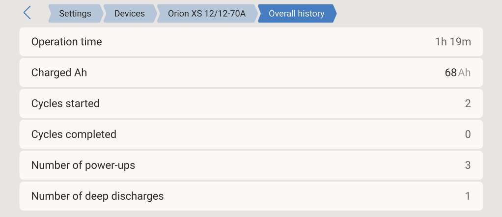 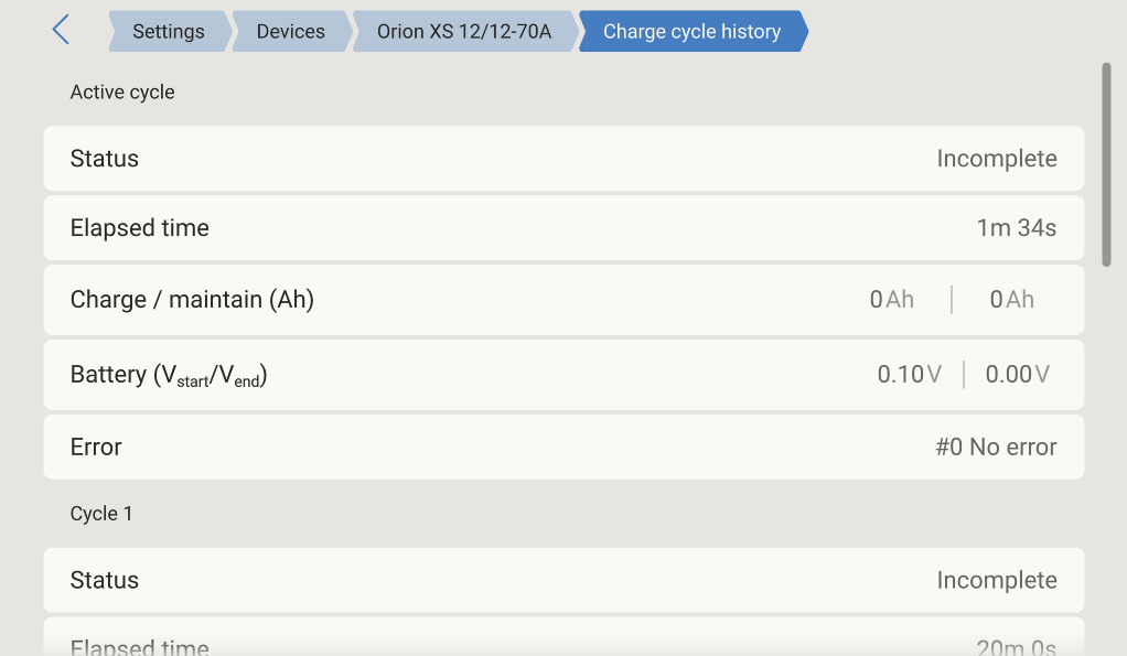 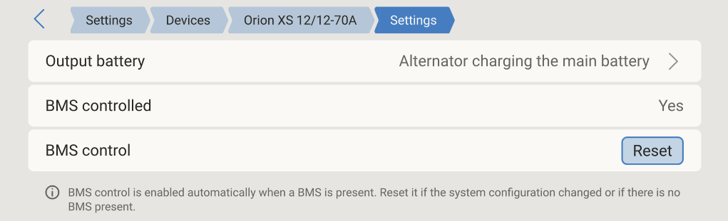  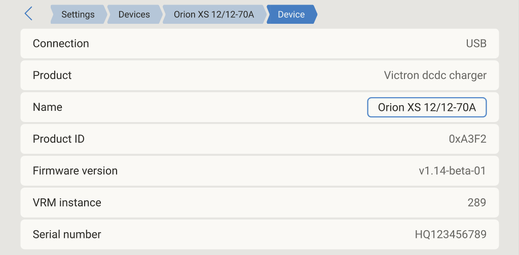 |
Input: Shows the input voltage,current and power as measured at the input terminals. | |
Output: Shows the output voltage, current and power as measured at the output terminals. | |
State: Displays the current status of the charger or power supply mode. Possible states depending on the device mode and settings are: Off (engine not running, or other reason, check the Off reason in VictronConnect), Bulk, Absorption, Float, Storage, Repeated-absorption, Equalize, Auto-equalize, BatterySafe, Ext. control (controlled by a BMS), Power Supply. | |
Network status: This can be either Slave if controlled by DVCC or Standalone device if not controlled by DVCC. | |
Error: If the Orion XS is in an error state, the error code will be displayed here. | |
Overall history: Provides an overview of operation time, number of charge cycles, charged Ah, etc. | |
Charge cycle history: Provides an overview of the last 30 charging cycles. | |
Settings: Provides access to a submenu in which the application type of the Orion XS can be configured.
Device: Provides additional device information and allows to assign a custom device name. |
4.6. Remote sensing with VE.Smart Networking
With VE.Smart Networking, remote battery voltage, temperature and current sensing can be added to your Orion XS when paired with a battery sensor like a BMV, SmartShunt or Smart Battery Sense. The Orion XS will receive the available information from the battery and use that data to optimise its charge parameters.
The sensed battery current is used for the tail current setting, while the battery temperature is used for temperature voltage compensation and protection.
The sensed battery voltage is used to compensate for voltage drop over the battery cables. Compensating for voltage drop creates a mismatch between the voltage measured at the Orion XS connector and the battery terminals:
VOrionXSconnector = Vbattery + Vcompensation
Note
Voltage drop compensation (Vcompensation) saturates at 2V.
Effects when the battery is disconnected
By disconnecting the battery, the physical connection between the charger and the remote sensing device is lost. The charger is not aware that the battery is disconnected and will increase its output voltage to compensate for the voltage difference. In this case, the output voltage will rise until it reaches the saturation level (=2V). E.g. with Vbattery=12.6V, the output voltage (Vconnector) saturates at 14.6V.
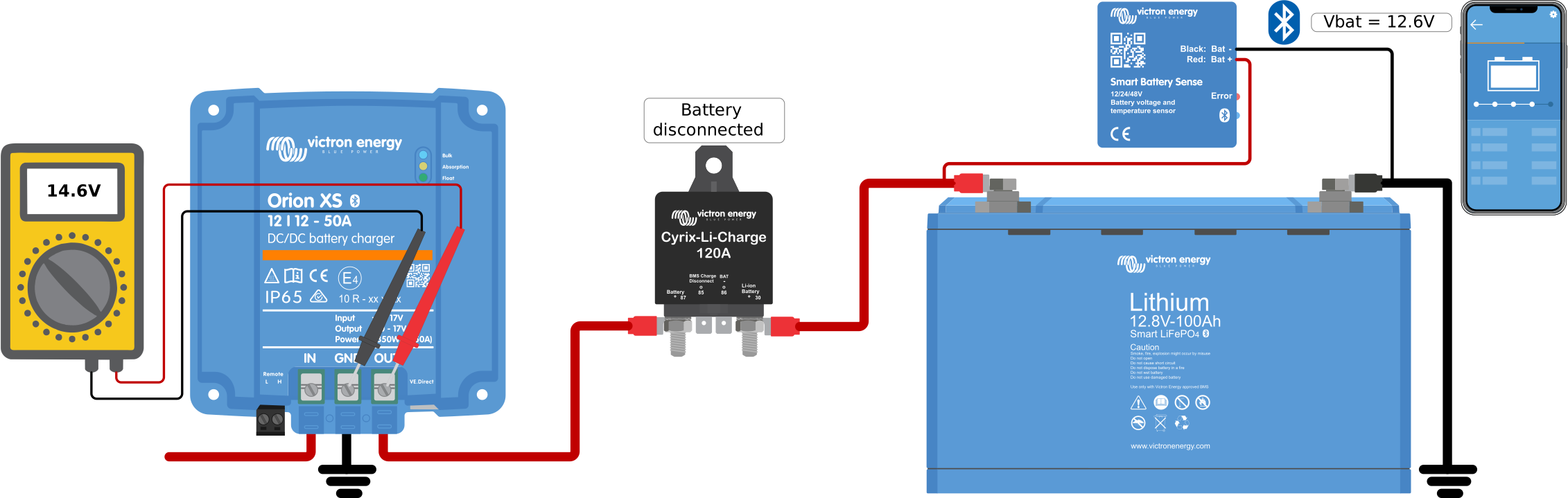
Although it is not a problem that the Orion XS outputs a higher voltage, it can be confusing when analysing the voltage levels in a system and comparing them with the readings of the VictronConnect/GX device. Therefore, when analysing, make sure that all necessary physical connections are made.