3. Installation
3.1. Mounting
Mount vertically on a non-flammable surface, with the power terminals facing downwards.
For optimum performance, a minimum of 10cm space should be kept free around the product for cooling. With limited cooling, e.g. due to insufficient ventilation, the charging current will be reduced sooner than at the specified maximum ambient temperature. With improved airflow (e.g. forced airflow), the performance will greatly improve.
With limited cooling or extreme ambient temperature, the charger can become hot (especially the bottom plate). Due to internal temperature control, the heat sink will never get warmer than 90 °C; this is no problem for the charger. Make sure that the mounting surface can withstand this temperature.
Mount close to the battery but never directly above the battery (to prevent damage from gassing of the battery).
3.2. Cable type recommendations
For correct connection of a cable to the input/output screw terminals, stranded wires with flexible cores can be used according to:
IEC 60228 - Class 2 (stranded), Class 5 (flexible)
UL486A-B - Class B/C (stranded), Class I (flexible)
Cables with twisted cores are very stiff, which means that they are rarely used in practice. The table below provides an overview of how to recognise the different wire classes.
Single wire diameter in the bundle | ||
|---|---|---|
Nominal cross-section | Class 5 (IEC) | Class I (UL) |
10mm2 / 8AWG (8,4mm2) | 0,4mm | 24AWG |
16mm2 / 6AWG (13,3mm2) | 0,4mm | 24AWG |
25mm2 / 4AWG (21,1mm2) | 0,4mm | 24 AWG |
The use of ferrules is not required for cables from the above table. If an even thinner cable is used, a ferrule can help to bundle the loose wires. However, it is up to the installer to make sure that the cable is properly secured. The connecting cable, with or without a ferrule, should be adequately clamped to ensure low contact resistance.
Note: If you prefer using a ferrule, opt for a bootlace ferrule to ensure the strain relief grips the cable insulation as intended. A 16mm² cable with a ferrule will only fit if crimped hexagonally; a square crimp will not fit.
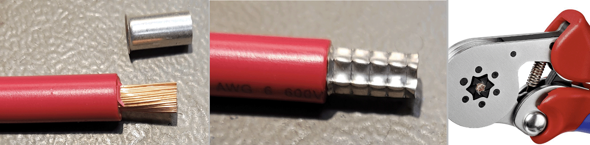
Hexagonally crimped bootlace ferrule
Preparation for correct mounting of fine-strand wires in the screw terminal block
Cut the cable straight with no loose or staggered threads. Using wire cutters will result in a straight cut.
Make sure no fine wires are cut when stripping the insulation.
Open the screw on the screw terminal block completely to prevent fine wires from getting caught behind the screw and bunching up. Pay particular attention to this when using the maximum wire diameter.
Tighten the screw with the correct torque; see Recommended torque and note the wire size and wire class. Never apply less than the recommended torque.
Hold the recommended torque for at least 5 seconds; this will give the screw time to settle to the set torque. This maximises the force on the wire, thereby maintaining a gas-tight contact pattern during heating and cooling cycles over time. Take the time to do it right. This is important. This is a UL486 test requirement and a requirement for all factory and field installations.
3.3. Cable and fuse recommendations
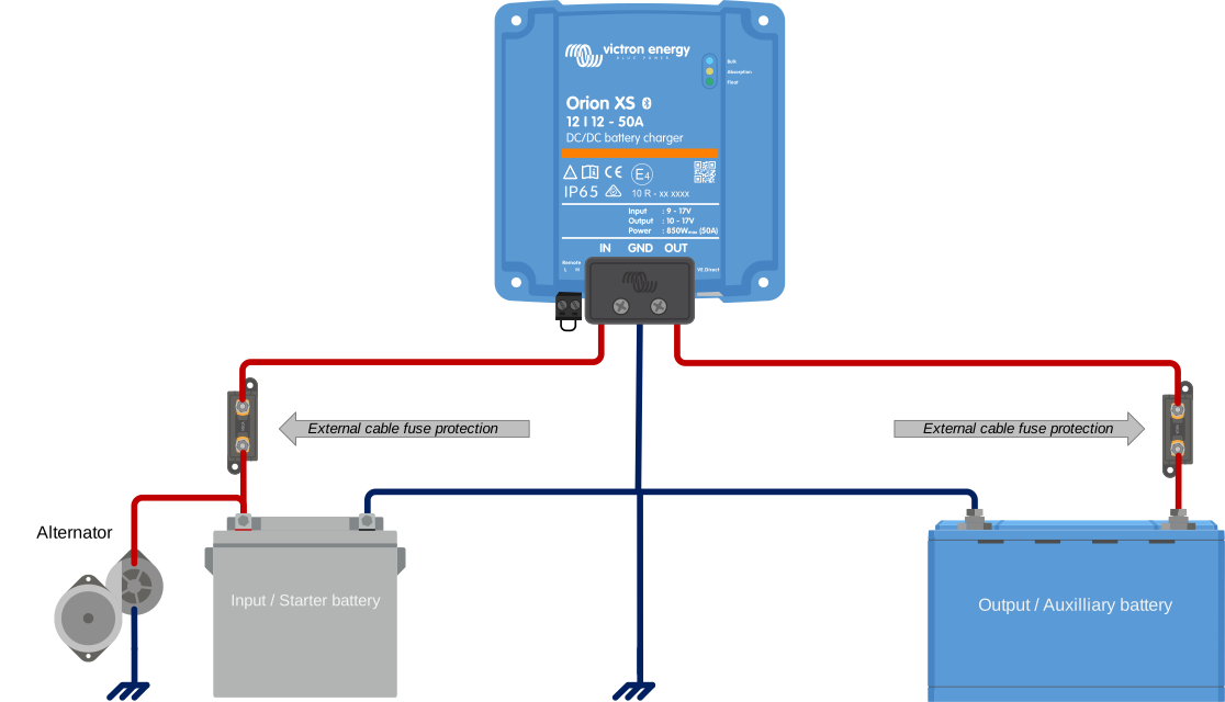
External battery protection fuse | Minimum cable gauge | |
|---|---|---|
60 - 70 A | <5 m | 5 - 10 m |
16 mm2 / 6AWG (13,3mm2) | 4AWG (21,2 mm2) | |
 | ||
3.4. Recommended torque
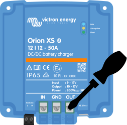
AWG | mm2 | in-lb | Nm |
|---|---|---|---|
4 | 25 | 50 | 5,6 |
6 - 10 | 16 - 6 | 40 | 4,5 |
8 - 12 | 10 - 4 | 25 | 2,8 |
For the cable cover use a torque of <0.7Nm (6 in-lb).
Screwdriver bit information
The screwdriver bit must have a blade thickness of 1,2 mm (0.046”) and minimal taper over at least the first 2 mm (0.08”) of engagement. This reduces the risk of cam-out and ensures correct torque transfer.
Common 6,3 mm (0.25”) screwdriver bits with a thinner 1 mm (0.04”) blade are not recommended.
3.5. GND connection
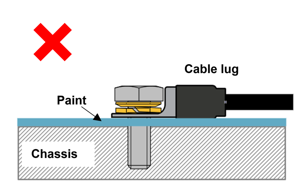
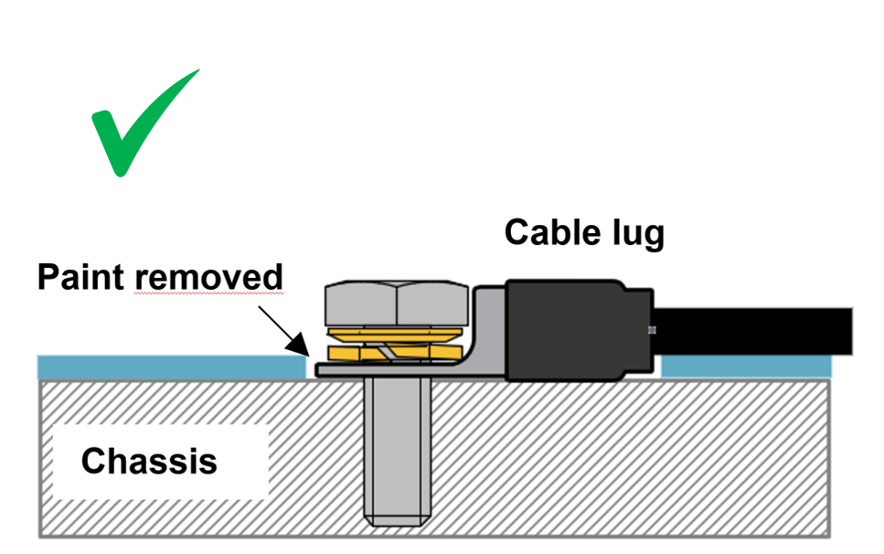
In many cases, the GND connection is connected to the chassis via a cable lug. For a low-impedance connection, the cable lug must have direct contact with the metal of the chassis, the contact surface must therefore be free of paint, see below images.
Important
Make sure the GND connection on the vehicle's chassis has a low impedance.
 |  |
3.6. Strain Relief
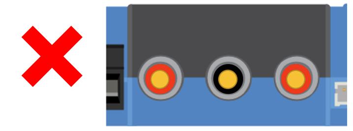
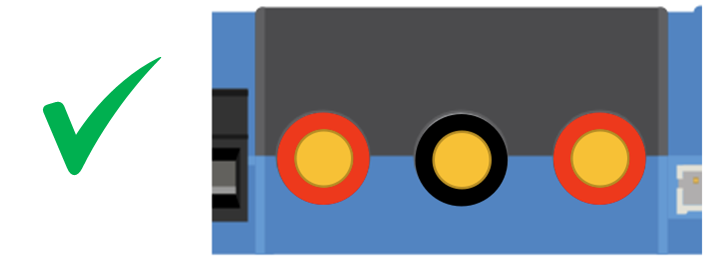
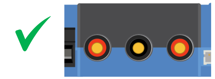
The connector type in this charger is sensitive to constant mechanical stress. Prolonged loading (pulling, pushing or twisting) of the connector should be avoided. For this reason, the charger is equipped with a strain relief in the cable cover. It is very important that the strain relief is applied correctly. The weight of the wire or other forces hanging from the connectors should be close to zero.
Caution
Insufficient strain relief can lead to connector damage in the long term.
The strain relief in the cable cover is designed so that wiring with an outer diameter >9mm is sufficiently clamped. With thinner wiring, the diameter must be increased to >9mm; this can be done simply by applying shrink tubing.
Wire diameter too small - not clamped | Wire diameter >9mm - properly clamped | Wire diameter increased >9mm - properly clamped |
|---|---|---|
 |  |  |
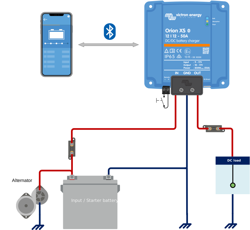
3.7. Connection setup for DC-DC power supply mode
Disconnect the remote on/off (remove the wire bridge or remove the entire remote on/off terminal block).
Connect the input power cables.
Open the VictronConnect app to set up the product (always adjust the output voltage before connecting a load or battery to the output).
For details, see Power supply mode settings.
Connect the load.
Reconnect the remote on/off to activate the product. The product is now ready for use.
Typical connection setting as DC-DC battery charger
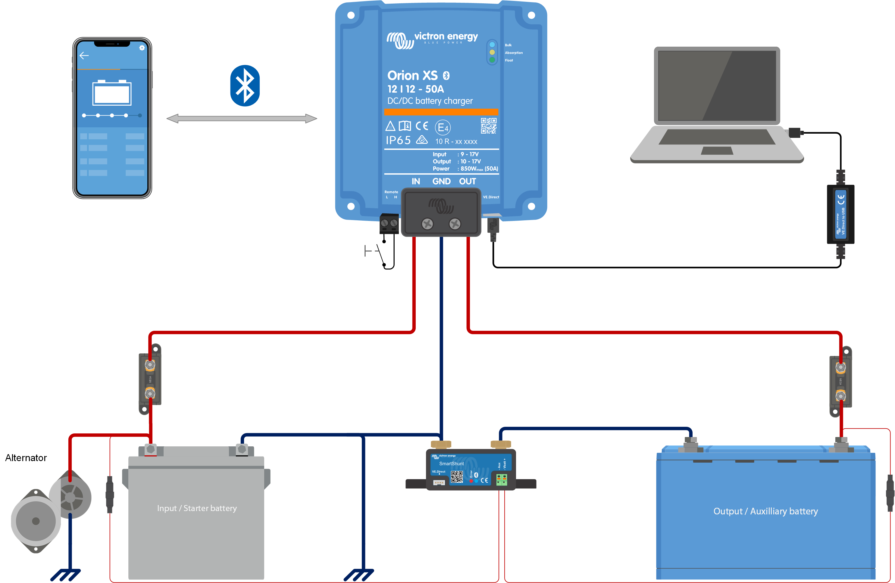
3.8. Connection setup for charger mode
Disconnect the remote on/off (remove the wire bridge or remove the entire remote on/off terminal block).
Connect the input power cables.
Open the VictronConnect App to set up the product (always set up the correct charging algorithm before connecting a battery to the output).
For details, see Charger mode settings.
Connect the battery to be charged.
Reconnect the remote on/off to activate the product. The product is now ready for use.
Typical connection setting as DC-DC battery charger:
 |
3.9. Connection setup for remote on/off
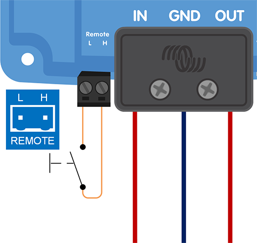
The remote on/off function switches the Orion XS on and off via the two-pole remote connector (L- and H-pin), without the need to interrupt the heavy DC cabling. It gives the versatility to choose from four wiring options, depending on what is available in the installation: a simple switch, a switched positive or negative signal already present in the system, or a BMS charge control contact.
The Orion XS is delivered with a wire loop (bridge) installed between the L- and H-pin. With the wire loop in place, the unit is always on. To switch the unit on and off remotely, remove the wire loop and use one of the options below. |
|
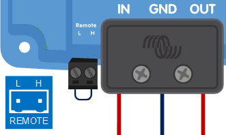
Note
Note the voltage tolerance between L- & H-pin: +/- 70VDC
a) A switch wired between the L-H pins | b) A switch wired between battery pos. and the H-pin |
|---|---|
 ON switch level impedance between L-H pins < 30kΩ | 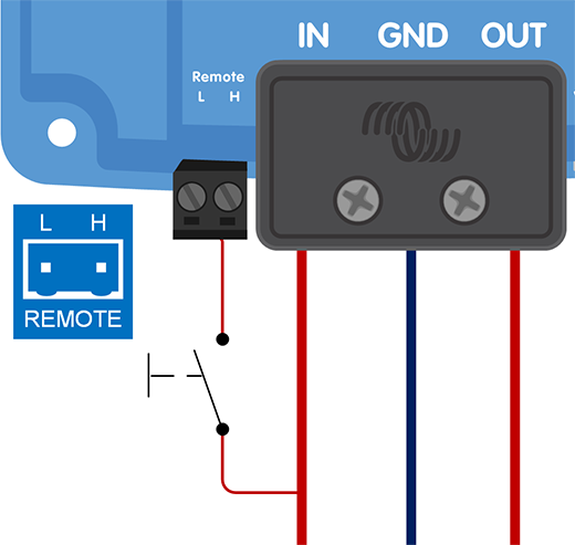 ON switch level > 4V |
c) A switch wired between the L-pin and ground | d) BMS control via the H-pin |
|---|---|
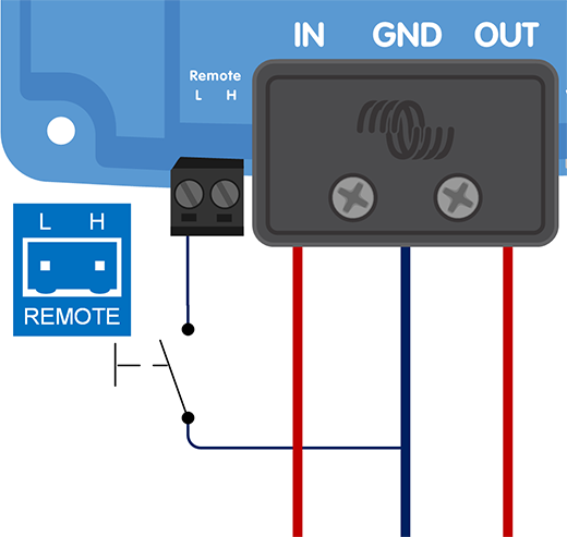 ON switch level < 6V | 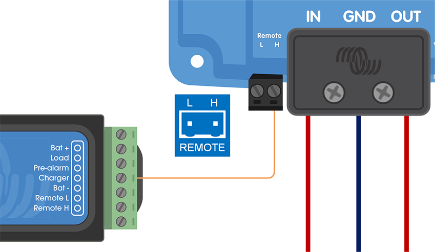 BMS ATC output controls the H-pin |
The Orion XS is on when at least one of the following conditions is met: the L- and H-pin are interconnected, either by the wire loop or by a switch (option a), the H-pin is pulled high (options b and d) or the L-pin is pulled to battery minus (option c). If none of these conditions is met, the unit is off.
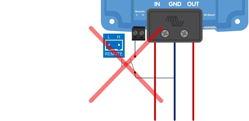
Option a) is the simplest: a plain switch or relay contact, with no connection to the battery poles. Options b) and d) suit installations where a switched positive signal is available, such as a BMS charge control (ATC) contact. Option c) suits installations where a switched negative signal is available, for example a signal switched to the chassis of a vehicle. Option c) cannot be combined with an external engine running signal; see section External engine running signal wiring.
3.10. Wiring examples for BMS-controlled operation
To ensure smooth charging and prevent the risk of overcharging, the chargers must be controlled by the BMS. Depending on the BMS model, this control is either digital, via DVCC, or analogue, via the ATC contact.
DVCC-compatible BMS models
The BMS models listed below can control compatible chargers digitally via DVCC.
VE.Bus BMS V2
VE.Bus BMS NG
Lynx Smart BMS
Lynx Smart BMS NG
Note
DVCC compatibility requires Orion XS firmware v1.03 or later and Venus OS firmware v3.20 or later on the GX device.
Connect a VE.Direct cable between the Orion XS and the GX device and follow the DVCC instructions in the user manual of the BMS. There is no need to wire the BMS ATC contact to the remote H-pin. | 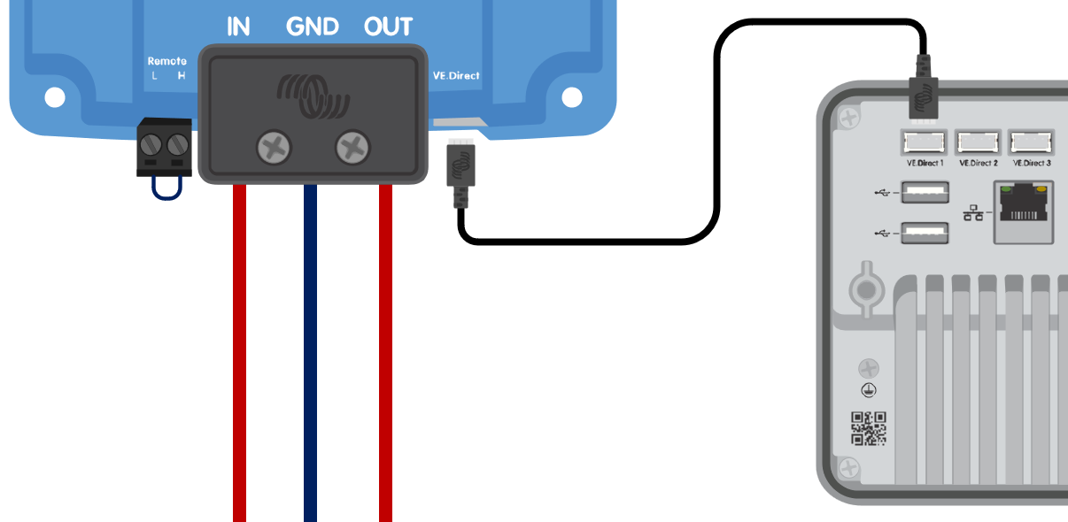 The Orion XS is controlled by DVCC via a GX device. |
Non-DVCC BMS models
The BMS models listed below control chargers via the ATC contact.
VE.Bus BMS
smallBMS with pre-alarm
smallBMS NG
Smart BMS 12-200
Smart BMS CL 12-200
Wire the BMS ATC contact to the remote H-pin. | The Orion XS is controlled by the BMS ATC contact. |
Notice
Depending on the BMS model, the ATC contact may have a different name, such as "Charge Disconnect", "Charger" or "ATC". Please refer to the relevant section of the BMS manual.
3.11. External engine running signal wiring
An external engine running signal tells the Orion XS that the engine is running. See the Using an external engine running signal section for when such a signal is needed and which sources can provide one.
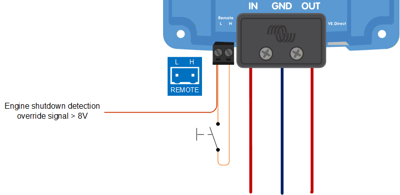
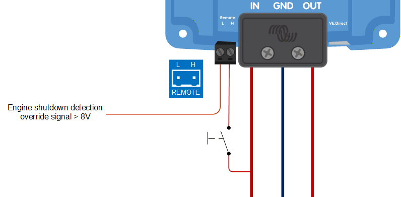
The signal is connected to the L-pin of the remote connector. Applying >8V to the L-pin overrides the engine shutdown detection and activates the charger, even when engine shutdown has been detected.
Notice
This function does not override or replace the remote on/off function. The Orion XS must be switched on via remote on/off for the signal to have effect. This can be the wire loop fitted on delivery, or one of the wiring options shown in section Connection setup for remote on/off.
Wiring examples for the external signal with the various remote on/off options
External signal when remote on/off option a) is used | External signal when remote on/off option b) is used | ||
|---|---|---|---|
A switch between the L-H pins, or the wire loop fitted on delivery |
A switch wired between battery pos. and the H-pin |
External signal when remote on/off option c) is used | External signal when remote on/off option d) is used | |
|---|---|---|
The L-pin is already connected to battery minus. Therefore connecting a positive signal to the same terminal is not allowed. | 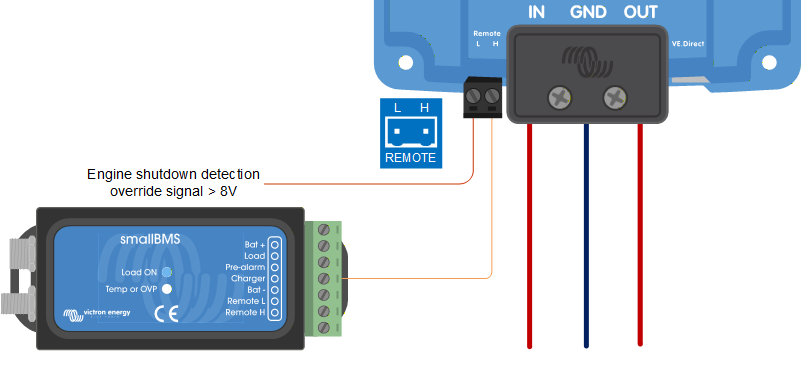 BMS ATC output controls the H-pin |
Wiring a signal that is pulled to ground
Some vehicles provide an engine running signal that is pulled to ground (battery minus) while the engine is running, and is open circuit while the engine is off. This is the opposite of what the L-pin expects, so the signal cannot be connected to the L-pin directly. Use a relay to convert it:
Connect the relay coil between a fused supply from the starter battery positive and the vehicle's engine running terminal.
Connect the normally open relay contact between a fused supply from the starter battery positive and the L-pin.
While the engine runs, the vehicle terminal pulls the relay coil to ground, the relay energises and the contact applies >8V to the L-pin. When the engine stops, the vehicle terminal opens, the relay releases and the signal on the L-pin is no longer present.
Note
Engine running terminals in a vehicle can typically only sink a small current. Use them to drive the relay coil only, never a load. Use a relay with a built-in suppression diode across the coil, or fit one, to protect the vehicle electronics. Consult the vehicle manufacturer's documentation for the availability and ratings of such a signal.
Note
Leave the engine shutdown detection enabled in the VictronConnect App when an external engine running signal is used; see the Using an external engine running signal section.